EP1312884A2 - Elektrolichtbogenofen - Google Patents
Elektrolichtbogenofen Download PDFInfo
- Publication number
- EP1312884A2 EP1312884A2 EP02023263A EP02023263A EP1312884A2 EP 1312884 A2 EP1312884 A2 EP 1312884A2 EP 02023263 A EP02023263 A EP 02023263A EP 02023263 A EP02023263 A EP 02023263A EP 1312884 A2 EP1312884 A2 EP 1312884A2
- Authority
- EP
- European Patent Office
- Prior art keywords
- electric arc
- slide
- arc furnace
- slide plates
- plate
- Prior art date
- Legal status (The legal status is an assumption and is not a legal conclusion. Google has not performed a legal analysis and makes no representation as to the accuracy of the status listed.)
- Withdrawn
Links
Images


Classifications
-
- F—MECHANICAL ENGINEERING; LIGHTING; HEATING; WEAPONS; BLASTING
- F27—FURNACES; KILNS; OVENS; RETORTS
- F27D—DETAILS OR ACCESSORIES OF FURNACES, KILNS, OVENS OR RETORTS, IN SO FAR AS THEY ARE OF KINDS OCCURRING IN MORE THAN ONE KIND OF FURNACE
- F27D3/00—Charging; Discharging; Manipulation of charge
- F27D3/15—Tapping equipment; Equipment for removing or retaining slag
- F27D3/1509—Tapping equipment
-
- F—MECHANICAL ENGINEERING; LIGHTING; HEATING; WEAPONS; BLASTING
- F27—FURNACES; KILNS; OVENS; RETORTS
- F27D—DETAILS OR ACCESSORIES OF FURNACES, KILNS, OVENS OR RETORTS, IN SO FAR AS THEY ARE OF KINDS OCCURRING IN MORE THAN ONE KIND OF FURNACE
- F27D1/00—Casings; Linings; Walls; Roofs
- F27D2001/0046—Means to facilitate repair or replacement or prevent quick wearing
- F27D2001/005—Removable part or structure with replaceable elements
-
- Y—GENERAL TAGGING OF NEW TECHNOLOGICAL DEVELOPMENTS; GENERAL TAGGING OF CROSS-SECTIONAL TECHNOLOGIES SPANNING OVER SEVERAL SECTIONS OF THE IPC; TECHNICAL SUBJECTS COVERED BY FORMER USPC CROSS-REFERENCE ART COLLECTIONS [XRACs] AND DIGESTS
- Y02—TECHNOLOGIES OR APPLICATIONS FOR MITIGATION OR ADAPTATION AGAINST CLIMATE CHANGE
- Y02P—CLIMATE CHANGE MITIGATION TECHNOLOGIES IN THE PRODUCTION OR PROCESSING OF GOODS
- Y02P10/00—Technologies related to metal processing
- Y02P10/20—Recycling
Definitions
- the invention relates to a metallurgical vessel, in particular a non-tiltable Electric arc furnace for melting steel, preferably with one central tapping channel, which is dominated by slide plates with and without opening is guided between an upper and lower guide plate, the Melting steel flows into a ladle when tapping.
- Electric arc furnaces are often equipped with an oriel extension in which there is a tapping channel with a tapping opening. Tapping the molten metal (liquid steel) can only be done by tilting the vessel towards the Oriel attachment, the tapping channel by moving a slide plate is opened. There is sand on the slide plate as a filling compound prevents the metal melt from baking on the slide plate. The sand will filled from above into the tapping channel as long as the furnace has not yet tilted.
- DE 198 26 085 A1 achieves this of a slag-free tapping a stopper for the tap opening with a Provide a plug casing in which there is heat-resistant, flowable material. After use, the tap opening is pushed through from the outside of the vessel closed the stopper. The material of the stopper casing changes its consistency and / or its shape so that the flowable material seals in the tap opening spreads. While this solution is of high quality, it could not enforce in practice.
- EP 0 624 769 A1 Another method of closing the bottom of a metallurgical Vessel is disclosed in EP 0 624 769 A1. It consists in the introduction a flowable material mixed with a binder into the bottom tapping opening. The combustion residue of the binder and the flowable Material clogs the tap hole and protects a conventional slide plate before contact with the melt.
- DE 32 30 646 C1 also describes a method and an apparatus for Closing the tap hole of a fixed, non-tilting electric arc furnace known, in which a previously introduced under pressure from the outside Darning mass of a pourable, refractory material to displace the Melt leads up and so a conventional slide plate before touching preserved with the melt. This will cause the melt to bake on the Slider plate prevented and wear of the same reduced.
- a disadvantage is the use of protective materials for the slide plates Contamination of the melt by the protective masses and the large amount of operation at racking.
- EP 0 942 796 B1 describes a method and an apparatus for discontinuous tapping of melts disclosed. This is the racking interrupted by closing a knife gate valve. Then the cools Steel melt in the tapping channel above the knife gate and solidifies a cast plug. This protects the knife gate valve from the melting heat. When tapping again, the cast plug is inductively heated by the The tap channel liquefied again and the knife gate valve opened.
- This solution is expensive and complicated because of the electrical equipment and is used under an electric arc furnace (e.g. to change the tapping channel) hardly suitable.
- Another problem is the baking of molten steel on the cold Avoid slider plates. Leave slide plates with baked steel stop moving and are blocked.
- the invention has for its object in a generic electric arc furnace to simplify the handling of the racking and the described To avoid problems.
- the slide plates are ceramic material, possibly with an incorporated one Graphite or bomitride layer on the melt side, there is no danger baking of the melt on these plates. This also creates the danger clogging of the tapping channel is reduced.
- the guide plates are also made of ceramic. Nevertheless, the thermal stress is high.
- first and second slide plate are provided, the second slide plate having the opening, whose diameter is at least that of the tapping channel in the area of the slide plates equivalent.
- the two slide plates can also come from different Ceramic be made.
- the knife gate valve an introduction to the slide plates and this a first plate magazine, preferably a first round magazine with non-worn slide plates are upstream and that the knife gate valve is a version for Slide plates and this a second plate magazine, preferably a second Round magazine for worn slide plates are connected.
- the first Rundmagazin is a storage for new or unworn slide plates. These reach the area through the introduction between the guide plates of the tapping channel. From there the more or less worn out Slider plates on the execution in the second round magazine, which has a memory for the worn slide plates. The worn slide plates can be used again after coating with bomitrid.
- the two round magazines, the insertion and execution and the two guide plates are part of the quick-change device.
- linear stacking magazines are also conceivable, which save space and are particularly easy to reload and enable high storage capacity.
- the round magazines have a horizontal axis and preferably 24 arranged parallel to this and tangential to the circumference of the round magazines Have storage spaces for the slide plates.
- the relatively large number the storage locations enable a correspondingly long operating time for the quick-change device, until a change or refilling and emptying of the magazines is required.
- a prerequisite for trouble-free transport of the slide plates is that these, which are between the guide plates and in the insertion and execution as well located in the round magazines are arranged in alignment.
- An advantageous embodiment of the invention is that on the tapping channel far sides of the round magazines linear drives are provided, which with the Align the slide plates and move the slide plates freely for axial play serve between the round magazines. In this way, the slide plates can be easily pushed through the quick-change device.
- the linear drives can be electrical, hydraulic or pneumatic be trained.
- each of the round magazines has a rotary drive, and that the rotary drives run synchronously. But it is also conceivable that a common Drive with rotary connection provided between the two round magazines is.
- tapping channel over the entire length in the direction of flow Melt is flared. This creates the risk of the tapping channel becoming blocked reduced by baked-on melt residues and a loosening of a possibly existing cast plug simplified. Baking on the tap wall is complicated by the fact that an upper part of the tapping channel, which is located above the slide plates, made of ceramic, which is a renewable Has boron nitride coating.
- the steel column in the vessel is usually the Push the stopper down. If that doesn't work, it will be an effective one Measure for releasing and removing a blockage in the tapping channel proposed; it consists in that in the axial direction of the tapping channel Bumper is arranged from its parking position in the vessel cover of the Electric arc furnace is movable from the tapping channel. A light push this ram causes the steel plug to fall down and the tapping channel free is. The prerequisite for this is that the knife gate valve be opened beforehand could.
- the slide plates are made of a ceramic material with high thermal conductivity, preferably Aluminum nitride or silicon carbide exist.
- the high thermal conductivity leads to equalize the temperature of the slide plates and thus reduce their Delay. This avoids cracks and the sealability of the same receive. Because the slide plates have a boron nitride coating largely prevents caking of melt residues.
- the linear drives which are preferably a frequency of 1 Hz and an amplitude of 1.5 to 3 mm. In this way, sticking of the slide plates under the solidified steel plugs can be prevented.
- tapping channel components Another way to extend the life of the tapping channel components is that a double knife gate valve is used.
- flowable filling material preferably sand
- the slide plate can the tapping channel after a short time release and is therefore only in full contact with the melt for a short time. It is less thermally stressed, while the second slide plate is protected by the sand.
- the sheet steel insert is preferably made of consists of the material of the melt, it will not melt due to its melting contaminated.
- Figure 1 shows the bottom of a tilting electric arc furnace 1 for Melting of steel, a base plate 6 and a lining covering this 4 made of fireproof, insulating material. This is from one Penetration channel 5 penetrated, which is composed of an upper part 2 and a lower part 3 which are both made of ceramics.
- the knife gate valve 7 Between the upper and lower part 2, 3 there is a knife gate valve 7, which for Open and close the tapping channel 5 and thus to control the tapping the molten steel 57 is used.
- the knife gate valve 7 has linearly displaceable Slider plates 8, 8 'and a fixed upper and lower guide plate 9, 10th on, which serve to guide and seal the slide plates 8, 8 '.
- the slide plates 8, 8 ' are the high temperature and pressure of the molten steel 57 exposed. As a result, they are subject to a relatively high level Wear and must therefore be replaced relatively often. It serves a quick-change device 11 in the direction of movement of the slide plates 8, 8 'seen before and after the knife gate valve 7 is arranged.
- To the quick-change device 11 include a first and second round magazine 12, 13 and an introduction 14 and an embodiment 15 and a first and second linear drive 16, 17 for the slide plates 8, 8 '.
- the round magazines 12, 13 have one Drum 18 on which is supported on a bearing pin 19 and by a rotary drive 20 are driven synchronously via a gear 21.
- the bearing pin 19 and the rotary drive 20 with a drive pinion 24 are on a bracket 25 attached and this on the base plate 6.
- the drums 18 are down through a cover 27 against the heat of a steel melt filled ladle 28 protected.
- the transport of the slide plates 8, 8 'from the first to the second drum 18 happens by means of the linear drives 16, 17, the plunger 26 in alignment with the slide plates 8, 8 'of the drums 18 of the inlet and outlet 14, 15 and of the knife gate valve 7.
- the second linear drive 17 builds up a force that opposed to the first linear drive 16, but is smaller than its force. In this way, all aligned slide plates 8, 8 'are axial gap during transport freely braced. As a result, the tapping channel 5 remains when passing the slide plate joints tight.
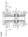
- FIG. 2 shows a vertical section rotated through 90 ° with respect to FIG. 1 a modified tapping channel 5 '.
- Its housing 31 is above a knife gate valve 7 'with an upper ceramic part 29 and below it with a lower ceramic part 30 lined.
- the housing 31 is over clamps 32 connected to the base plate 6.
- the upper one is conical on the outside Ceramic part 29 against the correspondingly designed housing 31 and against a ceramic upper part 2 'and clamped against an upper guide plate 9' and sealed.
- the lower ceramic part 30 is over Flange pieces 33 against the housing 31 and against a lower guide plate 10 'excited.
- the quick-change device 11 is not shown because it is in front of and behind the drawing plane.
- FIG 3 is a simplified horizontal section through the tapping 5 with his Upper part 2 shown. There is a slide plate in the tapping channel position 8 'with the opening 23, whereby the tapping channel 5 is opened. In the Waiting positions before and after the tap channel position are slide plates 8 without opening 23, in the drum positions those with openings 23.
- Figures 4 and 4a show a slide plate 8 with two guides 34, 34 ' work with great leadership. This is necessary to the slide plate 8th to be able to move even if it warps in the company. This is the Case when the same is due to one-sided heating on the hot side 35 through one-sided contact with the melt, one-sided expansion and thereby curves.
- FIGS. 5 and 5a show a slide plate 8 with guides 37 which have little play. From Figure 5 it can be seen that the cold slide plate 8 has a longitudinal curvature 38. By heating the slide plate 8 the hot side 35 expands more than the cold side 36, causing the slide plate 8 becomes flat and, despite the slight play in the guides 37, is displaceable is.
- Another way to prevent thermal distortion is to use it good heat-conducting ceramic, such as aluminum nitride or silicon carbide. As a result, there is an extensive temperature compensation that warps prevented.
- the metallurgical vessel 66 includes a sheet steel casing 41 with supports 40, which are supported on the base plate 6.
- the sheet steel shell 41 is heat-resistant isolating lining 4 provided, at the lowest point of a tap channel 5 "is arranged.
- This has an upper part 2" and a lower part 3 ", which are flared in the direction of flow of the molten steel 57.
- Both parts 2 ", 3” consist of ceramic, at least the upper part 2 "additionally on its inner surface has a Bonitridbelag 42, which makes baking of the melt difficult.
- the quick-change device 11 is not shown in Figure 6 because it is outside the drawing plane is arranged. It is not only used to quickly change the Slider plates 8, 8 'but also the generation of a continuously oscillating Longitudinal movement of the same. This longitudinal movement with an amplitude of 1.5 to 3 mm and a frequency of 1 Hz is provided by the linear drives 16, 17 generated.
- the vessel cover 39 has a different, heat-resistant and insulating covering 4 'on, which is on a steel cover drum 43 on the metallurgical Vessel 66 is supported.
- An electrode adjustment is located on the vessel cover 39 44 for the electrodes 45 with an electrode drive 47 and one Electrode guide 48.
- the electrodes 45 protrude through the other lining 4 ' into the metallurgical vessel 66, where it faces opposing electrodes 49 are positioned.
- the other lining 4 ' is between the electrodes 45 in the axis of the tapping channel 5 "penetrated by a bumper 50, which is made of ceramic and is interchangeable. It has an extension 51 made of steel, which is in an electrode holder 52 is performed. The extension 51 has a drive rack 56, via various bumper drive wheels 54 from a bumper drive pinion 55 can be driven. This bumper drive 53 is about 60 ° in the Drawing level shown pivoted. The extension 51 is also round and is guided in three plain bearings, the lower one is made of ceramic and the two upper ones made of non-ferrous metal. Extension 51 and bumper 50 are threaded connected with each other.
- the bumper 50 is normally retracted in the other liner 4 ' in parking position. It is only when the knife gate valve 7 "is opened through the molten steel 57 into the further tapping channel 5 "and hits the cast plug 69 there. Because of the geometry of the further tapping channel 5 "(conical shape widening downwards) a slight push is enough to get the Loosen cast plug 69 so that it falls down. The loosening of the cast plug 69 is also through the thin renewable boron nitride coating 42 on the inner surface the further upper part 2 "facilitated by the sticking of the Cast plug 69 is avoided.
- FIG 7 shows a horizontal section through the electric arc furnace 1 and Bumper drive 53.
- the electric arc furnace 1 is equipped with three electrodes 45.
- In the middle of the extension 51 is closed with the drive rack 56 recognize, as well as the bumper drive pinion 55 and the numerous bumper drive wheels 54, which bridge the distance to the drive rack 56 and do the necessary translation.
- FIG 8 is a vertical section through a conical tapping channel 5 "" with a pivotable knife gate valve 7 “” shown.
- the conical tapping channel 5 “” points an internally conical upper part 2 "” made of ceramic, which penetrates the lining 4 and is attached to the base plate 6 at the lower end with clips 32.
- the conical upper part 2 "” is when tapping through the ejection of the cast plug 69 and heavily burdened by the subsequent steel melt 57 and must are replaced relatively often.
- a pivotable knife gate valve 7 "" is provided. This points a rectangular frame 70 on a horizontal axis 67 after loosening can be folded down by screws 71.
- the frame 70 is connected to beams 72 which guides 34 for the slide plates 8, 8 'are attached.
- the upper guide plate 9 "” is with an intermediate piece 59 of the tapping channel 5 "", the lower one with a lower part 3 "" of the tapping 5 “” connected in one piece.
- the guide plates 9 "", 10 “” are made of ceramic.
- Figure 9 shows the frame 70 in the folded (solid lines) and in the adjacent State (dashed lines).
- the frame 70 is powered by a hydraulic cylinder 73 pivoted about its horizontal pivot axis 67.
- the hydraulic cylinder 73 is supported on a bearing 75 of a carrier 74 which is on the electric arc furnace 1 "is attached.
- FIG. 10 is a schematic top view of the pivotable frame 70 of Fig. 8, with its horizontal pivot axis 67 and with the Slide plate 8 'together with opening 23 of the plate slide 7 "".
- FIG. 11 shows a longitudinal section through a tapping channel 5 '', with a Upper part 2 "', a lower part 3"', a knife gate valve 7 '' 'and a second knife gate valve 58.
- the knife gate valve 7 "' is an intermediate piece 59 of the tapping channel 5 '' 'arranged.
- the intermediate piece 59 points to its End an upper or lower flange 60, 61, the flanges 60, 61 also serve as lower and upper guide plates for the knife gate valves 7 '' ', 58.
- These also have an upper guide plate 9 '' 'or a second one lower guide plate 62 and a slide plate 8 or a second slide plate 63.
- the slide plate 8 is corresponding with a quick-change device 11 1 connected, the second slide plate 63 with a third linear drive 64.
- a filling opening 65 which with a High pressure source, not shown, is connected to the filling material supply and through which the intermediate piece 59 in a short time with a filling compound, preferably Sand that is fillable.
- the tapping channel 5 '' 'of Figure 11 works as follows:
- both knife gate valves 7 '' ', 58 are opened, so that the molten steel can flow out with the filling material.
- the knife gate valve 7 "' is made of ceramic exists, closed. This makes its slide plate 8 of high thermal Exposed to molten steel 57. At this time if possible to keep short is immediately after closing the knife gate valve 7 "'by the Filling opening 65 blown in sand, which fills the intermediate piece 59. This is the second slide plate 63, which is made of steel, is protected against the melt 57. Therefore, immediately after filling the intermediate piece 59 with sand Knife gate valve 7 '' 'by pushing the gate valve plates 8 without opening 23 opened by the subsequent slide plate 8 'with opening 23.
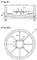
- Figure 12 shows a vertical section through a ladle 28 with an impact protection 76 against the impact of the cast plug 69 when tapping the bottom of the pan 78 made of fireproof material.
- the impact protection 76 consists of a preferably circular, thin-walled sheet steel blank 77, made of four square arranged thin-walled hollow sections 79 is supported from sheet steel.
- the hollow profiles 79 are preferably connected to eight flat profiles 80, which are Support on the pan bottom 78 and the impact protection 76 in the ladle 28 center.
- FIG. 12a shows the ladle 28 with the impact protection 76 in a top view; its steel sheet blank 77, hollow profiles 79 and flat profiles 80 are clear recognizable.
- the impact protection 76 takes the energy of the falling down during tapping Cast plug 69 and thus protects the pan bottom 78 from damage. Subsequently, the one consisting of the material of the molten steel 57 melts Impact protection 76 in the same without contaminating it.
Landscapes
- Engineering & Computer Science (AREA)
- Mechanical Engineering (AREA)
- General Engineering & Computer Science (AREA)
- Furnace Charging Or Discharging (AREA)
- Vertical, Hearth, Or Arc Furnaces (AREA)
Abstract
Description
- Fig. 1
- einen Vertikalschnitt durch einen Abstichkanal eines Elektrolichtbogenofens mit einer Schnellwechselvorrichtung für Schieberplatten,
- Fig. 2
- einen gegenüber Fig. 1 um 90° gedrehten Vertikalschnitt eines modifizierten anderen Abstichkanals,
- Fig. 3
- eine vereinfachte Draufsicht auf die Schnellwechselvorrichtung von Fig. 1,
- Fig. 4
- einen Vertikalschnitt durch eine in einer Führung gehaltene Schieberplatte in kaltem Zustand,
- Fig. 4a
- die Schieberplatte von Fig. 4, jedoch in heißem Zustand,
- Fig. 5
- einen Vertikalschnitt durch eine in einer anderen Führung gehaltene andere Schieberplatte in kaltem Zustand,
- Fig. 5a
- die andere Schieberplatte von Fig. 5 jedoch in heißem Zustand,
- Fig. 6
- einen Vertikalschnitt durch einen Elektrolichtbogenofen mit einer Stoßstange für den Abstichkanal und einen Stoßstangenantrieb,
- Fig. 7
- einen Horizontalschnitt durch den Elektrolichtbogenofen von Fig. 6,
- Fig. 8
- einen Vertikalschnitt durch einen Abstichkanal mit einem schwenkbaren Rahmen und einem darin eingebauten Plattenschieber,
- Fig. 9
- der Rahmen von Fig. 8 in geschwenktem Zustand,
- Fig. 10
- eine Draufsicht auf den schwenkbaren Rahmen von Fig. 8,
- Fig. 11
- einen Längsschnitt durch einen alternativen Abstichkanal mit zwei im Abstand übereinander liegenden Plattenschiebem,
- Fig. 12
- einen Vertikalschnitt durch eine Gießpfanne mit einem Aufprallschutz des Pfannenbodens,
- Fig. 12a
- eine Draufsicht auf die Gießpfanne von Fig. 12 mit dem Aufprallschutz.
- 1
- Elektrolichtbogenofen
- 1'
- Elektrolichtbogenofen
- 1"
- Elektrolichtbogenofen
- 2
- Oberteil
- 2'
- Oberteil
- 2"
- Oberteil
- 2"'
- Oberteil
- 2""
- Oberteil
- 3
- Unterteil
- 3'
- Unterteil
- 3"
- Unterteil
- 3'''
- Unterteil
- 3""
- Unterteil
- 4
- Auskleidung
- 4'
- andere Auskleidung
- 5
- Abstichkanal
- 5'
- Abstichkanal
- 5"
- Abstichkanal
- 5"'
- Abstichkanal
- 5""
- Abstichkanal
- 6
- Grundplatte
- 7
- Plattenschieber
- 7'
- Plattenschieber
- 7"
- Plattenschieber
- 7"'
- Plattenschieber
- 7""
- Plattenschieber
- 8
- Schieberplatte ohne Öffnung
- 8'
- Schieberplatte mit Öffnung
- 9
- obere Führungsplatte
- 9'
- obere Führungsplatte
- 9"
- obere Führungsplatte
- 9"'
- obere Führungsplatte
- 9""
- obere Führungsplatte
- 10
- untere Führungsplatte
- 10'
- untere Führungsplatte
- 10"
- untere Führungsplatte
- 10"'
- untere Führungsplatte
- 11
- Schnellwechselvorrichtung
- 12
- erstes Rundmagazin
- 13
- zweites Rundmagazin
- 14
- Einführung
- 15
- Ausführung
- 16
- erster Linearantrieb
- 17
- zweiter Linearantrieb
- 18
- Trommel
- 19
- Lagerbolzen
- 20
- Drehantrieb
- 21
- Getriebe
- 22
- Speicherplatz
- 23
- Öffnung
- 24
- Antriebsritzel
- 25
- Konsole
- 26
- Stößel
- 27
- Abdeckung
- 28
- Gießpfanne
- 29
- oberes Keramikteil
- 29'
- oberes Keramikteil
- 30
- unteres Keramikteil
- 30'
- unteres Keramikteil
- 31
- Gehäuse
- 32
- Klammer
- 33
- Flanschstück
- 34
- Führung
- 35
- Heißseite
- 36
- Kaltseite
- 37
- Führung
- 38
- Längswölbung
- 39
- Gefäßabdeckung
- 40
- Stütze
- 41
- Stahlblechhülle
- 42
- Bomitridbelag
- 43
- Abdecktrommel
- 44
- Elektrodenverstellung
- 45
- Elektrode
- 47
- Elektrodenantrieb
- 48
- Elektrodenführung
- 49
- Gegenelektrode
- 50
- Stoßstange
- 51
- Verlängerung
- 52
- Elektrodenhalterung
- 53
- Stoßstangenantrieb
- 54
- Stoßstangenantriebsräder
- 55
- Stoßstangenantriebsritzel
- 56
- Verzahnung auf Verlängerung / Antriebszahnstange
- 57
- Stahlschmelze
- 58
- zweiter Plattenschieber
- 59
- Zwischenstück
- 59'
- anderes Zwischenstück
- 60
- oberer Flansch
- 61
- unterer Flansch
- 62
- zweite untere Führungsplatte
- 63
- zweite Schieberplatte
- 64
- dritter Linearantrieb
- 65
- Füllöffnung
- 66
- metallurgisches Gefäß
- 67
- horizontale Schwenkachse
- 68
- Stahlblecheinsatz
- 69
- Gusspfropfen
- 70
- Rahmen
- 71
- Schraube
- 72
- Balken
- 73
- Hydraulikzylinder
- 74
- Träger
- 75
- Lager
- 76
- Aufprallschutz
- 77
- Stahlblechronde
- 78
- Pfannenboden
- 79
- Hohlprofil
- 80
- Flachprofil
Claims (19)
- Metallurgisches Gefäß, insbesondere ein nicht kippbarer Elektrolichtbogenofen (1) zum Schmelzen von Stahl, mit einem Abstichkanal (5, 5', 5", 5"'), der von Schieberplatten (8, 8') mit und ohne Öffnung (23) beherrscht ist, die zwischen einer oberen und einer unteren Führungsplatte (9, 9', 9", 9"', 10, 10', 10", 10"') eines Plattenschiebers (7, 7', 7", 7''') geführt sind, wobei zumindest die Schieberplatten aus Keramik bestehen, dadurch gekennzeichnet, dass die in intensivem Kontakt zur Schmelze (57) stehenden Schieberplatten (8, 8') mit Hilfe einer Schnellwechselvorrichtung (11) maschinell auswechselbar sind.
- Elektrolichtbogenofen nach Anspruch 1, dadurch gekennzeichnet, dass eine erste und eine zweite Schieberplatte (8, 8') vorgesehen sind, wobei die zweite Schieberplatte (8') die Öffnung (23) aufweist, deren Durchmesser zumindest den des Abstichkanals (5, 5', 5", 5"') im Bereich der Schieberplatten (8, 8') entspricht.
- Elektrolichtbogenofen nach Anspruch 2, dadurch gekennzeichnet, dass dem Plattenschieber (7, 7', 7", 7"') eine Einführung (14) für die Schieberplatten (8, 8') und dieser ein erstes Plattenmagazin, vorzugsweise ein erstes Rundmagazin (12) mit unverschlissenen Schieberplatten (8, 8') vorgeschaltet sind und das dem Plattenschieber (7, 7', 7", 7''') eine Ausführung (15) für die Schieberplatten (8, 8') und dieser ein zweites Plattenmagazin vorzugsweise ein zweites Rundmagazin (13) für verschlissene Schieberplatten (8, 8') nachgeschaltet sind.
- Elektrolichtbogenofen nach Anspruch 3, dadurch gekennzeichnet, dass die Rundmagazine (12, 13) eine horizontale Achse und vorzugsweise 24 parallel zu dieser und tangential zum Umfang der Rundmagazine (12, 13) angeordnete Speicherplätze für die Schieberplatten (8, 8') aufweisen.
- Elektrolichtbogenofen nach Anspruch 4 dadurch gekennzeichnet, dass die Schieberplatten (8, 8'), die sich zwischen den Führungsplatten (9, 9', 9", 9''', 10, 10', 10", 10"') und in der Ein- und Ausführung (14, 15) sowie in den Rundmagazinen (12, 13) befinden, fluchtend angeordnet sind.
- Elektrolichtbogenofen nach Anspruch 5, dadurch gekennzeichnet, dass auf den Abstichkanal fernen Seiten der Rundmagazine (12, 13) Linearantriebe (16, 17) vorgesehen sind, die mit den Schieberplatten (8, 8') fluchten und zum Axialspiel freien Verschieben der Schieberplatten (8, 8') zwischen den Rundmagazinen (12, 13) dienen.
- Elektrolichtbogenofen nach Anspruch 6, dadurch gekennzeichnet, dass die Druckkräfte der Linearantriebe (16, 17) entgegengerichtet sind und dass die Druckkraft des in Transportrichtung wirkenden Linearantriebs größer als die des gegenüberliegenden ist.
- Elektrolichtbogenofen nach Anspruch 7, dadurch gekennzeichnet, dass die Linearantriebe (16, 17) elektrisch, hydraulisch oder pneumatisch ausgebildet sein können.
- Elektrolichtbogenofen nach Anspruch 8, dadurch gekennzeichnet, dass vorzugsweise jedes der Rundmagazine (12, 13) einen Drehantrieb (20,20') aufweist und dass die Drehantriebe (20, 20') synchron laufen.
- Elektrolichtbogenofen nach Anspruch 9, dadurch gekennzeichnet, dass ein Abstichkanal (5") in Fließrichtung der Schmelze auf ganzer Länge konisch erweitert ist.
- Elektrolichtbogenofen nach Anspruch 10, dadurch gekennzeichnet, dass ein Oberteil (2, 2', 2", 2"') des Abstichkanals (5, 5', 5", 5"'), das sich oberhalb der Schieberplatten (8, 8') befindet, aus Keramik besteht und einen erneuerbaren Bornitrid- oder Grafitbelag aufweist.
- Elektrolichtbogenofen nach Anspruch 11, dadurch gekennzeichnet, dass in der Achsrichtung des weiteren Abstichkanals (5") eine Stoßstange (50) angeordnet ist, die von ihrer Parkposition in der Gefäßabdeckung (39) des Elektrolichtbogenofens (1) aus in den Abstichkanal (5") bewegbar ist.
- Elektrolichtbogenofen nach Anspruch 12, dadurch gekennzeichnet, dass die Schieberplatten (8, 8') aus einem Keramikwerkstoff hoher Wärmeleitfähigkeit, vorzugsweise Aluminiumnitrid oder Siliciumcarbid bestehen.
- Elektrolichtbogenofen nach Anspruch 13, dadurch gekennzeichnet, dass die Schieberplatten (8, 8') einen Bonitrid- oder Grafitbelag aufweisen.
- Elektrolichtbogenofen nach Anspruch 14, dadurch gekennzeichnet, dass die Schieberplatten (8, 8') im kalten Zustand eine nach unten durchhängende Längswölbung (38) aufweisen.
- Elektrolichtbogenofen nach Anspruch 15, dadurch gekennzeichnet, dass die Schieberplatten (8, 8') durch die Linearantriebe (16, 17) in Längsschwingungen versetzbar sind, die vorzugsweise eine Frequenz von 1Hz und eine Amplitude von 1,5 bis 3 mm aufweisen.
- Elektrolichtbogen nach Anspruch 16, dadurch gekennzeichnet, dass ein Plattenschieber (7"") um eine horizontale Achse (67) nach unten wegklappbar ausgebildet ist.
- Elektrolichtbogenofen nach Anspruch 17, dadurch gekennzeichnet, dass unterhalb eines Plattenschiebers (7''') mit den Schieberplatten (8, 8') ein zweiter Plattenschieber (58) mit einer zweiten Schieberplatte (63) mit Abstand angeordnet ist, und das ein Zwischenstück (59) eines Abstichkanals (5''') zwischen den Schieberplatten (8, 8', 63) mit fließfähigem Füllmaterial, vorzugsweise Sand, füllbar ist, der die zweite Schieberplatte (63) nach dem Öffnen des Plattenschiebers (7''') vor einem Kontakt mit der Stahlschmelze (57) schützt.
- Elektrolichtbogenofen nach Anspruch 18, dadurch gekennzeichnet, dass auf dem Boden einer Gießpfanne (28) ein verlorener Stahlblecheinsatz (68) angeordnet ist, der beim Abstich den oberhalb des Plattenschiebers (7") befindlichen Gusspfropfen (69) auffängt und der in der nachfolgenden Stahlschmelze (57) einschmilzt.
Applications Claiming Priority (2)
| Application Number | Priority Date | Filing Date | Title |
|---|---|---|---|
| DE10156355A DE10156355A1 (de) | 2001-11-16 | 2001-11-16 | Elektrolichtbogenofen |
| DE10156355 | 2001-11-16 |
Publications (2)
| Publication Number | Publication Date |
|---|---|
| EP1312884A2 true EP1312884A2 (de) | 2003-05-21 |
| EP1312884A3 EP1312884A3 (de) | 2003-10-01 |
Family
ID=7706003
Family Applications (1)
| Application Number | Title | Priority Date | Filing Date |
|---|---|---|---|
| EP02023263A Withdrawn EP1312884A3 (de) | 2001-11-16 | 2002-10-17 | Elektrolichtbogenofen |
Country Status (2)
| Country | Link |
|---|---|
| EP (1) | EP1312884A3 (de) |
| DE (1) | DE10156355A1 (de) |
Cited By (1)
| Publication number | Priority date | Publication date | Assignee | Title |
|---|---|---|---|---|
| US20220062980A1 (en) * | 2020-08-28 | 2022-03-03 | Oskar Frech Gmbh + Co. Kg | Foundry Component Having an Anticorrosion Layer Structure |
Family Cites Families (4)
| Publication number | Priority date | Publication date | Assignee | Title |
|---|---|---|---|---|
| US3352465A (en) * | 1965-05-06 | 1967-11-14 | United States Steel Corp | Refractory closure member for bottom pour vessels |
| US4896801A (en) * | 1967-07-11 | 1990-01-30 | Flo-Con Systems, Inc. | Method for controlling the discharge channel of a casting container (tundish) for metallic meltings, and a device for carrying out the method |
| DE19641169C1 (de) * | 1996-10-08 | 1998-05-28 | Didier Werke Ag | Verfahren und Vorrichtung zum disontinuierlichen Abstechen von Schmelzen |
| JP3727467B2 (ja) * | 1998-04-28 | 2005-12-14 | 株式会社神戸製鋼所 | 溶融金属容器の残鋼残滓排出装置 |
-
2001
- 2001-11-16 DE DE10156355A patent/DE10156355A1/de not_active Withdrawn
-
2002
- 2002-10-17 EP EP02023263A patent/EP1312884A3/de not_active Withdrawn
Cited By (2)
| Publication number | Priority date | Publication date | Assignee | Title |
|---|---|---|---|---|
| US20220062980A1 (en) * | 2020-08-28 | 2022-03-03 | Oskar Frech Gmbh + Co. Kg | Foundry Component Having an Anticorrosion Layer Structure |
| US12502706B2 (en) * | 2020-08-28 | 2025-12-23 | Oskar Frech Gmbh + Co. Kg | Foundry component having an anticorrosion layer structure |
Also Published As
| Publication number | Publication date |
|---|---|
| DE10156355A1 (de) | 2003-05-28 |
| EP1312884A3 (de) | 2003-10-01 |
Similar Documents
| Publication | Publication Date | Title |
|---|---|---|
| DE2627896C2 (de) | Bodenausguß für einen Zwischenbehälter für flüssige Metalle | |
| CH640442A5 (de) | Drehschiebeverschluss fuer metallurgische gefaesse, insbesondere stahlgiesspfannen. | |
| WO2011120673A1 (de) | Schmelzprozess mit durchschiebbarer verblendung | |
| CH617610A5 (en) | Horizontal continuous casting machine for metals | |
| DE69332116T2 (de) | Vorrichtung und Verfahren zum Giessen mit einer zementfreien Verbindung des Schiebeverschlusses mit dem metallurgischen Gefäss | |
| EP0819488A2 (de) | Schiebeverschluss für einen Metallschmelze enthaltenden Behälter | |
| EP1312884A2 (de) | Elektrolichtbogenofen | |
| EP0859678A1 (de) | Verfahren und vorrichtung zum verschliessen einer abstichöffnung | |
| DE7816828U1 (de) | Auslassvorrichtung, insbesondere zum steuern des abflusses des inhalts von behaeltern wie giesspfannen o.dgl. | |
| DE1758681A1 (de) | Vorrichtung und Verfahren zum Vergiessen von Metallen | |
| DE2921742C2 (de) | Elektro-Metallschmelzofen mit im Boden angeordneter Abstichöffnung | |
| EP0589238B1 (de) | Verfahren zur Erneuerung der Heizwände einer Koksofenbatterie | |
| DE102012006582A1 (de) | Schaumisolierung für Behälterwandelemente | |
| DE69111729T2 (de) | Zwischenstück zum Giessen von Gegenständen. | |
| EP0049239B1 (de) | Stranggussvorrichtung | |
| EP0109348B1 (de) | Stopfenstangenanordnung an Abgussöfen und anderen metallurgischen Gefässen | |
| EP1172162A1 (de) | Verfahren und Verschliessen oder Öffnen des Abstichloches eines metallurgischen Gefässes, insbesondere eines Elektrolichtbogenofens und zugehöriger Bodenabstich | |
| EP3851225A1 (de) | Schiebeverschluss für ein metallurgisches gefäss | |
| DE29515315U1 (de) | Feuerfeste Auskleidung für Gefäße, in denen flüssiges Metall erschmolzen, behandelt, warmgehalten und/oder transportiert wird | |
| EP0155255A2 (de) | Spüleinrichtung für ein metallurgisches Gefäss | |
| DE102010006229B3 (de) | Druckofen und Verfahren zum kontinuierlichen Betrieb eines Druckofens | |
| DE102009033934B3 (de) | Abdicht- und Verfüllvorrichtung für einen metallurgischen Ofen, metallurgischer Ofen und Verfahren zum Abstechen eines metallurgischen Ofens | |
| DE19925038C2 (de) | Verfahren und Vorrichtung zum Heißreparieren eines Auslaufes eines insbesondere metallurgischen Gefässes | |
| EP0267366A1 (de) | Feuerfeste Auskleidung, insbesondere für Deckel von Wärmverteilern | |
| DE102004008382A1 (de) | Metallummanteltes Wechselbauteil einer Stahlgießanlage |
Legal Events
| Date | Code | Title | Description |
|---|---|---|---|
| PUAI | Public reference made under article 153(3) epc to a published international application that has entered the european phase |
Free format text: ORIGINAL CODE: 0009012 |
|
| 17P | Request for examination filed |
Effective date: 20021017 |
|
| AK | Designated contracting states |
Designated state(s): AT BE BG CH CY CZ DE DK EE ES FI FR GB GR IE IT LI LU MC NL PT SE SK TR |
|
| AX | Request for extension of the european patent |
Extension state: AL LT LV MK RO SI |
|
| PUAL | Search report despatched |
Free format text: ORIGINAL CODE: 0009013 |
|
| AK | Designated contracting states |
Kind code of ref document: A3 Designated state(s): AT BE BG CH CY CZ DE DK EE ES FI FR GB GR IE IT LI LU MC NL PT SE SK TR |
|
| AX | Request for extension of the european patent |
Extension state: AL LT LV MK RO SI |
|
| AKX | Designation fees paid |
Designated state(s): AT BE BG CH CY CZ DE DK EE ES FI FR GB GR IE IT LI LU MC NL PT SE SK TR |
|
| STAA | Information on the status of an ep patent application or granted ep patent |
Free format text: STATUS: THE APPLICATION IS DEEMED TO BE WITHDRAWN |
|
| 18D | Application deemed to be withdrawn |
Effective date: 20060503 |