EP1312897A2 - Capacitive liquid level sensor for submersed pumps - Google Patents
Capacitive liquid level sensor for submersed pumps Download PDFInfo
- Publication number
- EP1312897A2 EP1312897A2 EP02025510A EP02025510A EP1312897A2 EP 1312897 A2 EP1312897 A2 EP 1312897A2 EP 02025510 A EP02025510 A EP 02025510A EP 02025510 A EP02025510 A EP 02025510A EP 1312897 A2 EP1312897 A2 EP 1312897A2
- Authority
- EP
- European Patent Office
- Prior art keywords
- plates
- liquid
- capacitors
- sensing
- pump
- Prior art date
- Legal status (The legal status is an assumption and is not a legal conclusion. Google has not performed a legal analysis and makes no representation as to the accuracy of the status listed.)
- Granted
Links
- 239000007788 liquid Substances 0.000 title claims abstract description 21
- 239000003990 capacitor Substances 0.000 claims abstract description 22
- 239000002184 metal Substances 0.000 claims 1
- XLYOFNOQVPJJNP-UHFFFAOYSA-N water Substances O XLYOFNOQVPJJNP-UHFFFAOYSA-N 0.000 description 6
- 238000007599 discharging Methods 0.000 description 4
- 230000033001 locomotion Effects 0.000 description 4
- 238000003780 insertion Methods 0.000 description 2
- 230000037431 insertion Effects 0.000 description 2
- 230000001788 irregular Effects 0.000 description 2
- 238000004519 manufacturing process Methods 0.000 description 2
- 239000000463 material Substances 0.000 description 2
- 238000000034 method Methods 0.000 description 2
- 238000009412 basement excavation Methods 0.000 description 1
- 230000007613 environmental effect Effects 0.000 description 1
- 230000000670 limiting effect Effects 0.000 description 1
- 238000005259 measurement Methods 0.000 description 1
- 238000012986 modification Methods 0.000 description 1
- 230000004048 modification Effects 0.000 description 1
- 230000003071 parasitic effect Effects 0.000 description 1
- 230000004224 protection Effects 0.000 description 1
Images


Classifications
-
- G—PHYSICS
- G01—MEASURING; TESTING
- G01F—MEASURING VOLUME, VOLUME FLOW, MASS FLOW OR LIQUID LEVEL; METERING BY VOLUME
- G01F23/00—Indicating or measuring liquid level or level of fluent solid material, e.g. indicating in terms of volume or indicating by means of an alarm
- G01F23/22—Indicating or measuring liquid level or level of fluent solid material, e.g. indicating in terms of volume or indicating by means of an alarm by measuring physical variables, other than linear dimensions, pressure or weight, dependent on the level to be measured, e.g. by difference of heat transfer of steam or water
- G01F23/26—Indicating or measuring liquid level or level of fluent solid material, e.g. indicating in terms of volume or indicating by means of an alarm by measuring physical variables, other than linear dimensions, pressure or weight, dependent on the level to be measured, e.g. by difference of heat transfer of steam or water by measuring variations of capacity or inductance of capacitors or inductors arising from the presence of liquid or fluent solid material in the electric or electromagnetic fields
- G01F23/263—Indicating or measuring liquid level or level of fluent solid material, e.g. indicating in terms of volume or indicating by means of an alarm by measuring physical variables, other than linear dimensions, pressure or weight, dependent on the level to be measured, e.g. by difference of heat transfer of steam or water by measuring variations of capacity or inductance of capacitors or inductors arising from the presence of liquid or fluent solid material in the electric or electromagnetic fields by measuring variations in capacitance of capacitors
- G01F23/268—Indicating or measuring liquid level or level of fluent solid material, e.g. indicating in terms of volume or indicating by means of an alarm by measuring physical variables, other than linear dimensions, pressure or weight, dependent on the level to be measured, e.g. by difference of heat transfer of steam or water by measuring variations of capacity or inductance of capacitors or inductors arising from the presence of liquid or fluent solid material in the electric or electromagnetic fields by measuring variations in capacitance of capacitors mounting arrangements of probes
Definitions
- the present invention relates to an improved device for sensing the level of liquid, particularly for submersed pumps.
- a typical case is the emptying of drainage traps and of water accumulated in excavations in building yards.
- Submersed pumps usually have devices for sensing the level of liquid that allow actuation when the level of the liquid exceeds a maximum value and stop operation if the level of liquid reaches a minimum value.
- the readings of the devices can also be biased as a consequence of a turbulent motion of the liquid.
- a sensing device which is the subject of EPA 01921290.1 in the name of this same Applicant and comprises means for sensing the variation in the electrical and/or magnetic field in relation to the variation of the level of the liquid.
- An embodiment of these sensing means is constituted by two pairs of plates, arranged one above the other, at a pipe in which the liquid is present.
- the plates arranged in an upward region signal that the upper level of the liquid has been reached to a control unit, which switches on the pump.
- the plates arranged in a downward region instead signal when it is timely to stop the pump.
- the method of measuring their charging time is used.
- each capacitor varies considerably when water or air is present as dielectric between the plates (the difference is approximately two orders of magnitude), and the charging time is affected thereby importantly, although the capacitances to be measured are small in absolute terms.
- Figure 1 of the accompanying drawings plots the charging and discharging time of a capacitor.
- the dashed line relates to the capacitor with air as the dielectric, while the solid line relates to water as the dielectric.
- the aim of the present invention is to further improve devices for sensing the level of liquid based on capacitors by eliminating the problems of known types noted above.
- an object of the invention is to provide a device for sensing the level of liquid whose sensing cannot be influenced by any turbulent motions of the liquid or by the presence of foreign objects floating within said liquid.
- Another object is to provide a sensing device that is contained within the dimensions of the pump.
- Another object is to be able to provide pumps that are more compact than current ones.
- Another object is to provide a device that gives advantages in terms of production both to the pump and to the control and actuation circuits.
- an improved device for sensing the level of liquid, particularly for submersed pumps of the type that comprises capacitors with two plates arranged one above the other, characterized in that said plates are arranged in vertical succession at different levels.
- said capacitors are two and are formed by three plates arranged vertically on three different levels, the intermediate plate being shared by the two capacitors and being connected to the ground.
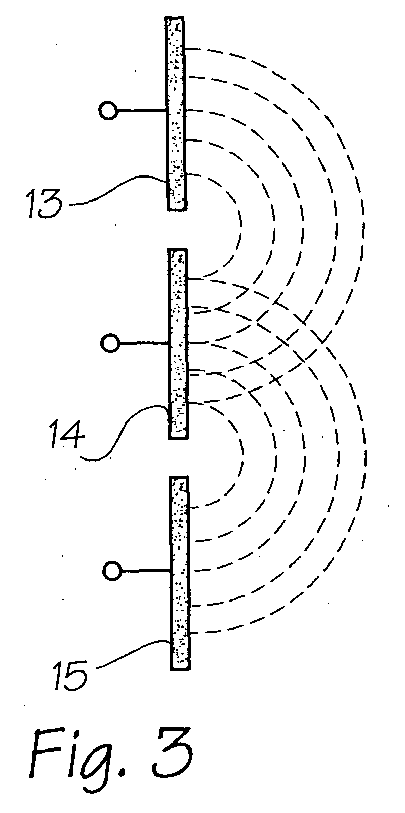
- a device for sensing the level of liquid according to the invention is generally designated by the reference numeral 10.
- the device 10 comprises two capacitors, of the type with two plates, which are arranged one above the other and are designated by the reference numerals 11 and 12 respectively; said capacitors are formed by three flat and co-planar plates arranged in vertical succession at three different levels, and are designated respectively by the reference numerals 13, 14 and 15.
- one of the plates is shared by the two capacitors 11 and 12 and is connected to the ground.
- the plate that is connected to the ground can also be conveniently split.
- At least one third capacitor 16 by arranging alongside the intermediate plate 14 at least one fourth plate 17 in order to sense another variation in capacitance and identify two levels (0 or 1), but in this case in order to check for the presence or absence (capacitance with air as dielectric) of a human finger.
- the fourth plate 17 must be conveniently flat and co-planar to the preceding ones.
- At least one button is provided for controlling the operation of the pump independently of the state of the other two capacitors.
- a typical case can be the particular and manual use of the pump, which currently is possible only by lifting manually the float that controls pump power-on or shutdown.
- the capacitors are connected to a control board, not shown in the figures, which uses logic units or microprocessors to control the motor of the pump, and it is possible to insert protections, such as a block against rotation in the absence of water after a programmable time, in order to protect the hydraulic system, the motor and the mechanical components of said pump.
- a device which does not have external movable appendages and does not require the provision of recesses, irregular shapes, insertion of pipes, to avoid problems due to dirt, floating objects, vortical motions and clogging.
- the three plates can in fact be included and encapsulated in the pump casing or container itself, allowing to provide said pump in a more compact form than currently provided.
- the fact that the plates are on the same plane allows to produce them by using materials and methods that are used for printed circuits, with consequent advantages in terms of production process for providing the assembly constituted by the sensors, the pump, and the connections to the control and actuation circuit.
- the materials used, as well as the dimensions, so long as they are compatible with the contingent use may be any according to requirements.
Landscapes
- Physics & Mathematics (AREA)
- Engineering & Computer Science (AREA)
- Power Engineering (AREA)
- Electromagnetism (AREA)
- Thermal Sciences (AREA)
- Fluid Mechanics (AREA)
- General Physics & Mathematics (AREA)
- Measurement Of Levels Of Liquids Or Fluent Solid Materials (AREA)
- Control Of Positive-Displacement Pumps (AREA)
- Control Of Non-Positive-Displacement Pumps (AREA)
- Control Of Non-Electrical Variables (AREA)
Abstract
Description
- The present invention relates to an improved device for sensing the level of liquid, particularly for submersed pumps.
- As is known, submersed pumps are applied most frequently in evacuating traps or the like, to remove an excessive quantity of liquids gradually accumulated therein.
- A typical case is the emptying of drainage traps and of water accumulated in excavations in building yards.
- Submersed pumps usually have devices for sensing the level of liquid that allow actuation when the level of the liquid exceeds a maximum value and stop operation if the level of liquid reaches a minimum value.
- These known sensing devices are substantially constituted by appendages that protrude outside the dimensions of the pump with end floats which, by being affected by the rise or fall of the level of liquid, activate electrical connections.
- Since they protrude outside the overall dimensions of the pumps, known sensing devices require the traps or spaces from which the liquid is to be evacuated to be larger than such overall dimensions of the pump.
- Moreover, the correct operation of these devices depends also on whether floating objects are present or not within the liquid.
- The presence of a floating foreign object might in fact alter the readings of the device or even damage it.
- Sometimes the readings of the devices can also be biased as a consequence of a turbulent motion of the liquid.
- To solve these drawbacks, a sensing device has been devised which is the subject of EPA 01921290.1 in the name of this same Applicant and comprises means for sensing the variation in the electrical and/or magnetic field in relation to the variation of the level of the liquid.
- An embodiment of these sensing means is constituted by two pairs of plates, arranged one above the other, at a pipe in which the liquid is present.
- The plates arranged in an upward region signal that the upper level of the liquid has been reached to a control unit, which switches on the pump.
- The plates arranged in a downward region instead signal when it is timely to stop the pump.
- To detect the variation in the capacitance of the capacitors that produces the level signal, the method of measuring their charging time is used.
- The capacitance of each capacitor varies considerably when water or air is present as dielectric between the plates (the difference is approximately two orders of magnitude), and the charging time is affected thereby importantly, although the capacitances to be measured are small in absolute terms.
- Figure 1 of the accompanying drawings plots the charging and discharging time of a capacitor.
- The dashed line relates to the capacitor with air as the dielectric, while the solid line relates to water as the dielectric.
- The considerable difference between the charging times t1 and t2 and the discharging times t3 and t4 is evident.
- Electronics currently provides very fast logic units or microcontrollers, and the measurement is performed easily.
- Twin-capacitor devices provide a series of advantages:
- two distinct and clearly identified capacitances are measured in order to check the maximum and minimum levels, because all metallic plates are used and no parasitic capacitors that would introduce uncertainties are used;
- the sensing of the variation in the capacitance according to the charging and/or discharging time does not depend on environmental factors but on a basic principle of physics, the capacitances vary to an important extent, and it is necessary to distinguish only two values per sensor (water or air), digitizing the signal;
- with digital circuitry there is no drift due to analog components.
- Practical execution nonetheless has revealed drawbacks, in particular the need to provide recesses, irregular shapes, insertion of pipes, in order to avoid problems due to dirt, floating bodies, vortical motions and clogging.
- The aim of the present invention is to further improve devices for sensing the level of liquid based on capacitors by eliminating the problems of known types noted above.
- Within this aim, an object of the invention is to provide a device for sensing the level of liquid whose sensing cannot be influenced by any turbulent motions of the liquid or by the presence of foreign objects floating within said liquid.
- Another object is to provide a sensing device that is contained within the dimensions of the pump.
- Another object is to be able to provide pumps that are more compact than current ones.
- Another object is to provide a device that gives advantages in terms of production both to the pump and to the control and actuation circuits.
- This aim and these and other objects that will become better apparent hereinafter are achieved by an improved device for sensing the level of liquid, particularly for submersed pumps, of the type that comprises capacitors with two plates arranged one above the other, characterized in that said plates are arranged in vertical succession at different levels.
- Advantageously, said capacitors are two and are formed by three plates arranged vertically on three different levels, the intermediate plate being shared by the two capacitors and being connected to the ground.
- Further characteristics and advantages will become better apparent from the description of a preferred but not exclusive embodiment of the invention, illustrated only by way of non-limitative example in the accompanying drawings and figures, wherein:
- Figure 1 plots the charging and discharging times of a capacitor in which the dielectric is constituted by air and by water;
- Figure 2 is a schematic side view of a device according to the invention;
- Figure 3 is a schematic front view of a device according to the invention;
- Figure 4 is a schematic front view of a device according to the invention in a different embodiment.
-
- With particular reference to Figures 2 and 3, a device for sensing the level of liquid according to the invention is generally designated by the
reference numeral 10. - The
device 10 comprises two capacitors, of the type with two plates, which are arranged one above the other and are designated by thereference numerals reference numerals - According to the invention, one of the plates, particularly the
intermediate plate 14, is shared by the twocapacitors - The plate that is connected to the ground can also be conveniently split.
- With particular reference to Figure 4, advantageously it is possible to provide at least one
third capacitor 16 by arranging alongside theintermediate plate 14 at least onefourth plate 17 in order to sense another variation in capacitance and identify two levels (0 or 1), but in this case in order to check for the presence or absence (capacitance with air as dielectric) of a human finger. - The
fourth plate 17 must be conveniently flat and co-planar to the preceding ones. - In this case, therefore, at least one button is provided for controlling the operation of the pump independently of the state of the other two capacitors.
- A typical case can be the particular and manual use of the pump, which currently is possible only by lifting manually the float that controls pump power-on or shutdown.
- The capacitors are connected to a control board, not shown in the figures, which uses logic units or microprocessors to control the motor of the pump, and it is possible to insert protections, such as a block against rotation in the absence of water after a programmable time, in order to protect the hydraulic system, the motor and the mechanical components of said pump.
- In practice, it has been found that the present invention has achieved the intended aim and objects.
- In particular, a device has been provided which does not have external movable appendages and does not require the provision of recesses, irregular shapes, insertion of pipes, to avoid problems due to dirt, floating objects, vortical motions and clogging.
- The three plates can in fact be included and encapsulated in the pump casing or container itself, allowing to provide said pump in a more compact form than currently provided.
- Furthermore, the fact that the plates are on the same plane allows to produce them by using materials and methods that are used for printed circuits, with consequent advantages in terms of production process for providing the assembly constituted by the sensors, the pump, and the connections to the control and actuation circuit.
- The present invention is susceptible of numerous modifications and variations, all of which are within the scope of the appended claims.
- All the details may be replaced with other technically equivalent elements.
- In practice, the materials used, as well as the dimensions, so long as they are compatible with the contingent use, may be any according to requirements.
- The disclosures in Italian Patent Application No. PD2001A000269 from which this application claims priority are incorporated herein by reference.
- Where technical features mentioned in any claim are followed by reference signs, those reference signs have been included for the sole purpose of increasing the intelligibility of the claims and accordingly, such reference signs do not have any limiting effect on the interpretation of each element identified by way of example by such reference signs.
Claims (7)
- A device for sensing the level of liquid, particularly for submersed pumps, of the type that comprises capacitors (11,12) with two metal plates (13,14,15), characterized in that said plates (13,14,15) are arranged in vertical succession at respectively different levels.
- The device according to claim 1, characterized in that said plates (13,14,15) are arranged co-planar.
- The device according to claim 1, characterized in that it comprises two capacitors (11,12) formed by three plates (13,14,15) arranged in vertical succession on three different levels, at least one plate (14) being shared by the two capacitors (11,12).
- The device according to claim 3, characterized in that said shared plate is the intermediate plate (14).
- The device according to claim 3, characterized in that said three plates (13,14,15) are flat.
- The device according to one or more of the preceding claims, characterized in that it comprises at least one third capacitor (16), provided by arranging at least one fourth plate (17) laterally to said shared plate (14).
- The device according to claim 6, characterized in that said fourth plate (17) is flat and co-planar to the preceding ones.
Applications Claiming Priority (2)
| Application Number | Priority Date | Filing Date | Title |
|---|---|---|---|
| IT2001PD000269A ITPD20010269A1 (en) | 2001-11-20 | 2001-11-20 | PERFECTED DEVICE FOR THE DETECTION OF LIQUID LEVEL, PARTICULARLY FOR SUBMERSIBLE PUMPS. |
| ITPD20010269 | 2001-11-20 |
Publications (3)
| Publication Number | Publication Date |
|---|---|
| EP1312897A2 true EP1312897A2 (en) | 2003-05-21 |
| EP1312897A3 EP1312897A3 (en) | 2007-03-21 |
| EP1312897B1 EP1312897B1 (en) | 2010-10-06 |
Family
ID=11452483
Family Applications (1)
| Application Number | Title | Priority Date | Filing Date |
|---|---|---|---|
| EP02025510A Expired - Lifetime EP1312897B1 (en) | 2001-11-20 | 2002-11-13 | Capacitive liquid level sensor for submersed pumps |
Country Status (6)
| Country | Link |
|---|---|
| US (1) | US6675647B2 (en) |
| EP (1) | EP1312897B1 (en) |
| AT (1) | ATE483954T1 (en) |
| DE (1) | DE60237871D1 (en) |
| ES (1) | ES2354059T3 (en) |
| IT (1) | ITPD20010269A1 (en) |
Cited By (4)
| Publication number | Priority date | Publication date | Assignee | Title |
|---|---|---|---|---|
| DE102004053626A1 (en) * | 2004-11-01 | 2006-05-04 | Benjamin Hoffmeier | Method of capacitive measurement of degree of fullness and quality over the discharge time of a capacitor acting as a capacitative fullness and quality sensor in a monostable flip switch |
| EP2400275A1 (en) | 2010-06-25 | 2011-12-28 | Siemens Healthcare Diagnostics Products GmbH | Contactless fill level measurement of liquids |
| WO2016059409A3 (en) * | 2014-10-14 | 2016-11-24 | Aspen Pumps Limited | Liquid level detector |
| US12306367B1 (en) * | 2024-04-10 | 2025-05-20 | Aiper Global Pte. Ltd. | Swimming pool cleaning device and cleaning method |
Families Citing this family (5)
| Publication number | Priority date | Publication date | Assignee | Title |
|---|---|---|---|---|
| US8936444B2 (en) * | 2007-12-07 | 2015-01-20 | Pentair Flow Technologies, Llc | Capacitive liquid level sensor |
| WO2012006136A1 (en) | 2010-07-07 | 2012-01-12 | Cervantes Mobile | Compact keyboard and cradle |
| US8869612B2 (en) | 2011-03-08 | 2014-10-28 | Baxter International Inc. | Non-invasive radio frequency liquid level and volume detection system using phase shift |
| US10203238B2 (en) | 2014-03-07 | 2019-02-12 | Barrelogix, Llc | Liquid detection apparatus |
| EP3875765A1 (en) | 2020-03-02 | 2021-09-08 | Husqvarna Ab | Submersible pump with touch sensitive sensors |
Citations (3)
| Publication number | Priority date | Publication date | Assignee | Title |
|---|---|---|---|---|
| EP0377508A1 (en) | 1989-01-06 | 1990-07-11 | Standex International Corporation | Capacitive liquid level sensor |
| US5460007A (en) | 1994-06-28 | 1995-10-24 | Arthur P. Little, Inc. | Ice level sensor for an ice maker |
| WO1999010714A1 (en) | 1997-08-25 | 1999-03-04 | Millennium Sensors Ltd. | A compensated capacitive liquid level sensor |
Family Cites Families (5)
| Publication number | Priority date | Publication date | Assignee | Title |
|---|---|---|---|---|
| US4987776A (en) * | 1988-03-16 | 1991-01-29 | Koon Terry D | Level indicator |
| US5856783A (en) * | 1990-01-02 | 1999-01-05 | Raptor, Inc. | Pump control system |
| US5747689A (en) * | 1996-12-09 | 1998-05-05 | Ford Global Technologies, Inc. | Fluid level sensing system |
| DE19816455A1 (en) * | 1998-04-14 | 1999-10-28 | Mannesmann Vdo Ag | Level sensor for fuel tank |
| WO2000042395A1 (en) * | 1999-01-19 | 2000-07-20 | Rocky Mountain Research, Inc. | Method and apparatus for detection of a fluid level in a container |
-
2001
- 2001-11-20 IT IT2001PD000269A patent/ITPD20010269A1/en unknown
-
2002
- 2002-11-13 ES ES02025510T patent/ES2354059T3/en not_active Expired - Lifetime
- 2002-11-13 AT AT02025510T patent/ATE483954T1/en not_active IP Right Cessation
- 2002-11-13 DE DE60237871T patent/DE60237871D1/en not_active Expired - Lifetime
- 2002-11-13 EP EP02025510A patent/EP1312897B1/en not_active Expired - Lifetime
- 2002-11-13 US US10/292,463 patent/US6675647B2/en not_active Expired - Lifetime
Patent Citations (3)
| Publication number | Priority date | Publication date | Assignee | Title |
|---|---|---|---|---|
| EP0377508A1 (en) | 1989-01-06 | 1990-07-11 | Standex International Corporation | Capacitive liquid level sensor |
| US5460007A (en) | 1994-06-28 | 1995-10-24 | Arthur P. Little, Inc. | Ice level sensor for an ice maker |
| WO1999010714A1 (en) | 1997-08-25 | 1999-03-04 | Millennium Sensors Ltd. | A compensated capacitive liquid level sensor |
Cited By (9)
| Publication number | Priority date | Publication date | Assignee | Title |
|---|---|---|---|---|
| DE102004053626A1 (en) * | 2004-11-01 | 2006-05-04 | Benjamin Hoffmeier | Method of capacitive measurement of degree of fullness and quality over the discharge time of a capacitor acting as a capacitative fullness and quality sensor in a monostable flip switch |
| EP2400275A1 (en) | 2010-06-25 | 2011-12-28 | Siemens Healthcare Diagnostics Products GmbH | Contactless fill level measurement of liquids |
| DE102010025118A1 (en) | 2010-06-25 | 2011-12-29 | Siemens Healthcare Diagnostics Products Gmbh | Non-contact level measurement of liquids |
| US8931340B2 (en) | 2010-06-25 | 2015-01-13 | Siemens Healthcare Diagnostics Products Gmbh | Contactless filling level measurement of liquids |
| WO2016059409A3 (en) * | 2014-10-14 | 2016-11-24 | Aspen Pumps Limited | Liquid level detector |
| CN107003170A (en) * | 2014-10-14 | 2017-08-01 | 艾斯本泵业有限公司 | Liquid level detector |
| GB2531291B (en) * | 2014-10-14 | 2019-12-04 | Aspen Pumps Ltd | Liquid level detector |
| US10760938B2 (en) | 2014-10-14 | 2020-09-01 | Aspen Pumps Limited | Liquid level detector |
| US12306367B1 (en) * | 2024-04-10 | 2025-05-20 | Aiper Global Pte. Ltd. | Swimming pool cleaning device and cleaning method |
Also Published As
| Publication number | Publication date |
|---|---|
| ES2354059T3 (en) | 2011-03-09 |
| US6675647B2 (en) | 2004-01-13 |
| US20030094043A1 (en) | 2003-05-22 |
| ITPD20010269A1 (en) | 2003-05-20 |
| ATE483954T1 (en) | 2010-10-15 |
| EP1312897A3 (en) | 2007-03-21 |
| DE60237871D1 (en) | 2010-11-18 |
| EP1312897B1 (en) | 2010-10-06 |
Similar Documents
| Publication | Publication Date | Title |
|---|---|---|
| US6675647B2 (en) | Device for sensing the level of liquid, particularly for submersed pumps | |
| US8610309B2 (en) | Sensor for switching a pump on and/or off | |
| CA2006480A1 (en) | Capacitive liquid level sensor | |
| US10371555B2 (en) | Capacitive continuous fluid level sensor | |
| EP2132535A1 (en) | Fluid level sensor | |
| EP1177419B1 (en) | Device for detecting the level of liquid, particularly for submersed pumps | |
| US8746060B2 (en) | Method of correcting for contaminant distortion of electrical wastewater level sensors | |
| CN203375608U (en) | Dehumidifier | |
| CN207123766U (en) | A kind of Floating Ball Liquid Level alarm control unit | |
| CN108043141B (en) | Wet polishing dust remover | |
| JP7206468B2 (en) | Capacitive Liquid Level Sensors and Liquid Sensor Assemblies | |
| US7131330B2 (en) | Submersible pump controller | |
| US8684700B2 (en) | Method and apparatus for waste water level indication | |
| KR200328796Y1 (en) | Capacitive type level sensor for water purifier system | |
| CN217520567U (en) | Multi-stage water level sensor | |
| KR100271818B1 (en) | How to measure the level of sludge | |
| CN204556051U (en) | A kind of self-adaptation non-invasive liquid level detection device | |
| EP4116679A1 (en) | Detection device for monitoring the quantity of a liquid in a container | |
| SU1619058A1 (en) | Device for measuring level of liquid and loose materials | |
| US20210123788A1 (en) | Omnipolar magnetic switch with axially magnetized magnet assembly for improved precision | |
| WO2005106818A3 (en) | Liquid level sensor having a virtual ring | |
| RU173705U1 (en) | CAPACITIVE SENSOR LEVEL MEDIA | |
| KR20240060973A (en) | Liquid level measuring device using MR sensor | |
| CN204649264U (en) | Material detection device | |
| DE29809661U1 (en) | Electronically controlled oil separation sensor |
Legal Events
| Date | Code | Title | Description |
|---|---|---|---|
| PUAI | Public reference made under article 153(3) epc to a published international application that has entered the european phase |
Free format text: ORIGINAL CODE: 0009012 |
|
| AK | Designated contracting states |
Designated state(s): AT BE BG CH CY CZ DE DK EE ES FI FR GB GR IE IT LI LU MC NL PT SE SK TR |
|
| AX | Request for extension of the european patent |
Extension state: AL LT LV MK RO SI |
|
| PUAL | Search report despatched |
Free format text: ORIGINAL CODE: 0009013 |
|
| AK | Designated contracting states |
Kind code of ref document: A3 Designated state(s): AT BE BG CH CY CZ DE DK EE ES FI FR GB GR IE IT LI LU MC NL PT SE SK TR |
|
| AX | Request for extension of the european patent |
Extension state: AL LT LV MK RO SI |
|
| 17P | Request for examination filed |
Effective date: 20070918 |
|
| AKX | Designation fees paid |
Designated state(s): AT BE BG CH CY CZ DE DK EE ES FI FR GB GR IE IT LI LU MC NL PT SE SK TR |
|
| 17Q | First examination report despatched |
Effective date: 20090528 |
|
| GRAP | Despatch of communication of intention to grant a patent |
Free format text: ORIGINAL CODE: EPIDOSNIGR1 |
|
| GRAS | Grant fee paid |
Free format text: ORIGINAL CODE: EPIDOSNIGR3 |
|
| GRAA | (expected) grant |
Free format text: ORIGINAL CODE: 0009210 |
|
| AK | Designated contracting states |
Kind code of ref document: B1 Designated state(s): AT BE BG CH CY CZ DE DK EE ES FI FR GB GR IE IT LI LU MC NL PT SE SK TR |
|
| REG | Reference to a national code |
Ref country code: GB Ref legal event code: FG4D |
|
| REG | Reference to a national code |
Ref country code: CH Ref legal event code: EP |
|
| REG | Reference to a national code |
Ref country code: IE Ref legal event code: FG4D |
|
| REF | Corresponds to: |
Ref document number: 60237871 Country of ref document: DE Date of ref document: 20101118 Kind code of ref document: P |
|
| REG | Reference to a national code |
Ref country code: NL Ref legal event code: VDEP Effective date: 20101006 |
|
| REG | Reference to a national code |
Ref country code: ES Ref legal event code: FG2A Effective date: 20110225 |
|
| PG25 | Lapsed in a contracting state [announced via postgrant information from national office to epo] |
Ref country code: NL Free format text: LAPSE BECAUSE OF FAILURE TO SUBMIT A TRANSLATION OF THE DESCRIPTION OR TO PAY THE FEE WITHIN THE PRESCRIBED TIME-LIMIT Effective date: 20101006 Ref country code: FI Free format text: LAPSE BECAUSE OF FAILURE TO SUBMIT A TRANSLATION OF THE DESCRIPTION OR TO PAY THE FEE WITHIN THE PRESCRIBED TIME-LIMIT Effective date: 20101006 Ref country code: SE Free format text: LAPSE BECAUSE OF FAILURE TO SUBMIT A TRANSLATION OF THE DESCRIPTION OR TO PAY THE FEE WITHIN THE PRESCRIBED TIME-LIMIT Effective date: 20101006 Ref country code: BG Free format text: LAPSE BECAUSE OF FAILURE TO SUBMIT A TRANSLATION OF THE DESCRIPTION OR TO PAY THE FEE WITHIN THE PRESCRIBED TIME-LIMIT Effective date: 20110106 Ref country code: PT Free format text: LAPSE BECAUSE OF FAILURE TO SUBMIT A TRANSLATION OF THE DESCRIPTION OR TO PAY THE FEE WITHIN THE PRESCRIBED TIME-LIMIT Effective date: 20110207 Ref country code: AT Free format text: LAPSE BECAUSE OF FAILURE TO SUBMIT A TRANSLATION OF THE DESCRIPTION OR TO PAY THE FEE WITHIN THE PRESCRIBED TIME-LIMIT Effective date: 20101006 |
|
| PG25 | Lapsed in a contracting state [announced via postgrant information from national office to epo] |
Ref country code: MC Free format text: LAPSE BECAUSE OF NON-PAYMENT OF DUE FEES Effective date: 20101130 Ref country code: BE Free format text: LAPSE BECAUSE OF FAILURE TO SUBMIT A TRANSLATION OF THE DESCRIPTION OR TO PAY THE FEE WITHIN THE PRESCRIBED TIME-LIMIT Effective date: 20101006 Ref country code: GR Free format text: LAPSE BECAUSE OF FAILURE TO SUBMIT A TRANSLATION OF THE DESCRIPTION OR TO PAY THE FEE WITHIN THE PRESCRIBED TIME-LIMIT Effective date: 20110107 |
|
| REG | Reference to a national code |
Ref country code: CH Ref legal event code: PL |
|
| PG25 | Lapsed in a contracting state [announced via postgrant information from national office to epo] |
Ref country code: CH Free format text: LAPSE BECAUSE OF NON-PAYMENT OF DUE FEES Effective date: 20101130 Ref country code: CZ Free format text: LAPSE BECAUSE OF FAILURE TO SUBMIT A TRANSLATION OF THE DESCRIPTION OR TO PAY THE FEE WITHIN THE PRESCRIBED TIME-LIMIT Effective date: 20101006 Ref country code: EE Free format text: LAPSE BECAUSE OF FAILURE TO SUBMIT A TRANSLATION OF THE DESCRIPTION OR TO PAY THE FEE WITHIN THE PRESCRIBED TIME-LIMIT Effective date: 20101006 Ref country code: LI Free format text: LAPSE BECAUSE OF NON-PAYMENT OF DUE FEES Effective date: 20101130 |
|
| PLBE | No opposition filed within time limit |
Free format text: ORIGINAL CODE: 0009261 |
|
| STAA | Information on the status of an ep patent application or granted ep patent |
Free format text: STATUS: NO OPPOSITION FILED WITHIN TIME LIMIT |
|
| PG25 | Lapsed in a contracting state [announced via postgrant information from national office to epo] |
Ref country code: SK Free format text: LAPSE BECAUSE OF FAILURE TO SUBMIT A TRANSLATION OF THE DESCRIPTION OR TO PAY THE FEE WITHIN THE PRESCRIBED TIME-LIMIT Effective date: 20101006 Ref country code: DK Free format text: LAPSE BECAUSE OF FAILURE TO SUBMIT A TRANSLATION OF THE DESCRIPTION OR TO PAY THE FEE WITHIN THE PRESCRIBED TIME-LIMIT Effective date: 20101006 |
|
| 26N | No opposition filed |
Effective date: 20110707 |
|
| GBPC | Gb: european patent ceased through non-payment of renewal fee |
Effective date: 20110106 |
|
| PG25 | Lapsed in a contracting state [announced via postgrant information from national office to epo] |
Ref country code: IE Free format text: LAPSE BECAUSE OF NON-PAYMENT OF DUE FEES Effective date: 20101113 |
|
| REG | Reference to a national code |
Ref country code: DE Ref legal event code: R097 Ref document number: 60237871 Country of ref document: DE Effective date: 20110707 |
|
| PG25 | Lapsed in a contracting state [announced via postgrant information from national office to epo] |
Ref country code: GB Free format text: LAPSE BECAUSE OF NON-PAYMENT OF DUE FEES Effective date: 20110106 |
|
| PG25 | Lapsed in a contracting state [announced via postgrant information from national office to epo] |
Ref country code: CY Free format text: LAPSE BECAUSE OF FAILURE TO SUBMIT A TRANSLATION OF THE DESCRIPTION OR TO PAY THE FEE WITHIN THE PRESCRIBED TIME-LIMIT Effective date: 20101006 |
|
| PG25 | Lapsed in a contracting state [announced via postgrant information from national office to epo] |
Ref country code: LU Free format text: LAPSE BECAUSE OF NON-PAYMENT OF DUE FEES Effective date: 20101113 |
|
| PG25 | Lapsed in a contracting state [announced via postgrant information from national office to epo] |
Ref country code: TR Free format text: LAPSE BECAUSE OF FAILURE TO SUBMIT A TRANSLATION OF THE DESCRIPTION OR TO PAY THE FEE WITHIN THE PRESCRIBED TIME-LIMIT Effective date: 20101006 |
|
| REG | Reference to a national code |
Ref country code: FR Ref legal event code: PLFP Year of fee payment: 14 |
|
| REG | Reference to a national code |
Ref country code: FR Ref legal event code: PLFP Year of fee payment: 15 |
|
| REG | Reference to a national code |
Ref country code: FR Ref legal event code: PLFP Year of fee payment: 16 |
|
| REG | Reference to a national code |
Ref country code: FR Ref legal event code: PLFP Year of fee payment: 17 |
|
| PGFP | Annual fee paid to national office [announced via postgrant information from national office to epo] |
Ref country code: ES Payment date: 20211201 Year of fee payment: 20 Ref country code: DE Payment date: 20211020 Year of fee payment: 20 |
|
| PGFP | Annual fee paid to national office [announced via postgrant information from national office to epo] |
Ref country code: IT Payment date: 20211025 Year of fee payment: 20 Ref country code: FR Payment date: 20211020 Year of fee payment: 20 |
|
| REG | Reference to a national code |
Ref country code: DE Ref legal event code: R071 Ref document number: 60237871 Country of ref document: DE |
|
| REG | Reference to a national code |
Ref country code: ES Ref legal event code: FD2A Effective date: 20221125 |
|
| PG25 | Lapsed in a contracting state [announced via postgrant information from national office to epo] |
Ref country code: ES Free format text: LAPSE BECAUSE OF EXPIRATION OF PROTECTION Effective date: 20221114 |