EP1313658B1 - Vorrichtung zum kuppeln zweier aufbewahrungs- und/oder fördermittel mit einer reinigungseinrichtung - Google Patents
Vorrichtung zum kuppeln zweier aufbewahrungs- und/oder fördermittel mit einer reinigungseinrichtung Download PDFInfo
- Publication number
- EP1313658B1 EP1313658B1 EP01915087A EP01915087A EP1313658B1 EP 1313658 B1 EP1313658 B1 EP 1313658B1 EP 01915087 A EP01915087 A EP 01915087A EP 01915087 A EP01915087 A EP 01915087A EP 1313658 B1 EP1313658 B1 EP 1313658B1
- Authority
- EP
- European Patent Office
- Prior art keywords
- closure
- spigot
- cleaning
- closure flap
- shaft
- Prior art date
- Legal status (The legal status is an assumption and is not a legal conclusion. Google has not performed a legal analysis and makes no representation as to the accuracy of the status listed.)
- Expired - Lifetime
Links
- 238000004140 cleaning Methods 0.000 title claims abstract description 78
- 230000008878 coupling Effects 0.000 title claims abstract description 6
- 238000010168 coupling process Methods 0.000 title claims abstract description 6
- 238000005859 coupling reaction Methods 0.000 title claims abstract description 6
- 239000012530 fluid Substances 0.000 claims abstract description 3
- 238000007664 blowing Methods 0.000 claims description 4
- 239000002253 acid Substances 0.000 claims description 3
- 230000005540 biological transmission Effects 0.000 claims description 3
- 230000000295 complement effect Effects 0.000 claims description 3
- 150000007513 acids Chemical class 0.000 claims description 2
- 239000012459 cleaning agent Substances 0.000 claims 1
- 238000000605 extraction Methods 0.000 claims 1
- 238000011109 contamination Methods 0.000 abstract description 6
- 238000000034 method Methods 0.000 abstract description 4
- 230000035939 shock Effects 0.000 description 5
- 238000011161 development Methods 0.000 description 3
- 230000018109 developmental process Effects 0.000 description 3
- 239000007788 liquid Substances 0.000 description 3
- 239000000463 material Substances 0.000 description 3
- 238000007789 sealing Methods 0.000 description 3
- 239000007787 solid Substances 0.000 description 2
- 239000000356 contaminant Substances 0.000 description 1
- 239000003599 detergent Substances 0.000 description 1
- 238000005429 filling process Methods 0.000 description 1
- 239000002245 particle Substances 0.000 description 1
- 230000001681 protective effect Effects 0.000 description 1
Images

Classifications
-
- B—PERFORMING OPERATIONS; TRANSPORTING
- B65—CONVEYING; PACKING; STORING; HANDLING THIN OR FILAMENTARY MATERIAL
- B65G—TRANSPORT OR STORAGE DEVICES, e.g. CONVEYORS FOR LOADING OR TIPPING, SHOP CONVEYOR SYSTEMS OR PNEUMATIC TUBE CONVEYORS
- B65G69/00—Auxiliary measures taken, or devices used, in connection with loading or unloading
- B65G69/18—Preventing escape of dust
- B65G69/181—Preventing escape of dust by means of sealed systems
- B65G69/183—Preventing escape of dust by means of sealed systems with co-operating closure members on each of the parts of a separable transfer channel
-
- Y—GENERAL TAGGING OF NEW TECHNOLOGICAL DEVELOPMENTS; GENERAL TAGGING OF CROSS-SECTIONAL TECHNOLOGIES SPANNING OVER SEVERAL SECTIONS OF THE IPC; TECHNICAL SUBJECTS COVERED BY FORMER USPC CROSS-REFERENCE ART COLLECTIONS [XRACs] AND DIGESTS
- Y10—TECHNICAL SUBJECTS COVERED BY FORMER USPC
- Y10T—TECHNICAL SUBJECTS COVERED BY FORMER US CLASSIFICATION
- Y10T137/00—Fluid handling
- Y10T137/4238—With cleaner, lubrication added to fluid or liquid sealing at valve interface
- Y10T137/4245—Cleaning or steam sterilizing
- Y10T137/4259—With separate material addition
-
- Y—GENERAL TAGGING OF NEW TECHNOLOGICAL DEVELOPMENTS; GENERAL TAGGING OF CROSS-SECTIONAL TECHNOLOGIES SPANNING OVER SEVERAL SECTIONS OF THE IPC; TECHNICAL SUBJECTS COVERED BY FORMER USPC CROSS-REFERENCE ART COLLECTIONS [XRACs] AND DIGESTS
- Y10—TECHNICAL SUBJECTS COVERED BY FORMER USPC
- Y10T—TECHNICAL SUBJECTS COVERED BY FORMER US CLASSIFICATION
- Y10T137/00—Fluid handling
- Y10T137/8593—Systems
- Y10T137/87917—Flow path with serial valves and/or closures
- Y10T137/87925—Separable flow path section, valve or closure in each
- Y10T137/87933—Common joint and valve seat faces, or sections joined by closing members
-
- Y—GENERAL TAGGING OF NEW TECHNOLOGICAL DEVELOPMENTS; GENERAL TAGGING OF CROSS-SECTIONAL TECHNOLOGIES SPANNING OVER SEVERAL SECTIONS OF THE IPC; TECHNICAL SUBJECTS COVERED BY FORMER USPC CROSS-REFERENCE ART COLLECTIONS [XRACs] AND DIGESTS
- Y10—TECHNICAL SUBJECTS COVERED BY FORMER USPC
- Y10T—TECHNICAL SUBJECTS COVERED BY FORMER US CLASSIFICATION
- Y10T137/00—Fluid handling
- Y10T137/8593—Systems
- Y10T137/87917—Flow path with serial valves and/or closures
- Y10T137/87925—Separable flow path section, valve or closure in each
- Y10T137/87973—Coupling interlocked with valve, or closure or actuator
Definitions
- the invention relates to a device for coupling two storage and / or conveying means, such as in the form of containers, containers, pipes and / or the like Transfer of a product from a first storage and / or funding with one first closing flap in a first pipe socket at a first end and in operative connection with at least one shaft in a second storage and / or funding a second closing flap in a second pipe socket at a second end and in Operative connection with the at least one shaft, the closing flaps from a closed position, in which the first closing flap on the first storage and / or funding the first end is sealed from the atmosphere, the second closing flap closes the second Storage and / or conveyance means at the second end sealed against atmosphere locks and the two closing flaps and / or the two pipe sockets relative to each other are movable in a cleaning position in which the two closing flaps and / or two pipe sockets from each other, limiting one with a cleaning device connectable cleaning space are spaced, and by actuating the at least one Shaft in an open position in
- Such a device is known, for example, from DE 195 20 409 C1, in which the Cleaning device comprises a blowing and suction device, which cleaning the Closing flaps before and / or after a product transfer to be accomplished by means of the device or filling process with a gas.
- the Cleaning device comprises a blowing and suction device, which cleaning the Closing flaps before and / or after a product transfer to be accomplished by means of the device or filling process with a gas.
- a seal for use with a spacing of the closing flaps of preferably less than 15 mm the space between the shutters, i.e. the shock chamber disadvantageously with the exception of the areas of the bearing shells, seals to the outside. Consequently in the known device there is a risk of contamination of both the material to be transferred Product as well as the atmosphere. Also cleaning the shock chamber with a liquid is impossible due to leakage.
- a device for coupling two containers in which the pipe socket are rotatable relative to each other, so that by rotating the pipe socket a bayonet lock locks or unlocks relative to each other and at the same time the locking flaps from the closed position to the open position or from the open position to the Closing position are forced so that the locking position with the open position coincides.
- a lock is particularly disadvantageous in that during of the change from the closed position to the open position, or vice verca, also because of the use of only one bayonet lock, the closing flaps inadvertently from each other to be able to solve.
- cleaning before and / or after a transfer is in the open position is not in a locked state in order to avoid contamination, the atmosphere and / or the product to be decanted.
- the object of the present invention is therefore the generic device of this type to further develop the disadvantages of the prior art, in particular cleaning of the cleaning room, also in the area of the storage of the closing flaps, without contamination of the atmosphere and / or a product to be decanted.
- a secure closure of the closing flaps and / or pipe socket against each other before opening the flow opening (s) for a decanting process and after closing the Flow opening (s), especially in the cleaning position, must be guaranteed.
- this object is achieved by a first essentially ring-shaped one Seal between the first closing flap and the first pipe socket, a second essentially annular seal between the second closing flap and the second pipe socket, a third substantially annular seal between the first pipe socket and the second pipe socket and a fourth substantially annular seal between the second pipe socket and one cooperating with the at least one shaft and fixedly connected to the second closing flap, the second shaft section, the first, second, third and fourth seals the cleaning room both to the atmosphere and also seal to the product.
- first shaft section is a first semi-axis
- second shaft section is a solid axis, which with the second closing flap via a second Semi-axis is connected, and the first semi-axis and the second semi-axis become one Complete solid axis.
- preferred embodiments according to the invention are characterized by an actuating device, via the one safety device for changing from the closed position in a locking position in which the two storage and / or funding sealed against each other and the two closing flaps and / or the two pipe sockets are firmly connected to each other, then a swivel device for changing from the locking position in the open position and the open position in the locking position and then the safety device for changing from the locking position in the The closed position can be driven.
- the actuating device with a gear device a drive shaft and at least two output shafts, the two output shafts are alternately accessible from the drive shaft.
- the securing device on the one hand with the first output shaft and on the other hand with the two pipe sockets is in operative connection
- the securing device preferably being a connecting element comprises between the first pipe socket and the second pipe socket, which for locking of the two pipe sockets relative to one another or unlocking them, in particular via at least a bayonet lock, is rotatable about a first axis.
- the pivoting device on the one hand with the the at least one shaft forming second output shaft and on the other hand with at least one of the two closing flaps for rotating the closing flaps about a second axis in Operational connection is made, the pivoting device preferably the two semi-axes includes.
- the cleaning position between the closed position and the locking position as well as between the open position and the locking position with at least partially firmly connected closing flaps and / or pipe socket can be approached.
- the invention also proposes that the connecting member have at least one projection or has at least one recess, and each projection or recess of the connecting member with a recess or a projection of the first pipe socket and / or the second pipe socket is firmly engaged in the locking position, preferably each projection or recess of the connecting member or of the pipe socket (s) encloses an angle to the first axis at least in some areas or enclose the flaps by rotating the connector about the first Axis away from each other, especially between the open position and the locked position or towards each other, especially between the closed position and the locked position to move.
- the first closing flap has a first end face with at least one depression and / or elevation
- the second closing flap has a second end face complementary to the first end face
- the two End faces lie closely against one another at least in the open position, preferably in the cleaning position, the end faces in the area of the at least one depression and / or Raised are sealed against each other and the cleaning room is essentially ring-shaped is.
- first closing flap at least one first recess on its side opposite the first end face and / or the second closing flap has at least one second recess on its second one End face opposite side to enlarge the flow opening or flow openings has or have in the open position, preferably the first Recess and / or the second recess is substantially spherical segment-shaped or are.
- first closing flap at least in the open position partially engaged with the second pipe socket and / or the second closing flap is or are at least partially in engagement with the first pipe socket.
- first closing flap and / or the second closing flap at least one partially annular projection, preferably two opposing partially annular ones Projections, concentric to the second axis for engagement in at least one partially annular Recess in the first pipe socket and / or in the second pipe socket has or have.
- first closing flap and / or the second Closing flap at least one partially annular groove, preferably two opposite one another partially annular grooves, concentric to the second axis for engagement in at least one partially annular Recess in the first pipe socket and / or in the second pipe socket has or have.
- the second axis is substantially perpendicular to the first Axis stands.
- the first closing flap is a component of a passive valve and the second closing flap is part of an active valve, wherein preferably the second semiaxis is fixedly connected to the second output shaft.
- the cleaning device be a blowing and Suction device for flooding the cleaning room with a fluid detergent comprises.
- first, second, third and / or fourth seal (s) are resistant to Acids and / or bases is or are.
- the cleaning room acts as a lock.
- the cleaning room to a pressure below the atmospheric pressure and / or the pressure in the area of the flow opening is.
- the invention is characterized by a sensing unit for determining the Product concentration in the cleaning room, especially in operative connection with the actuating device.
- the invention is characterized in that when the value falls below a selectable Limit of the specific product concentration the actuator for driving the closing flap can be released into the closed position.
- the invention is therefore based on the surprising finding that in a cleaning position, both before and after a transfer, an area between the pipe sockets and at least part of the end faces of the closing flaps, the so-called shock chamber, the first time as an all-round closed cleaning room, which both to the outside atmosphere as well as sealed to the product room, executed and possibly before an unintended Break open due to at least partial locking of the pipe socket is protected against each other without the risk of contamination, be it the one to be filled Product and / or the atmosphere can be cleaned, even with a cleaning liquid.
- a safety device and a swivel device can be addressed, so that after coupling two containers, for example, by rotating a drive shaft
- the pipe sockets are firmly locked together at 90 ° using the swivel device are in the meantime producing the cleaning room, so that in the cleaning position impossible to separate the pipe socket and cleaning the cleaning room is possible while the shutters in the pipe socket for a tight seal the pipe socket and then by rotating the drive shaft from 90 ° to 180 ° the closing flaps are rotated into their open position via the swivel device to enable a refilling process.
- the flaps are returned to their closed position at 90 ° and from 90 ° to 0 ° the cleaning room is opened in the meantime, cleaned, and then the Disconnected pipe socket from each other.
- a device 1 comprises a first one Pipe socket 10 on a first container, not shown, which, as soon as the first container with a second container, not shown, is coupled, with the interposition of a connecting element or connecting ring 2 in a second, two-part pipe socket 100, 100 'of the second container is stored.
- the two pipe sockets 10, 100, 100 ' again two valves 20, 120 are mounted, the first valve 20 being passive and the second Valve 120 can be active, so that only the active valve 120 for opening or closing of flow openings 200, 200 'from the first container to the second container is actively operable using a transmission device 300.
- connection ring 2 with two mutually opposite and extending along the inner circumference 3 provided, in each of which a projection 11 of the first pipe socket 10 engage each protrusion 11 extends along the outer circumference of the first pipe socket 10 extends at least partially in a curved shape, as shown in Figure 4.
- the first pipe socket 10 also has two mutually opposite recesses 12, in which engages the passive valve 20 in the locking position according to FIG. 2.
- the passive Valve 20 in turn comprises a flap 21 with an end face 22 in which a recess 23 is formed, and a spherical segment-shaped recess 24 on the end face 22 opposite side.
- the passive valve 20 is opposite the first pipe socket 10 sealed by means of a flap seal 25 and firmly connected to a semi-axis 26.
- the passive valve 20 also comprises two projections 27 for engaging in the recesses 12.
- the active valve 120 is in the second pipe socket 100 by engaging in two opposite recesses 102 are mounted.
- the active valve 120 in turn includes a flap 121 with an end face 122, from which a projection 127 stands out, and a spherical segment-shaped recess 124 on the opposite face 122 Page.
- the active valve 120 is also below the second pipe socket 100 Use of a flap seal 125 sealed.
- the flap 121 of the active valve 120 is firmly formed with a second semi-axis 126. Projections 127 also become engaged into the recesses 102 according to FIG. 2 provided by the active valve 120. Moreover is between the two flaps 21, 121 in the region of the recess 23 into which the elevation 128 partially engages, a further flap seal 129 is provided.
- Active valve 120 ' is shown in FIG. 3.
- Active valve 120 ' includes a flap 121 'with a flat end face 122' and a spherical segment Recess 124 'on its side opposite end face 122'.
- the Flap 121 ' provided on one side with a semiaxis 126', concentric to its longitudinal axis two semicircular projections 127 extend.
- the transmission device 300 comprises a drive shaft 301 with a disk 302 and a stopper 303, which alternately on a disc 304 with a recess 305 for driving a first output shaft 306 or on a disc 314 with a recess 315 for driving a second output shaft 316.
- the first output wave 306 is also connected to a washer 307 which is connected to the connecting ring 2 for rotating the same attacks while the second output shaft 316 in the first semi-axis 126 to actuate of the active valve 120 passes.
- Cleaning space 400 is provided between the pipe socket 10, 100 and the flaps 21, 121.
- a first is to seal the cleaning space 400 from the atmosphere Ring seal 401 between the two pipe sockets 10, 100 and a second ring seal 402 arranged between the second pipe socket 100 and the second output shaft 316.
- the flap seals provide a seal against the product space 25 and 125 ensured.
- the cleaning room 400 is also connectable to a cleaning device, not shown, which in turn includes a blowing and suction device.
- a further rotation of the drive shaft 301 causes the plug 303 to come out of the recess 305 releases and hooks into the recess 315 of the disc 314, so that then one transmit further rotational movement in the direction of arrow A to the second output shaft 316 becomes.
- the Valves 20, 120 in the open position shown in Figure 1 with the projections at the same time 27 on the first flap 21 in the recesses 102 of the second pipe socket 100 and the projections 127 on the second flap 121 into the recesses 12 of the first pipe socket 10 engage, which results in a locking of the valves 20, 120 with the pipe socket 10, 100, 100 ', which makes it impossible for the valves 20, 120 to be in the open position from one another to separate.
- a not shown can through the flow openings 200, 200 ' Flow product from the first container into the second container.
- the drive shaft 301 can then be in its starting position, thus against the direction of rotation A in Figure 2, are turned back, here again by rotating the second output shaft 316, the closing flaps 21, 121 into their respective Pipe socket 10, 100 for sealing the containers against each other up to the locking position be rotated.
- the plug 303 then changes again from the recess 315 in the recess 305 to the connection ring 2 through the first output shaft 306 Figure 2 shown cleaning position to rotate, in which a renewed cleaning of the cleaning room 400 is possible.
- the starting position of the drive shaft 301 will finally lock by releasing the connection between the protrusions 11 and the recesses 3, so that the two containers are separated from each other can be separated.
Landscapes
- Engineering & Computer Science (AREA)
- Mechanical Engineering (AREA)
- Quick-Acting Or Multi-Walled Pipe Joints (AREA)
- Air Transport Of Granular Materials (AREA)
- Filling Or Emptying Of Bunkers, Hoppers, And Tanks (AREA)
- Auxiliary Methods And Devices For Loading And Unloading (AREA)
- Cleaning In General (AREA)
- Vehicle Cleaning, Maintenance, Repair, Refitting, And Outriggers (AREA)
- Warehouses Or Storage Devices (AREA)
- Container, Conveyance, Adherence, Positioning, Of Wafer (AREA)
Description
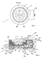
- Figur 1
- eine Querschnittsansicht durch eine erfindungsgemäße Vorrichtung, in der sich die Schließklappen in ihrer Offenstellung befinden;
- Figur 2
- eine Längsschnittansicht der in Figur 1 gezeigten Vorrichtung, in der sich die Schließklappen in ihrer Reinigungsstellung befinden;
- Figur 3
- eine perspektivische Ansicht einer Schließklappe, die mit einer Vorrichtung gemäß den Figuren 1 und 2 verwendbar ist; und
- Figur 4
- eine Teilansicht eines Anschlußrings, der in einer Vorrichtung gemäß den Figuren 1 und 2 verwendbar ist.
Claims (21)
- Vorrichtung zum Kuppeln zweier Aufbewahrungs- und/oder Fördermittel, wie in Form von Behältnissen, Containern, Rohren und/oder dergleichen, zwecks Transfer eines Produktes von einem ersten Aufbewahrungs- und/oder Fördermittel mit einer ersten Schließklappe in einem ersten Rohrstutzen (10) an einem ersten Ende und in Wirkverbindung mit zumindest einer Welle in ein zweites Aufbewahrungs- und/oder Fördermittel mit einer zweiten Schließklappe in einem zweiten Rohrstutzen (100, 100') an einem zweiten Ende und in Wirkverbindung mit der zumindest einen Welle, wobei die Schließklappen von einer Schließstellung, in der die erste Schließklappe (21) das erste Aufbewahrungs- und/oder Fördermittel an dem ersten Ende gegenüber Atmosphäre dicht abschließt, die zweite Schließklappe (121) das zweite Aufbewahrungs- und/oder Fördermittel an dem zweiten Ende gegenüber Atmosphäre dicht abschließt und die beiden Schließklappen und/oder die beiden Rohrstutzen relativ zueinander bewegbar sind, in eine Reinigungsstellung, in der die beiden Schließklappen und/oder die beiden Rohrstutzen voneinander unter Begrenzung eines mit einer Reinigungseinrichtung verbindbaren Reinigungsraums (400) beabstandet sind, sowie unter Betätigung der zumindest einen Welle in eine Offenstellung, in der die Schließklappen aufeinander aufliegen und zumindest eine Durchflußöffnung von dem ersten Aufbewahrungs- und/oder Fördermittel in das zweite Aufbewahrungs- und/oder Fördermittel für das Produkt offen ist, und von der Offenstellung in die Reinigungsstellung unter Betätigung der zumindest einen Welle sowie in die Schließstellung bewegbar sind, gekennzeichnet durch
eine erste im wesentlichen ringförmige Dichtung (25) zwischen der ersten Schließklappe (21) und dem ersten Rohrstutzen (10),
eine zweite im wesentlichen ringförmige Dichtung (125) zwischen der zweiten Schließklappe (121) und dem zweiten Rohrstutzen (100),
eine dritte im wesentlichen ringförmige Dichtung (401) zwischen dem ersten Rohrstutzen (10) und dem zweiten Rohrstutzen (100), und
eine vierte im wesentlichen ringförmige Dichtung (402) zwischen dem zweiten Rohrstutzen (100) und einem mit der zumindest einen Welle (316) kooperierenden und fest mit der zweiten Schließklappe (121) verbundenen zweiten Wellenabschnitt (126), wobei die erste, zweite, dritte und vierte Dichtungen (25, 125, 401, 402) den Reinigungsraum (400) sowohl zur Atmosphäre als auch zum Produkt abdichten. - Vorrichtung nach Anspruch 1, dadurch gekennzeichnet, daß
der erste Wellenabschnitt eine erste Halbachse (26) ist, der zweite Wellenabschnitt eine Vollachse (316) ist, die mit der zweiten Schließklappe (121) über eine zweite Halbachse (126) verbunden ist, und die erste Halbachse (26) und die zweite Halbachse (126) sich zu einer Vollachse ergänzen. - Vorrichtung nach Anspruch 1 oder 2, gekennzeichnet durch
eine Betätigungseinrichtung (300, 301, 302, 303, 304, 305, 306, 307, 314, 315, 316), über die eine Sicherungseinrichtung (2, 3, 11) zum Wechsel von der Schließstellung in eine Verriegelungsstellung, in der die beiden Aufbewahrungs- und/oder Fördermittel gegeneinander abgedichtet und die beiden Schließklappen (21, 121, 121') und/oder die beiden Rohrstutzen (10, 100, 100') fest miteinander verbunden sind, dann eine Schwenkeinrichtung (26, 126, 126') zum Wechsel von der Verriegelungsstellung in die Offenstellung sowie der Offenstellung in die Verriegelungsstellung und daraufhin die Sicherungseinrichtung zum Wechsel von der Verriegelungsstellung in die Schließstellung antreibbar sind. - Vorrichtung nach Anspruch 3, dadurch gekennzeichnet, daß
die Betätigungseinrichtung eine Getriebeeinrichtung (300, 301. 302, 303, 304, 305, 306, 307, 314, 315, 316) mit einer Antriebswelle (301) und zumindest zwei Ausgangswellen (306, 316) umfaßt, wobei die beiden Ausgangswellen (306, 316') abwechselnd von der Antriebswelle (301) ansprechbar sind. - Vorrichtung nach Anspruch 4, dadurch gekennzeichnet, daß
die Sicherungseinrichtung (2, 3, 11) einerseits mit der ersten Ausgangswelle (306) und andererseits mit den beiden Rohrstutzen (10, 100, 100') in Wirkverbindung steht, wobei die Sicherungseinrichtung (2, 3, 11) vorzugsweise ein Anschlußglied (2) zwischen dem ersten Rohrstutzen (10) und dem zweiten Rohrstutzen (100, 100') umfaßt, das zum Verriegeln der beiden Rohrstutzen (10, 100, 100') relativ zueinander oder Entriegeln derselben, insbesondere über zumindest einen Bajonettverschluß (3, 11), um eine erste Achse drehbar ist. - Vorrichtung nach Anspruch 4 oder 5, dadurch gekennzeichnet, daß
die Schwenkeinrichtung (26, 126, 126') einerseits mit der die zumindest eine Welle bildenden zweiten Ausgangswelle (316) und andererseits mit zumindest einer der beiden Schließklappen (21, 121, 121') zum Drehen der Schließklappen (21, 121, 121') um eine zweite Achse in Wirkverbindung steht, wobei die Schwenkeinrichtung vorzugsweise die beiden Halbachsen (26, 126, 126') umfaßt - Vorrichtung nach einem der Ansprüche 3 bis 6, dadurch gekennzeichnet, daß
die Reinigungsstellung sowohl zwischen der Schließstellung und der Verriegelungsstellung als auch zwischen der Offenstellung und der Verriegelungsstellung mit zumindest teilweise fest miteinander verbundenen Schließklappen (21, 121, 121') und/oder Rohrstutzen (10, 100, 100') anfahrbar ist. - Vorrichtung nach einem der Ansprüche 5 bis 7, dadurch gekennzeichnet, daß
das Anschlußglied (2) zumindest einen Vorsprung oder zumindest eine Ausnehmung (3) aufweist, und jeder Vorsprung bzw. jede Ausnehmung (3) des Anschlußglieds (2) mit einer Ausnehmung bzw. einem Vorsprung (11) des ersten Rohrstutzens (10) und/oder des zweiten Rohrstutzens in der Verriegelungsstellung fest in Eingriff steht, wobei vorzugsweise jeder Vorsprung (11) bzw. jede Ausnehmung des Anschlußgliedes (2) oder des/der Rohrstutzen(s) (10) zumindest bereichsweise einen Winkel zur ersten Achse einschließt bzw. einschließen, um die Schließklappen (21, 121, 121') durch Drehung des Anschlußglieds (2) um die erste Achse voneinander weg, insbesondere zwischen der Offenstellung und der Verriegelungsstellung, bzw. aufeinander zu, insbesondere zwischen der Schließstellung und der Verriegelungsstellung, zu bewegen. - Vorrichtung nach einem der vorangehenden Ansprüche, dadurch gekennzeichnet, daß
die erste Schließklappe (21) eine erste Stirnfläche (22) mit zumindest einer Vertiefung (23) und/oder Erhöhung aufweist, die zweite Schließklappe (121) eine zu der ersten Stirnfläche (22) komplementäre zweite Stirnfläche (122) aufweist, und die beiden Stirnflächen (22, 122) zumindest in der Offenstellung dicht aneinander anliegen, wobei vorzugsweise in der Reinigungsstellung die Stirnflächen (22, 122') im Bereich der zumindest einen Vertiefung (23) und/oder Erhöhung gegeneinander abgedichtet sind und der Reinigungsraum (400) im wesentlichen ringförmig ist. - Vorrichtung nach einem der vorangehenden Ansprüche, dadurch gekennzeichnet, daß
die erste Schließklappe (21) zumindest eine erste Ausnehmung (24) auf ihrer der ersten Stirnfläche (22) gegenüberliegenden Seite und/oder die zweite Schließklappe (121, 121') zumindest eine zweite Ausnehmung (124, 124') auf ihrer der zweiten Stirnfläche (122,122') gegenüberliegenden Seite zur Vergrößerung der Durchflußöffnung bzw. Durchflußöffnungen (200, 200') in der Offenstellung aufweist bzw. aufweisen, wobei vorzugsweise die erste Ausnehmung (24) und/oder die zweite Ausnehmung (124, 124') im wesentlichen kugelsegmentförmig ist bzw. sind. - Vorrichtung nach einem der vorangehenden Ansprüche, dadurch gekennzeichnet, daß
in der Offenstellung die erste Schließklappe (21) zumindest teilweise in Eingriff mit dem zweiten Rohrstutzen (100) und/oder die zweite Schließklappe (121, 121') zumindest teilweise in Eingriff mit dem ersten Rohrstutzen (10) ist bzw. sind. - Vorrichtung nach Anspruch 11, dadurch gekennzeichnet, daß
die erste Schließklappe (21) und/oder die zweite Schließklappe (121, 121') zumindest einen teilringförmigen Vorsprung (27, 127, 127') , vorzugsweise zwei sich gegenüberliegende teilringförmige Vorsprünge, konzentrisch zur zweiten Achse zum Eingriff in zumindest eine teilringförmige Ausnehmung (12, 102) in dem ersten Rohrstutzen (10) und/oder in dem zweiten Rohrstutzen (100) aufweist bzw. aufweisen. - Vorrichtung nach Anspruch 11, dadurch gekennzeichnet, daß
die erste Schließklappe und/oder die zweite Schließklappe zumindest eine teilringförmige Nut, vorzugsweise zwei sich gegenüberliegende teilringförmige Nuten, konzentrisch zur zweiten Achse zum Eingriff in zumindest eine teilringförmige Ausnehmung in dem ersten Rohrstutzen und/oder in dem zweiten Rohrstutzen aufweist bzw. aufweisen. - Vorrichtung nach einem der Ansprüche 6 bis 13, dadurch gekennzeichnet, daß
die zweite Achse im wesentlichen senkrecht zur ersten Achse steht. - Vorrichtung nach einem der vorangehenden Ansprüche, dadurch gekennzeichnet, daß
die erste Schließklappe (21) Bestandteil eines passiven Ventils (20) und die zweite Schließklappe (121, 121') Bestandteil eines aktiven Ventils (120) ist, wobei vorzugsweise die zweite Halbachse (126) fest mit der zweiten Ausgangswelle (316) verbunden ist - Vorrichtung nach einem der vorangehenden Ansprüche, dadurch gekennzeichnet, daß
die Reinigungseinrichtung eine Blas- und Absaugeinrichtung zum Fluten des Reinigungsraums (400) mit einem fluiden Reinigungsmittel umfaßt. - Vorrichtung nach einem der vorangehenden Ansprüche, dadurch gekennzeichnet, daß
die erste, zweite, dritte und/oder vierte Dichtung(en) resistent gegenüber Säuren und/oder Basen ist bzw. sind. - Vorrichtung nach einem der vorangehenden Ansprüche, dadurch gekennzeichnet, daß
der Reinigungsraum (400) als Schleuse wirkt. - Vorrichtung nach einem der vorangehenden Ansprüche, dadurch gekennzeichnet, daß
der Reinigungsraum (400) auf einen Druck unterhalb des Atmosphärendrucks und/oder des Drucks im Bereich der Durchflußöffnung (200, 200') bringbar ist. - Vorrichtung nach einem der vorangehenden Ansprüche, gekennzeichnet durch
eine Sensiereinheit zum Bestimmen der Produlctkonzentration im Reinigungsraum (400), insbesondere in Wirkverbindung mit der Betätigungseinrichtung (300, 301, 302, 303, 304, 305, 306, 307, 314, 315, 316). - Vorrichtung nach Anspruch 20, dadurch gekennzeichnet, daß
bei Unterschreiten eines auswählbaren Grenzwertes der bestimmten Produktkonzentration die Betätigungseinrichtung (300, 301, 302, 303, 304, 305, 306, 307, 314, 315, 316) zum Antreiben der Schließklappe (21, 121, 121') in die Schließstellung freigebbar ist.
Applications Claiming Priority (3)
| Application Number | Priority Date | Filing Date | Title |
|---|---|---|---|
| DE20014872U | 2000-08-28 | ||
| DE20014872U DE20014872U1 (de) | 2000-08-28 | 2000-08-28 | Vorrichtung zum Kuppeln zweier Aufbewahrungs- und/oder Fördermittel mit einer Reinigungseinrichtung |
| PCT/DE2001/000853 WO2002018247A1 (de) | 2000-08-28 | 2001-03-06 | Vorrichtung zum kuppeln zweier aufbewahrungs- und/oder fördermittel mit einer reinigungseinrichtung |
Publications (2)
| Publication Number | Publication Date |
|---|---|
| EP1313658A1 EP1313658A1 (de) | 2003-05-28 |
| EP1313658B1 true EP1313658B1 (de) | 2004-09-01 |
Family
ID=7945762
Family Applications (1)
| Application Number | Title | Priority Date | Filing Date |
|---|---|---|---|
| EP01915087A Expired - Lifetime EP1313658B1 (de) | 2000-08-28 | 2001-03-06 | Vorrichtung zum kuppeln zweier aufbewahrungs- und/oder fördermittel mit einer reinigungseinrichtung |
Country Status (6)
| Country | Link |
|---|---|
| US (1) | US6807979B2 (de) |
| EP (1) | EP1313658B1 (de) |
| JP (1) | JP4121850B2 (de) |
| AT (1) | ATE275084T1 (de) |
| DE (2) | DE20014872U1 (de) |
| WO (1) | WO2002018247A1 (de) |
Cited By (4)
| Publication number | Priority date | Publication date | Assignee | Title |
|---|---|---|---|---|
| EP1749770A2 (de) | 2005-08-04 | 2007-02-07 | MBE Metall-Bearbeitung Etzgen GmbH | Ventilvorrichtung zum Kuppeln von Behältnissen |
| DE102008049129A1 (de) | 2008-09-26 | 2010-04-08 | Gea Niro Gmbh | Kupplungsverschluss sowie Befestigungsmodul und Andockeinrichtung, jeweils enthaltend diesen Kupplungsverschluss |
| US8539996B2 (en) | 2007-09-28 | 2013-09-24 | Gea Pharma Systems Ag | Docking device comprising two coupling closures for the environmentally sealed transfer of bulk material, having at least one locking unit |
| DE102021134272A1 (de) | 2021-12-22 | 2023-06-22 | Andocksysteme G.Untch GmbH | Vorrichtung und Verfahren zum kontaminationsfreien Verbinden eines ersten Leitungsendes mit einem zweiten Leitungsende |
Families Citing this family (13)
| Publication number | Priority date | Publication date | Assignee | Title |
|---|---|---|---|---|
| ITLU20000007A1 (it) * | 2000-11-30 | 2002-05-30 | Mech Design Di Ing Fabrizio Bellin I E Ing Edoar | Valvola con sistema di confinamento tramite connessione di semielementi che forma con essi un unico elemento funzionale, di facile montaggio e smontaggio. |
| ITBO20010261A1 (it) * | 2001-04-27 | 2002-10-27 | Zanchetta & C Srl | Unita' e metodo per lo scarico di materiale incoerente da un dispositivo erogatore |
| DE102004003511B4 (de) * | 2004-01-23 | 2007-04-26 | Gea Niro Gmbh | Wiederverschließbarer Andockverschluss sowie Andocksystem, Mehrfachkupplungsverschluss, Mehrfachandocksystem, Fördermittel und Behältnis, enthaltend diesen Andockverschluss, und Verfahren zum Befüllen, Umfüllen und/oder Entleeren von solchen Behältnissen und/oder Fördermitteln |
| DE102005021368A1 (de) * | 2005-05-04 | 2006-11-09 | Bayer Cropscience Ag | Verfahren und Vorrichtung zur emissionsarmen Entleerung von Inhaltsstoffen aus großen Weichverpackungen |
| GB0605531D0 (en) * | 2006-03-20 | 2006-04-26 | Powder Systems Ltd | Improvements Relating To Valves |
| EP2129605B1 (de) * | 2006-12-15 | 2012-09-12 | GEA Pharma Systems AG | Kupplungsverschluss sowie andockeinrichtung, enthaltend zwei dieser kupplungsverschlüsse |
| TWM336219U (en) * | 2008-01-31 | 2008-07-11 | Gudeng Prec Industral Co Ltd | Gas filling apparatus and gas filling port thereof |
| FR2927062B1 (fr) * | 2008-02-04 | 2011-07-01 | Arkema France | Procede de remplissage securise de nanotubes de carbone, systeme de remplissage et installation industrielle mettant en oeuvre le procede. |
| DE102009025290A1 (de) * | 2009-06-15 | 2010-12-16 | Andocksysteme G. Untch Gmbh | Doppelklappenvorrichtung zum umweltdichten Verbinden zweier Behältnisse |
| EP2535630A1 (de) | 2011-06-17 | 2012-12-19 | Eaton Hydraulics SAS | Schnellverschlusskupplung mit Halbabsperrklappen |
| DE102013005226B4 (de) * | 2013-03-27 | 2017-11-16 | Krohne Messtechnik Gmbh | Messgerät |
| JP5415647B1 (ja) * | 2013-08-21 | 2014-02-12 | 株式会社ミウラ | スプリット弁 |
| US10961108B2 (en) | 2016-05-31 | 2021-03-30 | Agrotop Gmbh | Device for filling tanks with intermediate container |
Citations (2)
| Publication number | Priority date | Publication date | Assignee | Title |
|---|---|---|---|---|
| FR2640598A1 (fr) * | 1988-12-16 | 1990-06-22 | Constantin Pierre | Dispositif obturateur d'orifices de transfert de produit, notamment d'un conteneur a un autre |
| EP0619254B1 (de) * | 1993-04-01 | 1995-05-17 | ELVECO msj S.A. | Anlage und Verfahren zur Übergabe von durch Schwerkraft fliessende Produkte |
Family Cites Families (12)
| Publication number | Priority date | Publication date | Assignee | Title |
|---|---|---|---|---|
| GB888541A (en) | 1959-08-25 | 1962-01-31 | Kac Ltd | Improvements in self-sealing releasable couplings for use in fluid pressure lines |
| US5095946A (en) | 1990-01-22 | 1992-03-17 | Victaulic Company Of America | Dry-break pipe coupling |
| US5295507A (en) * | 1992-01-29 | 1994-03-22 | Eli Lilly And Company | Containment valve that allows contamination free transfer |
| DE4342962C1 (de) | 1993-12-16 | 1995-02-02 | Buck Chem Tech Werke | Vorrichtung zum Kuppeln von Behältnissen |
| FR2714709B1 (fr) * | 1994-01-05 | 1996-02-02 | Fmc Corp | Accouplement à ouverture d'urgence alimenté par une double vanne à boisseau sphérique à débordement nul. |
| DE19615646C2 (de) * | 1995-06-07 | 1997-06-26 | Glatt Systemtechnik Dresden | Kupplungseinrichtung zum Verbinden bzw. Verschließen der innerhalb zweier eigenständiger Gehäuse befindlichen Räume |
| DE19520409C1 (de) | 1995-06-09 | 1996-10-02 | Buck Chem Tech Werke | Vorrichtung zum Kuppeln von Behältnissen mit Blas- und Absaugeinrichtung |
| EP0788989A3 (de) * | 1995-09-20 | 1998-07-01 | Buck Werke GmbH & Co | Vorrichtung zum Kuppeln von Behältnissen |
| IT1309681B1 (it) * | 1999-03-29 | 2002-01-30 | Zanchetta & C Srl | Impianto per lo scarico di materiale incoerente da un contenitore |
| ITPT990016A1 (it) * | 1999-08-27 | 2001-02-27 | Salvatore Lardieri | Sistema atto a consentire il permanere delle condizioni di sterilita'del prodotto contenuto all'interno di una struttura durante l'accoppia |
| DE29915973U1 (de) | 1999-09-10 | 2001-01-25 | GEI GmbH, 79379 Müllheim | Vorrichtung zum Kuppeln zweier Behältnisse mit einer flexiblen Klappendichtung |
| US6311745B1 (en) * | 2000-06-05 | 2001-11-06 | Xerox Corporation | Systems and methods for dispensing powders |
-
2000
- 2000-08-28 DE DE20014872U patent/DE20014872U1/de not_active Expired - Lifetime
-
2001
- 2001-03-06 EP EP01915087A patent/EP1313658B1/de not_active Expired - Lifetime
- 2001-03-06 AT AT01915087T patent/ATE275084T1/de not_active IP Right Cessation
- 2001-03-06 WO PCT/DE2001/000853 patent/WO2002018247A1/de not_active Ceased
- 2001-03-06 US US10/362,041 patent/US6807979B2/en not_active Expired - Fee Related
- 2001-03-06 JP JP2002523377A patent/JP4121850B2/ja not_active Expired - Fee Related
- 2001-03-06 DE DE50103486T patent/DE50103486D1/de not_active Expired - Lifetime
Patent Citations (2)
| Publication number | Priority date | Publication date | Assignee | Title |
|---|---|---|---|---|
| FR2640598A1 (fr) * | 1988-12-16 | 1990-06-22 | Constantin Pierre | Dispositif obturateur d'orifices de transfert de produit, notamment d'un conteneur a un autre |
| EP0619254B1 (de) * | 1993-04-01 | 1995-05-17 | ELVECO msj S.A. | Anlage und Verfahren zur Übergabe von durch Schwerkraft fliessende Produkte |
Cited By (6)
| Publication number | Priority date | Publication date | Assignee | Title |
|---|---|---|---|---|
| EP1749770A2 (de) | 2005-08-04 | 2007-02-07 | MBE Metall-Bearbeitung Etzgen GmbH | Ventilvorrichtung zum Kuppeln von Behältnissen |
| US8539996B2 (en) | 2007-09-28 | 2013-09-24 | Gea Pharma Systems Ag | Docking device comprising two coupling closures for the environmentally sealed transfer of bulk material, having at least one locking unit |
| DE102008049129A1 (de) | 2008-09-26 | 2010-04-08 | Gea Niro Gmbh | Kupplungsverschluss sowie Befestigungsmodul und Andockeinrichtung, jeweils enthaltend diesen Kupplungsverschluss |
| EP2179949A2 (de) | 2008-09-26 | 2010-04-28 | GEA Niro GmbH | Kupplungsveschluss sowie Befestigungsmodul und Andockeinrichtung, jeweils enthaltend diesen Kupplungsverschluss |
| US8539995B2 (en) | 2008-09-26 | 2013-09-24 | Gea Pharma Systems Ag | Coupling lock and attachment module and docking device, each containing said coupling lock |
| DE102021134272A1 (de) | 2021-12-22 | 2023-06-22 | Andocksysteme G.Untch GmbH | Vorrichtung und Verfahren zum kontaminationsfreien Verbinden eines ersten Leitungsendes mit einem zweiten Leitungsende |
Also Published As
| Publication number | Publication date |
|---|---|
| US20040094211A1 (en) | 2004-05-20 |
| JP4121850B2 (ja) | 2008-07-23 |
| DE50103486D1 (de) | 2004-10-07 |
| DE20014872U1 (de) | 2001-01-25 |
| ATE275084T1 (de) | 2004-09-15 |
| EP1313658A1 (de) | 2003-05-28 |
| WO2002018247A1 (de) | 2002-03-07 |
| JP2004507415A (ja) | 2004-03-11 |
| US6807979B2 (en) | 2004-10-26 |
Similar Documents
| Publication | Publication Date | Title |
|---|---|---|
| EP1313658B1 (de) | Vorrichtung zum kuppeln zweier aufbewahrungs- und/oder fördermittel mit einer reinigungseinrichtung | |
| DE4342962C1 (de) | Vorrichtung zum Kuppeln von Behältnissen | |
| EP1315662B1 (de) | Vorrichtung zum kuppeln zweier aufbewahrungs- und/oder fördermittel mit einer sicherungseinrichtung | |
| DE69321378T2 (de) | Behälterventil für verschmutzungsfreie Übertragung | |
| EP2761213B1 (de) | Ventilvorrichtung und verfahren zum transferieren eines transfermediums | |
| EP2179949B1 (de) | Kupplungsveschluss sowie Befestigungsmodul und Andockeinrichtung, jeweils enthaltend diesen Kupplungsverschluss | |
| EP2443054B1 (de) | Doppelklappenvorrichtung zum umweltdichten verbinden zweier behältnisse | |
| EP2129605A2 (de) | Kupplungsverschluss sowie andockeinrichtung, enthaltend zwei dieser kupplungsverschlüsse | |
| EP0910541B1 (de) | Dichtsystem für eine schliessklappe an einer durchlassöffnung | |
| DE3874668T2 (de) | Vorrichtung zur entkuppelbaren verbindung zweier dichter hohlraeume. | |
| EP1213244A1 (de) | Doppelklappen-Andockvorrichtung | |
| EP2193092B1 (de) | Andockeinrichtung aus zwei kupplungsverschlüssen zum umweltdichten transfer von schüttgut, enthaltend mindestens eine verriegelungseinheit | |
| DE29904804U1 (de) | Automatische Verschlußvorrichtung für Kraftstofftanks | |
| EP0669123A1 (de) | Infusionsbehälter mit zwei Anschlüssen | |
| DE3407039A1 (de) | Mit absperrventil kombiniertes druckluftkupplungsteil | |
| DE202009018738U1 (de) | Leicht lösbares Kupplungssystem zur axialen Kupplung von zwei Flanschen | |
| DE69312933T2 (de) | Vorrichtung zum transport von flüssigkeiten mittels schwerkraft einer pumpe | |
| DE202025100230U1 (de) | Containment-Klappe für den Transfer von pharmazeutischen Materialien | |
| DE2263397A1 (de) | Kupplung | |
| DE102019131680B4 (de) | Andockverschluss und Verfahren zum kontaminationsfreien Verbinden eines ersten Hohlraums mit einem zweiten Hohlraum | |
| DE10023968B4 (de) | Vorrichtung zum Kuppeln von zwei Behältnissen | |
| DE3313257A1 (de) | Schnellverschlusskupplung | |
| DE602005005011T2 (de) | Klappenventil mit Blockiereinrichtung | |
| DE202007013675U1 (de) | Entnahme- und Transportwerkzeug | |
| DE3901576A1 (de) | Verschlussvorrichtung |
Legal Events
| Date | Code | Title | Description |
|---|---|---|---|
| PUAI | Public reference made under article 153(3) epc to a published international application that has entered the european phase |
Free format text: ORIGINAL CODE: 0009012 |
|
| AK | Designated contracting states |
Designated state(s): AT BE CH CY DE DK ES FI FR GB GR IE IT LI LU MC NL PT SE TR |
|
| 17P | Request for examination filed |
Effective date: 20030123 |
|
| RIN1 | Information on inventor provided before grant (corrected) |
Inventor name: MOELLER, KLAUS Inventor name: KOCH, MARTIN Inventor name: ELSAESSER, BERND |
|
| TPAC | Observations filed by third parties |
Free format text: ORIGINAL CODE: EPIDOSNTIPA |
|
| GRAP | Despatch of communication of intention to grant a patent |
Free format text: ORIGINAL CODE: EPIDOSNIGR1 |
|
| GRAS | Grant fee paid |
Free format text: ORIGINAL CODE: EPIDOSNIGR3 |
|
| GRAA | (expected) grant |
Free format text: ORIGINAL CODE: 0009210 |
|
| AK | Designated contracting states |
Kind code of ref document: B1 Designated state(s): AT BE CH CY DE DK ES FI FR GB GR IE IT LI LU MC NL PT SE TR |
|
| PG25 | Lapsed in a contracting state [announced via postgrant information from national office to epo] |
Ref country code: FI Free format text: LAPSE BECAUSE OF FAILURE TO SUBMIT A TRANSLATION OF THE DESCRIPTION OR TO PAY THE FEE WITHIN THE PRESCRIBED TIME-LIMIT Effective date: 20040901 Ref country code: TR Free format text: LAPSE BECAUSE OF FAILURE TO SUBMIT A TRANSLATION OF THE DESCRIPTION OR TO PAY THE FEE WITHIN THE PRESCRIBED TIME-LIMIT Effective date: 20040901 Ref country code: NL Free format text: LAPSE BECAUSE OF FAILURE TO SUBMIT A TRANSLATION OF THE DESCRIPTION OR TO PAY THE FEE WITHIN THE PRESCRIBED TIME-LIMIT Effective date: 20040901 Ref country code: ES Free format text: LAPSE BECAUSE OF FAILURE TO SUBMIT A TRANSLATION OF THE DESCRIPTION OR TO PAY THE FEE WITHIN THE PRESCRIBED TIME-LIMIT Effective date: 20040901 |
|
| REG | Reference to a national code |
Ref country code: GB Ref legal event code: FG4D Free format text: NOT ENGLISH |
|
| REG | Reference to a national code |
Ref country code: CH Ref legal event code: EP |
|
| GBT | Gb: translation of ep patent filed (gb section 77(6)(a)/1977) |
Effective date: 20040901 |
|
| REG | Reference to a national code |
Ref country code: IE Ref legal event code: FG4D Free format text: GERMAN |
|
| REF | Corresponds to: |
Ref document number: 50103486 Country of ref document: DE Date of ref document: 20041007 Kind code of ref document: P |
|
| REG | Reference to a national code |
Ref country code: CH Ref legal event code: NV Representative=s name: NOVAGRAAF INTERNATIONAL SA |
|
| PG25 | Lapsed in a contracting state [announced via postgrant information from national office to epo] |
Ref country code: SE Free format text: LAPSE BECAUSE OF FAILURE TO SUBMIT A TRANSLATION OF THE DESCRIPTION OR TO PAY THE FEE WITHIN THE PRESCRIBED TIME-LIMIT Effective date: 20041201 Ref country code: GR Free format text: LAPSE BECAUSE OF FAILURE TO SUBMIT A TRANSLATION OF THE DESCRIPTION OR TO PAY THE FEE WITHIN THE PRESCRIBED TIME-LIMIT Effective date: 20041201 Ref country code: DK Free format text: LAPSE BECAUSE OF FAILURE TO SUBMIT A TRANSLATION OF THE DESCRIPTION OR TO PAY THE FEE WITHIN THE PRESCRIBED TIME-LIMIT Effective date: 20041201 |
|
| NLV1 | Nl: lapsed or annulled due to failure to fulfill the requirements of art. 29p and 29m of the patents act | ||
| PG25 | Lapsed in a contracting state [announced via postgrant information from national office to epo] |
Ref country code: CY Free format text: LAPSE BECAUSE OF FAILURE TO SUBMIT A TRANSLATION OF THE DESCRIPTION OR TO PAY THE FEE WITHIN THE PRESCRIBED TIME-LIMIT Effective date: 20050306 Ref country code: AT Free format text: LAPSE BECAUSE OF NON-PAYMENT OF DUE FEES Effective date: 20050306 Ref country code: LU Free format text: LAPSE BECAUSE OF NON-PAYMENT OF DUE FEES Effective date: 20050306 |
|
| ET | Fr: translation filed | ||
| PG25 | Lapsed in a contracting state [announced via postgrant information from national office to epo] |
Ref country code: MC Free format text: LAPSE BECAUSE OF NON-PAYMENT OF DUE FEES Effective date: 20050331 |
|
| PLBE | No opposition filed within time limit |
Free format text: ORIGINAL CODE: 0009261 |
|
| STAA | Information on the status of an ep patent application or granted ep patent |
Free format text: STATUS: NO OPPOSITION FILED WITHIN TIME LIMIT |
|
| 26N | No opposition filed |
Effective date: 20050602 |
|
| REG | Reference to a national code |
Ref country code: CH Ref legal event code: PFA Owner name: GEA NIRO GMBH Free format text: GEA BUCK VALVE GMBH#MAUCHENER STRASSE 14#79379 MUELLHEIM (DE) -TRANSFER TO- GEA NIRO GMBH#MAUCHENER STRASSE 14#79379 MUELLHEIM (DE) |
|
| REG | Reference to a national code |
Ref country code: FR Ref legal event code: CD |
|
| PG25 | Lapsed in a contracting state [announced via postgrant information from national office to epo] |
Ref country code: PT Free format text: LAPSE BECAUSE OF NON-PAYMENT OF DUE FEES Effective date: 20050201 |
|
| REG | Reference to a national code |
Ref country code: CH Ref legal event code: NV Representative=s name: E. BLUM & CO. AG PATENT- UND MARKENANWAELTE VSP Ref country code: CH Ref legal event code: PUE Owner name: GEA PHARMA SYSTEMS AG Free format text: GEA NIRO GMBH#MAUCHENER STRASSE 14#79379 MUELLHEIM (DE) -TRANSFER TO- GEA PHARMA SYSTEMS AG#HAUPTSTRASSE 145#4416 BUBENDORF (CH) |
|
| REG | Reference to a national code |
Ref country code: GB Ref legal event code: 732E Free format text: REGISTERED BETWEEN 20100819 AND 20100825 |
|
| BECA | Be: change of holder's address |
Owner name: GEA PHARMA SYSTEMS A.G.HAUPTSTRASSE 145, CH-4416 B Effective date: 20100917 |
|
| BECH | Be: change of holder |
Owner name: GEA PHARMA SYSTEMS A.G. Effective date: 20100917 |
|
| REG | Reference to a national code |
Ref country code: FR Ref legal event code: TP |
|
| PGFP | Annual fee paid to national office [announced via postgrant information from national office to epo] |
Ref country code: FR Payment date: 20120319 Year of fee payment: 12 Ref country code: IE Payment date: 20120312 Year of fee payment: 12 |
|
| PGFP | Annual fee paid to national office [announced via postgrant information from national office to epo] |
Ref country code: IT Payment date: 20120320 Year of fee payment: 12 Ref country code: BE Payment date: 20120328 Year of fee payment: 12 |
|
| BERE | Be: lapsed |
Owner name: GEA PHARMA SYSTEMS A.G. Effective date: 20130331 |
|
| REG | Reference to a national code |
Ref country code: FR Ref legal event code: ST Effective date: 20131129 |
|
| REG | Reference to a national code |
Ref country code: IE Ref legal event code: MM4A |
|
| PG25 | Lapsed in a contracting state [announced via postgrant information from national office to epo] |
Ref country code: IE Free format text: LAPSE BECAUSE OF NON-PAYMENT OF DUE FEES Effective date: 20130306 Ref country code: FR Free format text: LAPSE BECAUSE OF NON-PAYMENT OF DUE FEES Effective date: 20130402 Ref country code: BE Free format text: LAPSE BECAUSE OF NON-PAYMENT OF DUE FEES Effective date: 20130331 |
|
| PG25 | Lapsed in a contracting state [announced via postgrant information from national office to epo] |
Ref country code: IT Free format text: LAPSE BECAUSE OF NON-PAYMENT OF DUE FEES Effective date: 20130306 |
|
| PGFP | Annual fee paid to national office [announced via postgrant information from national office to epo] |
Ref country code: GB Payment date: 20200325 Year of fee payment: 20 |
|
| PGFP | Annual fee paid to national office [announced via postgrant information from national office to epo] |
Ref country code: CH Payment date: 20200326 Year of fee payment: 20 |
|
| PGFP | Annual fee paid to national office [announced via postgrant information from national office to epo] |
Ref country code: DE Payment date: 20200331 Year of fee payment: 20 |
|
| REG | Reference to a national code |
Ref country code: DE Ref legal event code: R071 Ref document number: 50103486 Country of ref document: DE |
|
| REG | Reference to a national code |
Ref country code: CH Ref legal event code: PL |
|
| REG | Reference to a national code |
Ref country code: GB Ref legal event code: PE20 Expiry date: 20210305 |
|
| PG25 | Lapsed in a contracting state [announced via postgrant information from national office to epo] |
Ref country code: GB Free format text: LAPSE BECAUSE OF EXPIRATION OF PROTECTION Effective date: 20210305 |