EP1314832A1 - Screen structure including bend - Google Patents
Screen structure including bend Download PDFInfo
- Publication number
- EP1314832A1 EP1314832A1 EP01870254A EP01870254A EP1314832A1 EP 1314832 A1 EP1314832 A1 EP 1314832A1 EP 01870254 A EP01870254 A EP 01870254A EP 01870254 A EP01870254 A EP 01870254A EP 1314832 A1 EP1314832 A1 EP 1314832A1
- Authority
- EP
- European Patent Office
- Prior art keywords
- parts
- straight
- wheels
- end member
- hinge joint
- Prior art date
- Legal status (The legal status is an assumption and is not a legal conclusion. Google has not performed a legal analysis and makes no representation as to the accuracy of the status listed.)
- Granted
Links
- 238000005096 rolling process Methods 0.000 claims abstract description 12
- 230000007704 transition Effects 0.000 description 8
- 230000035939 shock Effects 0.000 description 3
- 238000010276 construction Methods 0.000 description 2
- 230000001627 detrimental effect Effects 0.000 description 1
- 230000000694 effects Effects 0.000 description 1
- 239000004744 fabric Substances 0.000 description 1
- 239000002184 metal Substances 0.000 description 1
- 230000002028 premature Effects 0.000 description 1
- 239000004753 textile Substances 0.000 description 1
Images


Classifications
-
- E—FIXED CONSTRUCTIONS
- E04—BUILDING
- E04F—FINISHING WORK ON BUILDINGS, e.g. STAIRS, FLOORS
- E04F10/00—Sunshades, e.g. Florentine blinds or jalousies; Outside screens; Awnings or baldachins
- E04F10/02—Sunshades, e.g. Florentine blinds or jalousies; Outside screens; Awnings or baldachins of flexible canopy materials, e.g. canvas ; Baldachins
- E04F10/06—Sunshades, e.g. Florentine blinds or jalousies; Outside screens; Awnings or baldachins of flexible canopy materials, e.g. canvas ; Baldachins comprising a roller-blind with means for holding the end away from a building
- E04F10/0666—Accessories
- E04F10/067—Accessories acting as intermediate support of the flexible canopy
-
- E—FIXED CONSTRUCTIONS
- E04—BUILDING
- E04F—FINISHING WORK ON BUILDINGS, e.g. STAIRS, FLOORS
- E04F10/00—Sunshades, e.g. Florentine blinds or jalousies; Outside screens; Awnings or baldachins
- E04F10/02—Sunshades, e.g. Florentine blinds or jalousies; Outside screens; Awnings or baldachins of flexible canopy materials, e.g. canvas ; Baldachins
- E04F10/06—Sunshades, e.g. Florentine blinds or jalousies; Outside screens; Awnings or baldachins of flexible canopy materials, e.g. canvas ; Baldachins comprising a roller-blind with means for holding the end away from a building
- E04F10/0607—Sunshades, e.g. Florentine blinds or jalousies; Outside screens; Awnings or baldachins of flexible canopy materials, e.g. canvas ; Baldachins comprising a roller-blind with means for holding the end away from a building with guiding-sections for supporting the movable end of the blind
-
- E—FIXED CONSTRUCTIONS
- E04—BUILDING
- E04F—FINISHING WORK ON BUILDINGS, e.g. STAIRS, FLOORS
- E04F10/00—Sunshades, e.g. Florentine blinds or jalousies; Outside screens; Awnings or baldachins
- E04F10/02—Sunshades, e.g. Florentine blinds or jalousies; Outside screens; Awnings or baldachins of flexible canopy materials, e.g. canvas ; Baldachins
- E04F10/06—Sunshades, e.g. Florentine blinds or jalousies; Outside screens; Awnings or baldachins of flexible canopy materials, e.g. canvas ; Baldachins comprising a roller-blind with means for holding the end away from a building
- E04F10/0644—Sunshades, e.g. Florentine blinds or jalousies; Outside screens; Awnings or baldachins of flexible canopy materials, e.g. canvas ; Baldachins comprising a roller-blind with means for holding the end away from a building with mechanisms for unrolling or balancing the blind
- E04F10/0655—Sunshades, e.g. Florentine blinds or jalousies; Outside screens; Awnings or baldachins of flexible canopy materials, e.g. canvas ; Baldachins comprising a roller-blind with means for holding the end away from a building with mechanisms for unrolling or balancing the blind acting on the movable end, e.g. front bar
Definitions
- the present invention is related to screen structures, in particular roller blinds used as awnings and the like. It is more specifically related to roller blinds which make a bend, preferably over a variable angle.
- Document EP-A-0918118 is presented as the closest prior art. It concerns a screen structure, comprising two guides for accommodating between them an end member to which a screen is attached. The screen can - at the other end - be rolled up onto a drum.
- Each guide comprises straight parts and a hinge joint which is arranged between said straight parts.
- the hinge joint comprises a central shell part and two adjoining side shell parts, which execute a controlled movement with respect to the central shell part. Due to the specific hinge design, the side shell parts are forced to be placed symmetrically with respect to the central shell part, at any angle of the hinge joint.
- the end member is attached to wheeled carriages which roll on tracks on the insides of the straight guide parts and inside the hinge joint.
- the wheels must necessarily roll over a transition from a track inside the straight guide to a track inside the joint and again when moving from the joint to the adjacent straight guide. This is a problematic item of all prior art designs. Due to the variability of the joint's angle, it is impossible to provide a smooth transition of the wheels from the straight guide to the joint and vice versa. In most positions of the joint, this transition will occur with an irregularity in the carriage movement, or a shock, which is detrimental in terms of wear and user friendliness of the structure.
- the present invention aims to provide a screen structure with a variable bend, wherein a perfectly smooth movement of the screen through the bend is possible, i.e. without any irregularity or shock of that movement.
- the present invention is related to a screen structure comprising a set of at least two guide members and at least one end member, said end member being guided at its edges by said guide members, a screen being attached to said end member, each of said guide members comprising a first straight part and at least one additional straight part, each of said guide members further comprising at least one hinge joint between two adjacent straight parts, said hinge joint comprising a plurality of shell parts, of which at least two are connected to said straight guide parts, characterised in that :
- said first means for rolling or gliding is a first set of wheels
- said second means for rolling or gliding is a second set of wheels
- said second set of wheels are placed on the same set of axes as said first set of wheels.
- said hinge joint preferably comprises three shell parts, one central shell part and two side shell parts, said side shell parts being rigidly attached to said straight guide parts, and said side shell parts being able to rotate with respect to said central part and wherein three guiding plates are present, a central guiding plate attached to said central shell part, and two side plates attached to said side shell parts.
- the screen structure of the invention preferably comprises a pulling chord or belt and a plurality of guide rolls inside said hinge joint, for guiding said chord or belt.
- said second set of wheels preferably has a U-shaped outer profile.
- connection between a shell part and a straight guide part takes place by two extensions of said shell part, said extensions fitting into hollow spaces inside said straight guide part, the first extension lying to one side of an axis around which torsion of said straight guide part is possible, the other extension lying to the opposite side.
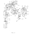
- Fig. 1 represents a view of a screen structure according to the invention.
- Fig. 2 represents a detailed view of the hinge joint according to the invention.
- FIG. 3 represents an exploded version of the view of figure 2
- Fig. 4 represents a view of the main characteristic parts of the end member according to the invention.
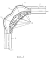
- Fig. 5 and 6 show side views of the hinge joint of the invention, installed at 90°.
- Fig. 7 describes the profile of the straight guide parts according to the invention.
- a screen structure of the invention is shown in figure 1. It comprises two parallel guides 1, of which one is shown in the drawing. Each guide consists of two straight parts 2 and 3 with a variable-angle hinge joint 4 in between. A support roll 5 is present between two joints 4, and carried in bearings which allow rotation of the roll 5 with respect to the joints.
- the screen (not shown), which is normally a textile cloth, is wound onto a drum 6.
- the drum 6 and/or the guides 1 may be attached to a rigid structure, such as a wall, a veranda, or other.
- One free end of the screen is then attached to an end member 7, placed in between the guides 1.
- the end member 7 can be moved whilst remaining essentially parallel to the drum 6, thereby unrolling or rolling up the screen, equivalent to closing or opening it.
- the pulling and retracting of the screen can be done by a motor which drives the drum 6 and by cables, tapes, or chords present inside the guides 1 and attached to the end member 7. Also, tensioning springs are present for keeping the screen in a tensioned condition during the movement.
- the screen structure of the invention is characterised by a specific design of the hinge joint 4, which is present in each of the parallel guides 1, and which in the case of figure 1 is a variable angle joint.
- the invention is also related to the design of the end member 7 and the means for guiding said end member 7 through the guides 1 and the joint 4 of the invention.
- the invention is further characterised by an improved connection between the hinge joint 4 and the straight guide parts 2 and 3, in order to have a better resistance against torsional forces.
- Figures 2 and 3 show a preferred embodiment of the hinge joint 4 in more detail.
- Figure 4 shows the parts of the end member 7 which are essential to the invention.
- the joint 4 comprises two identical (but mirrored) side shells 10, attached to the straight guide parts 2, 3 to form projected extensions of said straight parts. In between these two projected shells 10, is the central shell 11.
- the projected shells 10 are attached rigidly to the straight guide parts 2 and 3, by means of extensions 32 which fit into hollow portions of the straight guides 2 and 3.
- An additional extension 33 is present on the projected shells 10 for obstructing torsional movement between the straight parts 2 and 3 and the projected shells 10. This is explained in more detail later in the text.
- the projected shells 10, and with them, the straight guide parts 2 and 3, are connected to the central shell 11 by way of screws 34, which leave the possibility of a rotation, around axes 12, of the straight parts 2 and 3, relative to the central shell 11.
- an angle between the straight guide parts 2 and 3 can be installed.
- This angle preferably lies between 90° and 180°.
- the mininum angle that can be installed may be lower than 90°, for example around 70°.
- caps 13 At the top of the projected shells 10 and the central shell 11 are caps 13, which may overlap to a degree, according to the desired angle between the straight guide parts 2 and 3. Guide rolls 16 are present inside the joint, for guiding the pulling chord 17.
- a central guiding plate 20 On the inner vertical side of the joint, are three guiding plates, for example metal plates : a central guiding plate 20 and two side plates 21. These plates form a characteristic of the invention.
- the central plate 20 is attached to the central shell 11, while the two side plates 21 are attached to the projected shells 10.
- the side plates 21 and central plate 20 overlap over a circular area 18, the centre of which coincides with the rotational axis 12.
- the side plates 21 are attached to the side shells 10 by screws 35.
- the central plate 20 At their section point with the axis 12, the central plate 20 is attached to the central shell part 11, via the screws 36, which are screwed into the hollow end of the screws 34.
- the side plate 20 and central plates 21 comprise circular portions 40 which lie adjacent to each other and which have their centre point in the centre of area 18.
- the side plates 21 can make the same rotational movement as the side shells 10, with respect to the central plate 20 and central shell 11, respectively.
- the thickness of the overlapping portion 18 of the side plates 21 is preferably smaller than the thickness of the rest of the side plates 21.
- the central plate 20 has an opening 30 for carrying the support roll 5. In the opening 30, a bearing 45 is present for allowing the support roll 5 to rotate.
- the function of the guiding plates 20, 21 is to ensure a smooth transition of the end member 7 through the hinge joint 4.
- the end member 7 is equipped with a triple set of wheels.
- the primary set of two wheels 22 serves to move the end member 7 through the straight guide parts 2 and 3. This is shown in figure 2, where the end member 7 is positioned in the upper part of the screen structure, above the joint 4.
- the wheels 22 are forced to roll in tracks 24 on the inside of the guide parts 2 and 3.
- the second set of wheels 23 shares the same axes 25 with the first set 22 and is placed between said first set 22 and the end member body.
- a third set of wheels 28, placed between the first and second set serves as a guide for the pulling chord 17, which runs inside the guides 1 and the end member 7.
- the wheel 26 which is placed in the opening 27, is used for guiding the pulling chord into the end member 7, towards the spring (not shown) which is placed inside this end member.
- the invention is characterised by the presence of the second set of wheels 23.
- This second set of wheels 23 is placed in such a way that they take over the function of carrying the end member 7 as soon as this end member enters the joint 4.
- the end member enters the joint 4 at point 38 (see figure 5).
- the secondary wheels 23 land onto the first guiding plate 21 and roll consecutively over this plate, the central plate 20 and the opposite side plate, until the end member 7 leaves the joint, at which point the support of the end member is taken over again by the primary wheels 22.
- the secondary wheels 23 may have a cylindrical shape.
- the diameter of the wheels 23, and of the third set 28 is preferably smaller than that of the primary wheels 22, so that while the end member is supported by the straight guide parts 2 or 3, these wheels 23 and 28 do not make contact with the inside of said guide parts.
- the side view of figure 5 illustrates the smooth transition from the straight part 2 to the joint 4.
- the top ridge 41 of the side plates 21 has a slightly curved shape, in order to gradually lift up the end member by the secondary support wheels 23.
- the shape of this top ridge 41 defines the moment when the carrying function is transferred from the primary wheels 22 to the secondary wheels 23.
- the primary wheels 22 In order to have a smooth transition, the primary wheels 22 must support the end member at least until the moment when the secondary wheels 23 have made contact with the guiding plates 21.
- the guiding plates have a shape which allows a smooth and shock-free transition through the joint, i.e. from one guiding plate to the adjacent one.
- the top ridges of the assembled guiding plates 20, 21 form a continuous curve, as the top of the side plates 21 is always tangent to the top of the central plate 20.
- the present invention also covers guiding plates which do not overlap, but are fully adjacent to each other.
- the plates are made of the same thickness and their shape, as seen in a section perpendicular to the rotation axis is defined by the visible parts of the plates described above, and shown for example in figure 5.
- the guiding plates 20,21 also perform the function of closing off - at least partially - the hinge joint on the inside. In this way, the hinge joint 4 is protected on all sides from the surrounding environment.
- An indicator 31 is present on the inside of the side shells 10. This gives an indication of the relative position of the side shells 10, and thus also of the straight guide parts 2 and 3, with respect to the central shell part 11. As can be understood from the construction, the side shells 10 are not necessarily symmetric with respect to the central part. This set-up allows a more flexible positioning of the screen.
- the guide rolls 16 are also a characterising feature.
- the cable or belt often runs on flat surfaces inside the joint, which is a cause for excessive wear of this belt and of said flat surfaces.
- a chord is used in stead of a belt.
- the chord now only makes contact with the guide rolls' limited surface, which helps to avoid premature wear of the chord.
- Figure 6 shows a view of how this chord runs through the joint. The use of a belt in stead of a chord is not excluded by the present invention.
- the second set of wheels 23 which run on top of the guiding plates can have a separate axis, which is not identical with the axis of the first set of wheels 22.
- Figure 7 shows the profile of the straight guide parts 2 and 3 according to the preferred embodiment.
- the area 50 corresponds to the place where the extensions 32 of the side shell parts fit.
- Area 51 is the area into which the additional extension 33 fits.
- the position of area 51 is such that it is placed on the opposite side of any axis around which torsional forces operate on the interface between straight guide parts 2, 3 and the hinge joint 4. This feature allows therefore a better resistance to such torsional forces.
- a screen structure which is generally characterised by the combination of the vertical guiding plates 20, 21 and the secondary set of wheels 23.
- This can be done in a hinge joint of another design, for example having a single rotational axis, as will be appreciated by anyone skilled in the art.
- the invention is therefore not limited to the particular design as described above and as shown in the drawings. It is also possible to have a screen with more than two guide members 1 and/or to have more than two straight guide parts (2,3) in each guide member and to provide hinge joints according to the invention, between adjacent guide parts.
- the end member 7 may be designed - still according to the invention - so that it glides over the guiding plates, in stead of rolling over it.
- the wheels 23 may be replaced by fixed cylinders or other structures, or they may be left out altogether, leaving the bare axes 25 to glide over the guiding plates 20 and 21.
Landscapes
- Engineering & Computer Science (AREA)
- Architecture (AREA)
- Civil Engineering (AREA)
- Structural Engineering (AREA)
- Operating, Guiding And Securing Of Roll- Type Closing Members (AREA)
- Walking Sticks, Umbrellas, And Fans (AREA)
- Extensible Doors And Revolving Doors (AREA)
Abstract
- said hinge joint (4) further comprises a plurality of guiding plates (20,21) placed in an essentially vertical position, the assembled top ridges of said guiding plates forming a continuous curve, in every position of said two adjacent straight guide parts (2,3),
- said end member (7) comprises a first means (22) for rolling or gliding in said straight guide parts (2,3), and a second means (23) for rolling or gliding on the top ridge of said guiding plates (20,21) of said hinge joint (4).
Description
- The present invention is related to screen structures, in particular roller blinds used as awnings and the like. It is more specifically related to roller blinds which make a bend, preferably over a variable angle.
- Document EP-A-0918118 is presented as the closest prior art. It concerns a screen structure, comprising two guides for accommodating between them an end member to which a screen is attached. The screen can - at the other end - be rolled up onto a drum. Each guide comprises straight parts and a hinge joint which is arranged between said straight parts. The hinge joint comprises a central shell part and two adjoining side shell parts, which execute a controlled movement with respect to the central shell part. Due to the specific hinge design, the side shell parts are forced to be placed symmetrically with respect to the central shell part, at any angle of the hinge joint.
- In the above cited document, the end member is attached to wheeled carriages which roll on tracks on the insides of the straight guide parts and inside the hinge joint. The wheels must necessarily roll over a transition from a track inside the straight guide to a track inside the joint and again when moving from the joint to the adjacent straight guide. This is a problematic item of all prior art designs. Due to the variability of the joint's angle, it is impossible to provide a smooth transition of the wheels from the straight guide to the joint and vice versa. In most positions of the joint, this transition will occur with an irregularity in the carriage movement, or a shock, which is detrimental in terms of wear and user friendliness of the structure.
- Another problem of prior art designs is that they are insufficiently protected from torsional movement of the straight guide parts with respect to the hinge joint.
- The present invention aims to provide a screen structure with a variable bend, wherein a perfectly smooth movement of the screen through the bend is possible, i.e. without any irregularity or shock of that movement.
- It is a further aim of the invention to provide a screen structure having straight guide parts with improved resistance to torsional forces.
- The present invention is related to a screen structure comprising a set of at least two guide members and at least one end member, said end member being guided at its edges by said guide members, a screen being attached to said end member, each of said guide members comprising a first straight part and at least one additional straight part, each of said guide members further comprising at least one hinge joint between two adjacent straight parts, said hinge joint comprising a plurality of shell parts, of which at least two are connected to said straight guide parts, characterised in that :
- said hinge joint further comprises a plurality of guiding plates placed in an essentially vertical position, the assembled top ridges of said guiding plates forming a continuous curve, in every position of said two adjacent straight guide parts,
- said end member comprises a first means for rolling or gliding in said straight guide parts, and a second means for rolling or gliding on the top ridge of said guiding plates.
- According to the preferred embodiment of the present invention, said first means for rolling or gliding is a first set of wheels, and wherein said second means for rolling or gliding is a second set of wheels.
- Preferably, said second set of wheels are placed on the same set of axes as said first set of wheels.
- According to the invention, said hinge joint preferably comprises three shell parts, one central shell part and two side shell parts, said side shell parts being rigidly attached to said straight guide parts, and said side shell parts being able to rotate with respect to said central part and wherein three guiding plates are present, a central guiding plate attached to said central shell part, and two side plates attached to said side shell parts.
- The screen structure of the invention preferably comprises a pulling chord or belt and a plurality of guide rolls inside said hinge joint, for guiding said chord or belt.
- Furthermore, said second set of wheels preferably has a U-shaped outer profile.
- In the preferred embodiment of the screen structure according to the invention, the connection between a shell part and a straight guide part takes place by two extensions of said shell part, said extensions fitting into hollow spaces inside said straight guide part, the first extension lying to one side of an axis around which torsion of said straight guide part is possible, the other extension lying to the opposite side.
- Fig. 1 represents a view of a screen structure according to the invention.
- Fig. 2 represents a detailed view of the hinge joint according to the invention.
- Fig. 3 represents an exploded version of the view of figure 2
- Fig. 4 represents a view of the main characteristic parts of the end member according to the invention.
- Fig. 5 and 6 show side views of the hinge joint of the invention, installed at 90°.
- Fig. 7 describes the profile of the straight guide parts according to the invention.
- A screen structure of the invention is shown in figure 1. It comprises two
parallel guides 1, of which one is shown in the drawing. Each guide consists of twostraight parts angle hinge joint 4 in between. Asupport roll 5 is present between twojoints 4, and carried in bearings which allow rotation of theroll 5 with respect to the joints. The screen (not shown), which is normally a textile cloth, is wound onto a drum 6. The drum 6 and/or theguides 1 may be attached to a rigid structure, such as a wall, a veranda, or other. One free end of the screen is then attached to anend member 7, placed in between theguides 1. Theend member 7 can be moved whilst remaining essentially parallel to the drum 6, thereby unrolling or rolling up the screen, equivalent to closing or opening it. The pulling and retracting of the screen can be done by a motor which drives the drum 6 and by cables, tapes, or chords present inside theguides 1 and attached to theend member 7. Also, tensioning springs are present for keeping the screen in a tensioned condition during the movement. The features described so far are known in the art. - The screen structure of the invention is characterised by a specific design of the
hinge joint 4, which is present in each of theparallel guides 1, and which in the case of figure 1 is a variable angle joint. The invention is also related to the design of theend member 7 and the means for guiding saidend member 7 through theguides 1 and thejoint 4 of the invention. The invention is further characterised by an improved connection between thehinge joint 4 and thestraight guide parts - Figures 2 and 3 show a preferred embodiment of the
hinge joint 4 in more detail. Figure 4 shows the parts of theend member 7 which are essential to the invention. As seen in figures 2 and 3, thejoint 4 comprises two identical (but mirrored)side shells 10, attached to thestraight guide parts shells 10, is thecentral shell 11. The projectedshells 10 are attached rigidly to thestraight guide parts extensions 32 which fit into hollow portions of thestraight guides additional extension 33 is present on the projectedshells 10 for obstructing torsional movement between thestraight parts shells 10. This is explained in more detail later in the text. - The projected
shells 10, and with them, thestraight guide parts central shell 11 by way ofscrews 34, which leave the possibility of a rotation, aroundaxes 12, of thestraight parts central shell 11. In this way an angle between thestraight guide parts - At the top of the projected
shells 10 and thecentral shell 11 arecaps 13, which may overlap to a degree, according to the desired angle between thestraight guide parts Guide rolls 16 are present inside the joint, for guiding thepulling chord 17. - On the inner vertical side of the joint, are three guiding plates, for example metal plates : a central guiding
plate 20 and twoside plates 21. These plates form a characteristic of the invention. Thecentral plate 20 is attached to thecentral shell 11, while the twoside plates 21 are attached to the projectedshells 10. Theside plates 21 andcentral plate 20 overlap over acircular area 18, the centre of which coincides with therotational axis 12. Theside plates 21 are attached to theside shells 10 byscrews 35. At their section point with theaxis 12, thecentral plate 20 is attached to thecentral shell part 11, via thescrews 36, which are screwed into the hollow end of thescrews 34. Theside plate 20 andcentral plates 21 comprisecircular portions 40 which lie adjacent to each other and which have their centre point in the centre ofarea 18. In this way, theside plates 21 can make the same rotational movement as theside shells 10, with respect to thecentral plate 20 andcentral shell 11, respectively. The thickness of the overlappingportion 18 of theside plates 21 is preferably smaller than the thickness of the rest of theside plates 21. Thecentral plate 20 has anopening 30 for carrying thesupport roll 5. In theopening 30, abearing 45 is present for allowing thesupport roll 5 to rotate. - The function of the guiding
plates end member 7 through thehinge joint 4. In figure 4, it is seen that theend member 7 is equipped with a triple set of wheels. The primary set of twowheels 22 serves to move theend member 7 through thestraight guide parts end member 7 is positioned in the upper part of the screen structure, above thejoint 4. Thewheels 22 are forced to roll intracks 24 on the inside of theguide parts wheels 23 shares thesame axes 25 with thefirst set 22 and is placed between said first set 22 and the end member body. A third set ofwheels 28, placed between the first and second set serves as a guide for the pullingchord 17, which runs inside theguides 1 and theend member 7. Thewheel 26 which is placed in theopening 27, is used for guiding the pulling chord into theend member 7, towards the spring (not shown) which is placed inside this end member. - The invention is characterised by the presence of the second set of
wheels 23. This second set ofwheels 23 is placed in such a way that they take over the function of carrying theend member 7 as soon as this end member enters the joint 4. When moving for example from top to bottom, the end member enters the joint 4 at point 38 (see figure 5). Simultaneous with or immediately after this point, thesecondary wheels 23 land onto the first guidingplate 21 and roll consecutively over this plate, thecentral plate 20 and the opposite side plate, until theend member 7 leaves the joint, at which point the support of the end member is taken over again by theprimary wheels 22. As seen on figure 4, thesecondary wheels 23 may have a cylindrical shape. They may have another profile, for example a U-shaped profile, similar to the profile of thecable supporting wheels 28, which will ensure a firmer grip of thesewheels 23 on top of thenarrow guiding plates wheels 23, and of thethird set 28 is preferably smaller than that of theprimary wheels 22, so that while the end member is supported by thestraight guide parts wheels - As soon as the
secondary wheels 23 have made contact with the guiding plates, theprimary wheels 22 are no longer supported. In fact, inside the joint, there is no track at all for these primary wheels, who are carried 'in flight' until they make contact again with the track of the next straight guide part. The side view of figure 5 illustrates the smooth transition from thestraight part 2 to thejoint 4. Thetop ridge 41 of theside plates 21 has a slightly curved shape, in order to gradually lift up the end member by thesecondary support wheels 23. The shape of thistop ridge 41 defines the moment when the carrying function is transferred from theprimary wheels 22 to thesecondary wheels 23. In order to have a smooth transition, theprimary wheels 22 must support the end member at least until the moment when thesecondary wheels 23 have made contact with the guidingplates 21. - As seen in figure 5, the guiding plates have a shape which allows a smooth and shock-free transition through the joint, i.e. from one guiding plate to the adjacent one. In every position (every angle), the top ridges of the assembled guiding
plates side plates 21 is always tangent to the top of thecentral plate 20. An added advantage is due to the fact that inside the joint, no track is present for the primary wheels, so more space is available inside the joint for the passing of the pullingchord 17. The absence of tracks inside the joints allows thewheels 22 to move through the joint without any shocks taking place. - As an alternative to the overlapping
guiding plates - The guiding
plates hinge joint 4 is protected on all sides from the surrounding environment. - Some additional features of the preferred embodiment can be derived from the figures. An
indicator 31 is present on the inside of theside shells 10. This gives an indication of the relative position of theside shells 10, and thus also of thestraight guide parts central shell part 11. As can be understood from the construction, theside shells 10 are not necessarily symmetric with respect to the central part. This set-up allows a more flexible positioning of the screen. - The guide rolls 16 are also a characterising feature. In prior art designs, the cable or belt often runs on flat surfaces inside the joint, which is a cause for excessive wear of this belt and of said flat surfaces. Because of the lack of supporting tracks inside the shells, there is room for these guide rolls 16, which allow a much smoother transition of the
chord 17. According to the preferred embodiment, a chord is used in stead of a belt. In fact, inside the joint, the chord now only makes contact with the guide rolls' limited surface, which helps to avoid premature wear of the chord. Figure 6 shows a view of how this chord runs through the joint. The use of a belt in stead of a chord is not excluded by the present invention. - According to an alternative embodiment of the present invention, the second set of
wheels 23 which run on top of the guiding plates can have a separate axis, which is not identical with the axis of the first set ofwheels 22. - Figure 7 shows the profile of the
straight guide parts area 50 corresponds to the place where theextensions 32 of the side shell parts fit.Area 51 is the area into which theadditional extension 33 fits. The position ofarea 51 is such that it is placed on the opposite side of any axis around which torsional forces operate on the interface betweenstraight guide parts hinge joint 4. This feature allows therefore a better resistance to such torsional forces. - It is emphasised that the above describes a screen structure which is generally characterised by the combination of the
vertical guiding plates wheels 23. This can be done in a hinge joint of another design, for example having a single rotational axis, as will be appreciated by anyone skilled in the art. The invention is therefore not limited to the particular design as described above and as shown in the drawings. It is also possible to have a screen with more than twoguide members 1 and/or to have more than two straight guide parts (2,3) in each guide member and to provide hinge joints according to the invention, between adjacent guide parts. - As another alternative, the
end member 7 may be designed - still according to the invention - so that it glides over the guiding plates, in stead of rolling over it. To that effect, thewheels 23 may be replaced by fixed cylinders or other structures, or they may be left out altogether, leaving thebare axes 25 to glide over the guidingplates
Claims (7)
- A screen structure comprising a set of at least two guide members (1) and at least one end member (7), said end member (7) being guided at its edges by said guide members (1), a screen being attached to said end member (7), each of said guide members (1) comprising a first straight part (2) and at least one additional straight part (3), each of said guide members (1) further comprising at least one hinge joint (4) between two adjacent straight parts (2,3), said hinge joint comprising a plurality of shell parts (10,11), of which at least two are connected to said straight guide parts (2,3), characterised in that :said hinge joint (4) further comprises a plurality of guiding plates (20,21) placed in an essentially vertical position, the assembled top ridges of said guiding plates forming a continuous curve, in every position of said two adjacent straight guide parts (2,3),said end member (7) comprises a first means for rolling or gliding in said straight guide parts (2,3), and a second means for rolling or gliding on the top ridge of said guiding plates (20,21).
- A screen structure according to claim 1, wherein said first means for rolling or gliding is a first set of wheels (22), and wherein said second means for rolling or gliding is a second set of wheels (23).
- A screen structure according to claim 2, wherein said second set of wheels (23) are placed on the same set of axes (25) as said first set of wheels.
- A screen structure according to any one of claims 1 to 3, wherein said hinge joint (4) comprises three shell parts, one central shell part (11) and two side shell parts (10) , said side shell parts (10) being rigidly attached to said straight guide parts (2,3), and said side shell parts (10) being able to rotate with respect to said central part (11) and wherein three guiding plates are present, a central guiding plate (20) attached to said central shell part (11), and two side plates (21) attached to said side shell parts (10).
- A screen structure according to any one of claims 1 to 4, comprising a pulling chord or belt (17) and a plurality of guide rolls (16) inside said hinge joint (4), for guiding said chord or belt(17).
- A screen structure according to any one of claims 2 to 5, wherein said second set of wheels (23) has a U-shaped outer profile.
- A screen structure according to any one of the preceding claims, wherein the connection between a shell part (10) and a straight guide part takes place by two extensions (32,33) of said shell part, said extensions fitting into hollow spaces (50,51) inside said straight guide part, the first extension (32) lying to one side of an axis around which torsion of said straight guide part is possible, the other extension (33) lying to the opposite side.
Priority Applications (3)
| Application Number | Priority Date | Filing Date | Title |
|---|---|---|---|
| DE60129447T DE60129447T2 (en) | 2001-11-22 | 2001-11-22 | Umbrella frame with an angle piece |
| EP01870254A EP1314832B1 (en) | 2001-11-22 | 2001-11-22 | Screen structure including bend |
| AT01870254T ATE367493T1 (en) | 2001-11-22 | 2001-11-22 | UMBRELLA SUPPORT WITH AN ANGLE PIECE |
Applications Claiming Priority (1)
| Application Number | Priority Date | Filing Date | Title |
|---|---|---|---|
| EP01870254A EP1314832B1 (en) | 2001-11-22 | 2001-11-22 | Screen structure including bend |
Publications (2)
| Publication Number | Publication Date |
|---|---|
| EP1314832A1 true EP1314832A1 (en) | 2003-05-28 |
| EP1314832B1 EP1314832B1 (en) | 2007-07-18 |
Family
ID=8185052
Family Applications (1)
| Application Number | Title | Priority Date | Filing Date |
|---|---|---|---|
| EP01870254A Expired - Lifetime EP1314832B1 (en) | 2001-11-22 | 2001-11-22 | Screen structure including bend |
Country Status (3)
| Country | Link |
|---|---|
| EP (1) | EP1314832B1 (en) |
| AT (1) | ATE367493T1 (en) |
| DE (1) | DE60129447T2 (en) |
Cited By (1)
| Publication number | Priority date | Publication date | Assignee | Title |
|---|---|---|---|---|
| EP2136013A3 (en) * | 2008-06-20 | 2013-10-02 | Weinor GmbH & Co. KG | Awning |
Citations (2)
| Publication number | Priority date | Publication date | Assignee | Title |
|---|---|---|---|---|
| EP0608720A1 (en) * | 1993-01-28 | 1994-08-03 | LOSBERGER SONNENSCHUTZ GmbH & Co. | Adjustable arcuate deviation for awning and shading installation |
| EP0918118A1 (en) | 1997-11-19 | 1999-05-26 | Theodorus Bernardus Wolters | Screen structure |
-
2001
- 2001-11-22 AT AT01870254T patent/ATE367493T1/en not_active IP Right Cessation
- 2001-11-22 EP EP01870254A patent/EP1314832B1/en not_active Expired - Lifetime
- 2001-11-22 DE DE60129447T patent/DE60129447T2/en not_active Expired - Lifetime
Patent Citations (2)
| Publication number | Priority date | Publication date | Assignee | Title |
|---|---|---|---|---|
| EP0608720A1 (en) * | 1993-01-28 | 1994-08-03 | LOSBERGER SONNENSCHUTZ GmbH & Co. | Adjustable arcuate deviation for awning and shading installation |
| EP0918118A1 (en) | 1997-11-19 | 1999-05-26 | Theodorus Bernardus Wolters | Screen structure |
Cited By (1)
| Publication number | Priority date | Publication date | Assignee | Title |
|---|---|---|---|---|
| EP2136013A3 (en) * | 2008-06-20 | 2013-10-02 | Weinor GmbH & Co. KG | Awning |
Also Published As
| Publication number | Publication date |
|---|---|
| DE60129447T2 (en) | 2008-06-19 |
| ATE367493T1 (en) | 2007-08-15 |
| DE60129447D1 (en) | 2007-08-30 |
| EP1314832B1 (en) | 2007-07-18 |
Similar Documents
| Publication | Publication Date | Title |
|---|---|---|
| US11619092B2 (en) | Wheel carriage assembly with telescoping hembar | |
| EP3133235B1 (en) | Shading device for an architectural opening and method for adjusting an end stop position of the shading device | |
| US5522446A (en) | Sectional overhead door | |
| CN107599953B (en) | Awning device | |
| TW442612B (en) | Wrap spring shade operator | |
| US9915094B2 (en) | Roller shutter for opening and closing a doorway | |
| KR100476090B1 (en) | Monitor | |
| US10954689B2 (en) | Awning apparatus | |
| US7850026B2 (en) | Crane assembly | |
| EP1108839A2 (en) | Sectional overhead door and apparatus for making door panels | |
| US20190257388A1 (en) | High-speed stroke-type moving device with a supply line, and power transmission chain herefor | |
| CN102858209B (en) | For the driving balladeur train of sliding curtain | |
| US20210131178A1 (en) | Door, in particular spiral door | |
| EP1314832B1 (en) | Screen structure including bend | |
| JP2013169879A (en) | Airplane passenger boarding bridge having stepless path | |
| EP0956408A1 (en) | Awning with pressure-compensating support | |
| US20100269292A1 (en) | Block and tackle window balance device | |
| FI60056C (en) | BALANSERINGSANORDNING FOER KIPPDOERRAR | |
| KR101739967B1 (en) | Dual cable reel | |
| US20050139331A1 (en) | Overhead door apparatus with enclosed counterbalance mechanism | |
| EP3990733B1 (en) | Concealed lever hinge for doors, in particular reinforced hinged doors, as well as door system comprising such hinge | |
| USRE33216E (en) | Blind assembly | |
| US7168686B2 (en) | Lifting apparatus | |
| EP3713835B1 (en) | Jalousi wall assembly for a passenger bridge | |
| EP1413701B1 (en) | Safety device for a sectional closing element, such as a door, a main door, a gate or suchlike |
Legal Events
| Date | Code | Title | Description |
|---|---|---|---|
| PUAI | Public reference made under article 153(3) epc to a published international application that has entered the european phase |
Free format text: ORIGINAL CODE: 0009012 |
|
| AK | Designated contracting states |
Designated state(s): AT BE CH CY DE DK ES FI FR GB GR IE IT LI LU MC NL PT SE TR |
|
| AX | Request for extension of the european patent |
Extension state: AL LT LV MK RO SI |
|
| 17P | Request for examination filed |
Effective date: 20030716 |
|
| AKX | Designation fees paid |
Designated state(s): AT BE CH CY DE DK ES FI FR GB GR IE IT LI LU MC NL PT SE TR |
|
| GRAP | Despatch of communication of intention to grant a patent |
Free format text: ORIGINAL CODE: EPIDOSNIGR1 |
|
| GRAS | Grant fee paid |
Free format text: ORIGINAL CODE: EPIDOSNIGR3 |
|
| GRAA | (expected) grant |
Free format text: ORIGINAL CODE: 0009210 |
|
| AK | Designated contracting states |
Kind code of ref document: B1 Designated state(s): AT BE CH CY DE DK ES FI FR GB GR IE IT LI LU MC NL PT SE TR |
|
| REG | Reference to a national code |
Ref country code: GB Ref legal event code: FG4D |
|
| REG | Reference to a national code |
Ref country code: CH Ref legal event code: EP |
|
| REF | Corresponds to: |
Ref document number: 60129447 Country of ref document: DE Date of ref document: 20070830 Kind code of ref document: P |
|
| REG | Reference to a national code |
Ref country code: IE Ref legal event code: FG4D |
|
| PG25 | Lapsed in a contracting state [announced via postgrant information from national office to epo] |
Ref country code: FI Free format text: LAPSE BECAUSE OF FAILURE TO SUBMIT A TRANSLATION OF THE DESCRIPTION OR TO PAY THE FEE WITHIN THE PRESCRIBED TIME-LIMIT Effective date: 20070718 Ref country code: ES Free format text: LAPSE BECAUSE OF FAILURE TO SUBMIT A TRANSLATION OF THE DESCRIPTION OR TO PAY THE FEE WITHIN THE PRESCRIBED TIME-LIMIT Effective date: 20071029 Ref country code: PT Free format text: LAPSE BECAUSE OF FAILURE TO SUBMIT A TRANSLATION OF THE DESCRIPTION OR TO PAY THE FEE WITHIN THE PRESCRIBED TIME-LIMIT Effective date: 20071218 |
|
| REG | Reference to a national code |
Ref country code: CH Ref legal event code: PL |
|
| ET | Fr: translation filed | ||
| PG25 | Lapsed in a contracting state [announced via postgrant information from national office to epo] |
Ref country code: CH Free format text: LAPSE BECAUSE OF FAILURE TO SUBMIT A TRANSLATION OF THE DESCRIPTION OR TO PAY THE FEE WITHIN THE PRESCRIBED TIME-LIMIT Effective date: 20070718 Ref country code: LI Free format text: LAPSE BECAUSE OF FAILURE TO SUBMIT A TRANSLATION OF THE DESCRIPTION OR TO PAY THE FEE WITHIN THE PRESCRIBED TIME-LIMIT Effective date: 20070718 Ref country code: AT Free format text: LAPSE BECAUSE OF FAILURE TO SUBMIT A TRANSLATION OF THE DESCRIPTION OR TO PAY THE FEE WITHIN THE PRESCRIBED TIME-LIMIT Effective date: 20070718 |
|
| PG25 | Lapsed in a contracting state [announced via postgrant information from national office to epo] |
Ref country code: DK Free format text: LAPSE BECAUSE OF FAILURE TO SUBMIT A TRANSLATION OF THE DESCRIPTION OR TO PAY THE FEE WITHIN THE PRESCRIBED TIME-LIMIT Effective date: 20070718 Ref country code: GR Free format text: LAPSE BECAUSE OF FAILURE TO SUBMIT A TRANSLATION OF THE DESCRIPTION OR TO PAY THE FEE WITHIN THE PRESCRIBED TIME-LIMIT Effective date: 20071019 |
|
| RAP2 | Party data changed (patent owner data changed or rights of a patent transferred) |
Owner name: HAROL CONSYST N.V. |
|
| PLBE | No opposition filed within time limit |
Free format text: ORIGINAL CODE: 0009261 |
|
| STAA | Information on the status of an ep patent application or granted ep patent |
Free format text: STATUS: NO OPPOSITION FILED WITHIN TIME LIMIT |
|
| 26N | No opposition filed |
Effective date: 20080421 |
|
| PG25 | Lapsed in a contracting state [announced via postgrant information from national office to epo] |
Ref country code: SE Free format text: LAPSE BECAUSE OF FAILURE TO SUBMIT A TRANSLATION OF THE DESCRIPTION OR TO PAY THE FEE WITHIN THE PRESCRIBED TIME-LIMIT Effective date: 20071018 Ref country code: MC Free format text: LAPSE BECAUSE OF NON-PAYMENT OF DUE FEES Effective date: 20071130 |
|
| NLT2 | Nl: modifications (of names), taken from the european patent patent bulletin |
Owner name: HAROL CONSYST N.V. Effective date: 20080514 |
|
| GBPC | Gb: european patent ceased through non-payment of renewal fee |
Effective date: 20071122 |
|
| PG25 | Lapsed in a contracting state [announced via postgrant information from national office to epo] |
Ref country code: IE Free format text: LAPSE BECAUSE OF NON-PAYMENT OF DUE FEES Effective date: 20071122 |
|
| PG25 | Lapsed in a contracting state [announced via postgrant information from national office to epo] |
Ref country code: GB Free format text: LAPSE BECAUSE OF NON-PAYMENT OF DUE FEES Effective date: 20071122 |
|
| PG25 | Lapsed in a contracting state [announced via postgrant information from national office to epo] |
Ref country code: CY Free format text: LAPSE BECAUSE OF FAILURE TO SUBMIT A TRANSLATION OF THE DESCRIPTION OR TO PAY THE FEE WITHIN THE PRESCRIBED TIME-LIMIT Effective date: 20070718 |
|
| PG25 | Lapsed in a contracting state [announced via postgrant information from national office to epo] |
Ref country code: TR Free format text: LAPSE BECAUSE OF FAILURE TO SUBMIT A TRANSLATION OF THE DESCRIPTION OR TO PAY THE FEE WITHIN THE PRESCRIBED TIME-LIMIT Effective date: 20070718 |
|
| PG25 | Lapsed in a contracting state [announced via postgrant information from national office to epo] |
Ref country code: IT Free format text: LAPSE BECAUSE OF NON-PAYMENT OF DUE FEES Effective date: 20071130 |
|
| PGFP | Annual fee paid to national office [announced via postgrant information from national office to epo] |
Ref country code: LU Payment date: 20131024 Year of fee payment: 13 Ref country code: DE Payment date: 20131022 Year of fee payment: 13 Ref country code: FR Payment date: 20131121 Year of fee payment: 13 Ref country code: BE Payment date: 20131022 Year of fee payment: 13 |
|
| PGFP | Annual fee paid to national office [announced via postgrant information from national office to epo] |
Ref country code: NL Payment date: 20131023 Year of fee payment: 13 |
|
| REG | Reference to a national code |
Ref country code: DE Ref legal event code: R119 Ref document number: 60129447 Country of ref document: DE |
|
| REG | Reference to a national code |
Ref country code: NL Ref legal event code: V1 Effective date: 20150601 |
|
| PG25 | Lapsed in a contracting state [announced via postgrant information from national office to epo] |
Ref country code: BE Free format text: LAPSE BECAUSE OF NON-PAYMENT OF DUE FEES Effective date: 20141130 Ref country code: LU Free format text: LAPSE BECAUSE OF NON-PAYMENT OF DUE FEES Effective date: 20141122 |
|
| REG | Reference to a national code |
Ref country code: FR Ref legal event code: ST Effective date: 20150731 |
|
| PG25 | Lapsed in a contracting state [announced via postgrant information from national office to epo] |
Ref country code: NL Free format text: LAPSE BECAUSE OF NON-PAYMENT OF DUE FEES Effective date: 20150601 |
|
| PG25 | Lapsed in a contracting state [announced via postgrant information from national office to epo] |
Ref country code: DE Free format text: LAPSE BECAUSE OF NON-PAYMENT OF DUE FEES Effective date: 20150602 |
|
| PG25 | Lapsed in a contracting state [announced via postgrant information from national office to epo] |
Ref country code: FR Free format text: LAPSE BECAUSE OF NON-PAYMENT OF DUE FEES Effective date: 20141201 |