EP1319536A1 - Klimatisierungseinrichtung für ein Fahrzeug - Google Patents
Klimatisierungseinrichtung für ein Fahrzeug Download PDFInfo
- Publication number
- EP1319536A1 EP1319536A1 EP02023655A EP02023655A EP1319536A1 EP 1319536 A1 EP1319536 A1 EP 1319536A1 EP 02023655 A EP02023655 A EP 02023655A EP 02023655 A EP02023655 A EP 02023655A EP 1319536 A1 EP1319536 A1 EP 1319536A1
- Authority
- EP
- European Patent Office
- Prior art keywords
- compressor
- module
- drive
- heat exchanger
- carbon dioxide
- Prior art date
- Legal status (The legal status is an assumption and is not a legal conclusion. Google has not performed a legal analysis and makes no representation as to the accuracy of the status listed.)
- Granted
Links
Images

Classifications
-
- B—PERFORMING OPERATIONS; TRANSPORTING
- B60—VEHICLES IN GENERAL
- B60H—ARRANGEMENTS OF HEATING, COOLING, VENTILATING OR OTHER AIR-TREATING DEVICES SPECIALLY ADAPTED FOR PASSENGER OR GOODS SPACES OF VEHICLES
- B60H1/00—Heating, cooling or ventilating devices
- B60H1/32—Cooling devices
- B60H1/3204—Cooling devices using compression
- B60H1/3226—Self-contained devices, i.e. including own drive motor
-
- B—PERFORMING OPERATIONS; TRANSPORTING
- B60—VEHICLES IN GENERAL
- B60H—ARRANGEMENTS OF HEATING, COOLING, VENTILATING OR OTHER AIR-TREATING DEVICES SPECIALLY ADAPTED FOR PASSENGER OR GOODS SPACES OF VEHICLES
- B60H1/00—Heating, cooling or ventilating devices
- B60H1/00357—Air-conditioning arrangements specially adapted for particular vehicles
- B60H1/00371—Air-conditioning arrangements specially adapted for particular vehicles for vehicles carrying large numbers of passengers, e.g. buses
-
- B—PERFORMING OPERATIONS; TRANSPORTING
- B60—VEHICLES IN GENERAL
- B60H—ARRANGEMENTS OF HEATING, COOLING, VENTILATING OR OTHER AIR-TREATING DEVICES SPECIALLY ADAPTED FOR PASSENGER OR GOODS SPACES OF VEHICLES
- B60H1/00—Heating, cooling or ventilating devices
- B60H1/00507—Details, e.g. mounting arrangements, desaeration devices
- B60H1/00514—Details of air conditioning housings
- B60H1/00542—Modular assemblies
-
- B—PERFORMING OPERATIONS; TRANSPORTING
- B60—VEHICLES IN GENERAL
- B60H—ARRANGEMENTS OF HEATING, COOLING, VENTILATING OR OTHER AIR-TREATING DEVICES SPECIALLY ADAPTED FOR PASSENGER OR GOODS SPACES OF VEHICLES
- B60H1/00—Heating, cooling or ventilating devices
- B60H1/00642—Control systems or circuits; Control members or indication devices for heating, cooling or ventilating devices
- B60H1/00814—Control systems or circuits characterised by their output, for controlling particular components of the heating, cooling or ventilating installation
- B60H1/00878—Control systems or circuits characterised by their output, for controlling particular components of the heating, cooling or ventilating installation the components being temperature regulating devices
- B60H1/00899—Controlling the flow of liquid in a heat pump system
-
- B—PERFORMING OPERATIONS; TRANSPORTING
- B60—VEHICLES IN GENERAL
- B60L—PROPULSION OF ELECTRICALLY-PROPELLED VEHICLES; SUPPLYING ELECTRIC POWER FOR AUXILIARY EQUIPMENT OF ELECTRICALLY-PROPELLED VEHICLES; ELECTRODYNAMIC BRAKE SYSTEMS FOR VEHICLES IN GENERAL; MAGNETIC SUSPENSION OR LEVITATION FOR VEHICLES; MONITORING OPERATING VARIABLES OF ELECTRICALLY-PROPELLED VEHICLES; ELECTRIC SAFETY DEVICES FOR ELECTRICALLY-PROPELLED VEHICLES
- B60L1/00—Supplying electric power to auxiliary equipment of vehicles
- B60L1/003—Supplying electric power to auxiliary equipment of vehicles to auxiliary motors, e.g. for pumps, compressors
-
- B—PERFORMING OPERATIONS; TRANSPORTING
- B60—VEHICLES IN GENERAL
- B60L—PROPULSION OF ELECTRICALLY-PROPELLED VEHICLES; SUPPLYING ELECTRIC POWER FOR AUXILIARY EQUIPMENT OF ELECTRICALLY-PROPELLED VEHICLES; ELECTRODYNAMIC BRAKE SYSTEMS FOR VEHICLES IN GENERAL; MAGNETIC SUSPENSION OR LEVITATION FOR VEHICLES; MONITORING OPERATING VARIABLES OF ELECTRICALLY-PROPELLED VEHICLES; ELECTRIC SAFETY DEVICES FOR ELECTRICALLY-PROPELLED VEHICLES
- B60L1/00—Supplying electric power to auxiliary equipment of vehicles
- B60L1/02—Supplying electric power to auxiliary equipment of vehicles to electric heating circuits
-
- F—MECHANICAL ENGINEERING; LIGHTING; HEATING; WEAPONS; BLASTING
- F25—REFRIGERATION OR COOLING; COMBINED HEATING AND REFRIGERATION SYSTEMS; HEAT PUMP SYSTEMS; MANUFACTURE OR STORAGE OF ICE; LIQUEFACTION SOLIDIFICATION OF GASES
- F25B—REFRIGERATION MACHINES, PLANTS OR SYSTEMS; COMBINED HEATING AND REFRIGERATION SYSTEMS; HEAT PUMP SYSTEMS
- F25B9/00—Compression machines, plants or systems, in which the refrigerant is air or other gas of low boiling point
- F25B9/002—Compression machines, plants or systems, in which the refrigerant is air or other gas of low boiling point characterised by the refrigerant
- F25B9/008—Compression machines, plants or systems, in which the refrigerant is air or other gas of low boiling point characterised by the refrigerant the refrigerant being carbon dioxide
-
- B—PERFORMING OPERATIONS; TRANSPORTING
- B60—VEHICLES IN GENERAL
- B60H—ARRANGEMENTS OF HEATING, COOLING, VENTILATING OR OTHER AIR-TREATING DEVICES SPECIALLY ADAPTED FOR PASSENGER OR GOODS SPACES OF VEHICLES
- B60H1/00—Heating, cooling or ventilating devices
- B60H1/00007—Combined heating, ventilating, or cooling devices
- B60H1/00207—Combined heating, ventilating, or cooling devices characterised by the position of the HVAC devices with respect to the passenger compartment
- B60H2001/00235—Devices in the roof area of the passenger compartment
-
- B—PERFORMING OPERATIONS; TRANSPORTING
- B60—VEHICLES IN GENERAL
- B60L—PROPULSION OF ELECTRICALLY-PROPELLED VEHICLES; SUPPLYING ELECTRIC POWER FOR AUXILIARY EQUIPMENT OF ELECTRICALLY-PROPELLED VEHICLES; ELECTRODYNAMIC BRAKE SYSTEMS FOR VEHICLES IN GENERAL; MAGNETIC SUSPENSION OR LEVITATION FOR VEHICLES; MONITORING OPERATING VARIABLES OF ELECTRICALLY-PROPELLED VEHICLES; ELECTRIC SAFETY DEVICES FOR ELECTRICALLY-PROPELLED VEHICLES
- B60L2200/00—Type of vehicles
- B60L2200/18—Buses
-
- B—PERFORMING OPERATIONS; TRANSPORTING
- B60—VEHICLES IN GENERAL
- B60L—PROPULSION OF ELECTRICALLY-PROPELLED VEHICLES; SUPPLYING ELECTRIC POWER FOR AUXILIARY EQUIPMENT OF ELECTRICALLY-PROPELLED VEHICLES; ELECTRODYNAMIC BRAKE SYSTEMS FOR VEHICLES IN GENERAL; MAGNETIC SUSPENSION OR LEVITATION FOR VEHICLES; MONITORING OPERATING VARIABLES OF ELECTRICALLY-PROPELLED VEHICLES; ELECTRIC SAFETY DEVICES FOR ELECTRICALLY-PROPELLED VEHICLES
- B60L2240/00—Control parameters of input or output; Target parameters
- B60L2240/10—Vehicle control parameters
- B60L2240/34—Cabin temperature
-
- B—PERFORMING OPERATIONS; TRANSPORTING
- B60—VEHICLES IN GENERAL
- B60L—PROPULSION OF ELECTRICALLY-PROPELLED VEHICLES; SUPPLYING ELECTRIC POWER FOR AUXILIARY EQUIPMENT OF ELECTRICALLY-PROPELLED VEHICLES; ELECTRODYNAMIC BRAKE SYSTEMS FOR VEHICLES IN GENERAL; MAGNETIC SUSPENSION OR LEVITATION FOR VEHICLES; MONITORING OPERATING VARIABLES OF ELECTRICALLY-PROPELLED VEHICLES; ELECTRIC SAFETY DEVICES FOR ELECTRICALLY-PROPELLED VEHICLES
- B60L2240/00—Control parameters of input or output; Target parameters
- B60L2240/10—Vehicle control parameters
- B60L2240/36—Temperature of vehicle components or parts
-
- B—PERFORMING OPERATIONS; TRANSPORTING
- B60—VEHICLES IN GENERAL
- B60L—PROPULSION OF ELECTRICALLY-PROPELLED VEHICLES; SUPPLYING ELECTRIC POWER FOR AUXILIARY EQUIPMENT OF ELECTRICALLY-PROPELLED VEHICLES; ELECTRODYNAMIC BRAKE SYSTEMS FOR VEHICLES IN GENERAL; MAGNETIC SUSPENSION OR LEVITATION FOR VEHICLES; MONITORING OPERATING VARIABLES OF ELECTRICALLY-PROPELLED VEHICLES; ELECTRIC SAFETY DEVICES FOR ELECTRICALLY-PROPELLED VEHICLES
- B60L2270/00—Problem solutions or means not otherwise provided for
- B60L2270/46—Heat pumps, e.g. for cabin heating
-
- F—MECHANICAL ENGINEERING; LIGHTING; HEATING; WEAPONS; BLASTING
- F25—REFRIGERATION OR COOLING; COMBINED HEATING AND REFRIGERATION SYSTEMS; HEAT PUMP SYSTEMS; MANUFACTURE OR STORAGE OF ICE; LIQUEFACTION SOLIDIFICATION OF GASES
- F25B—REFRIGERATION MACHINES, PLANTS OR SYSTEMS; COMBINED HEATING AND REFRIGERATION SYSTEMS; HEAT PUMP SYSTEMS
- F25B2309/00—Gas cycle refrigeration machines
- F25B2309/06—Compression machines, plants or systems characterised by the refrigerant being carbon dioxide
- F25B2309/061—Compression machines, plants or systems characterised by the refrigerant being carbon dioxide with cycle highest pressure above the supercritical pressure
-
- Y—GENERAL TAGGING OF NEW TECHNOLOGICAL DEVELOPMENTS; GENERAL TAGGING OF CROSS-SECTIONAL TECHNOLOGIES SPANNING OVER SEVERAL SECTIONS OF THE IPC; TECHNICAL SUBJECTS COVERED BY FORMER USPC CROSS-REFERENCE ART COLLECTIONS [XRACs] AND DIGESTS
- Y10—TECHNICAL SUBJECTS COVERED BY FORMER USPC
- Y10S—TECHNICAL SUBJECTS COVERED BY FORMER USPC CROSS-REFERENCE ART COLLECTIONS [XRACs] AND DIGESTS
- Y10S62/00—Refrigeration
- Y10S62/02—Refrigerant pumps
Definitions
- the invention relates to an air conditioning device for a vehicle, with a Compressors with a compressor drive, an interior heat exchanger, one Expansion device, and an outdoor heat exchanger and possibly an internal Heat exchanger.
- 31 045 C2 is an air conditioning system for arrangement on the roof of a Motor vehicle known that has an evaporator and a condenser, the arranged in a housing to be mounted on the roof and by cables with each other and with a compressor connected to a Drive device is drivable.
- the case has on its underside at least one outlet opening for the cooled air generated in the air conditioning system on, the housing for sealing arrangement on the roof of the Motor vehicle on its underside with a circumferential sealing edge is provided.
- the housing is fastened to the roof of the Motor vehicle releasably attached.
- the compressor and the drive device for the compressor are arranged in the housing of the air conditioning system.
- Air conditioning is a standard air conditioning system with R134a is operated.
- R 134a systems can be Efficiency and construction volume still leave nothing to be desired. With R 134a systems are above In addition, comfortably high air temperatures for interior heating Vehicle such as a minibus, a minibus or a large omnibus practically inaccessible in heat pump operation, so that R 134a Heat pump circuits for vehicle heating are currently not standard be used.
- WO 97 27 437 A1 describes a compression refrigeration system with a Compressor, a gas cooler, an expansion device and an evaporator, which are connected to each other in a circuit in which a refrigerant is included.
- the degree of filling is Refrigerant between 50 and 100% of the critical density of the refrigerant.
- the refrigerant is preferably formed by carbon dioxide.
- a system with a heat pump and a storage tank is known from EP 0 969 255 A2 known.
- the heat pump has a compressor, a high temperature heat exchanger, an expansion device and one Low temperature heat exchanger connected in a circle and are traversed by carbon dioxide as a working fluid.
- the high temperature heat exchanger is in the bottom area of the temperature stratified Storage arranged and as a countercurrent heat exchanger in a container intended.
- a riser pipe connects to this container with a riser pipe outlet to the upper area of the storage tank extends.
- the high temperature heat exchanger is preferably as Lamellar tube bundle heat exchanger designed. In the riser can Regulation of the volume flow of the storage fluid to be heated Control device may be provided.
- DE 100 06 513 A 1 discloses an air conditioning system for a motor vehicle with a refrigerant circuit, a coolant circuit, a refrigerant / coolant heat exchanger that couples these circuits in a heat-transferring manner and means for operating-mode-dependent control of the refrigerant flow, the air conditioning system in addition to an air conditioning operating mode at least also in one Heat pump or reheat mode is operable.
- the refrigerant / coolant heat exchanger in the coolant circuit is preceded, at least in the heat pump operating mode, by an internal combustion engine exhaust gas coolant / heat exchanger and / or the refrigerant / coolant heat exchanger functions in reheat mode as a condenser / gas cooler connected upstream of a supply air / coolant heat exchanger.
- a drying operating mode can be provided for drying the supply air / refrigerant heat exchanger with the air direction reversed.
- R 134a or CO 2 is used as the refrigerant in this air conditioning system.
- the compressor of the refrigerant circuit is mechanically coupled to the internal combustion engine.
- DE 198 06 654 A1 describes an air conditioning system for vehicles with a duct network which, by switching two flow distributors, enables two operating circuits having a common compressor and common expansion devices, one of which is used for cooling and the other for heating the passenger compartment of a motor vehicle.
- the heating circuit enables the passenger compartment to be heated very quickly, even when the internal combustion engine of the motor vehicle is cold, since the circulating heat carrier in the compressor is heated to a maximum heating temperature without inertia.
- the duct network provided for cooling the internal combustion engine is suitable as a heat source for heating, for which both duct networks are coupled via a common heat exchanger. CO 2 is used as the heat transfer medium.
- the compressor has a fixed, ie clutchless drive connection with the internal combustion engine of the vehicle.
- a method and a device for heating and cooling the useful space of a motor vehicle driven by a fuel juice machine is known from EP 0 945 290 A2.
- a circulating medium is passed through a compressor, an ambient heat exchanger, a throttle device and an interior heat exchanger, which are connected in series and form an integral closed circuit.
- a supercritical pressure is generated on the high pressure side of the circuit and a subcritical pressure is simultaneously generated on the low pressure side of the circuit.
- the high-pressure side of the circuit In heating mode, the high-pressure side of the circuit generates a subcritical pressure.
- the high pressure side of the circuit becomes the low pressure side in cooling mode and the low pressure side of the circuit becomes the high pressure side in cooling mode.
- the circulating medium is guided in the interior heat exchanger at a supercritical pressure, thermal energy being transferred from the circulating medium to the usable space air to be supplied to the usable space.
- the circulating medium is also passed through an exhaust gas heat exchanger.
- the circulating medium is preferably formed by CO 2 .
- the compressor is driven by the internal combustion engine.
- the invention has for its object an air conditioning device to create the type mentioned, for cooling in refrigeration and for Heating provided in heat pump operation and compared to standard i.e. R 134a systems improved performance and efficiency with reduced Has construction volume.
- the device is designed as a self-sufficient flat module, which in a cooling mode for cooling and in a heat pump mode for Heating is provided, the compressor being a carbon dioxide compressor high performance and small size and with the compressor drive in the module is integrated, the module having only one power connection Has energy form for energy supply to the drive of the module.
- the carbon dioxide compressor is preferably an external one capacity controlled compressor.
- the carbon dioxide compressor preferably has a diameter of about 100 to 120 mm, so that a low-building module is feasible ..
- the carbon dioxide refrigeration technology offers advantages that allow small flat ones Realize modules that are suitable for optimal cooling in cold operation and to heat efficiently in heat pump operation. Own carbon dioxide compressors with a small build volume, a high performance, so that it with the associated Compressor drive can be integrated in a climate module.
- the compressor drive can be formed by an electric motor. It can be be a DC motor or a three-phase motor.
- Compressor drive can be a hermetic drive, a Semi-hermetic drive or an open belt drive.
- to Energy supply of the device is only an external electrical energy connection required on the module.
- the electrical power supply to the module can a vehicle with an internal combustion engine e.g. through the vehicle electrical system with 42 V direct current or with 380 V three-phase current.
- the Compressor drive with 380 V three-phase current and a blower and a fan
- the device can be supplied with 24 V DC energy.
- the electrical Energy supply in a fuel cell vehicle can be directly from the Fuel cell of the vehicle.
- For the open compressor drive are also other drive systems such as hydraulic or pneumatic drive systems possible.
- the device according to the invention is that of the thermodynamic properties of the carbon dioxide caused temporal Pressure curve in the compressor (lower pressure syringes) advantageously on the Noise development, i.e. Noise reduction affects, so that the For this reason, the device according to the invention is also advantageous for on-roof installation offering.
- the modular design with one external energy connection of a single form of energy, in particular an electrical one Power connection, for operating the device according to the invention also has the advantage that they can be used by normal maintenance personnel - without training to Refrigeration specialist - dismantled and, if necessary, by an unused new one Facility can be replaced. They can also be inexpensive Large series components such as heat exchangers and compressors from the passenger car sector be used.
- Another advantage is that the assembly effort is significantly simplified in that a complex pipe laying in respective vehicle is omitted.
- a Carbon dioxide compressor which has a diameter of approx. 100 to 120 mm, modules with cooling capacities between 1 and 10 kW realized and in the desired number on a vehicle roof can be mounted to the desired total cooling or heating capacity for the To achieve vehicle.
- the said vehicle can be a minibus, a minibus or a large omnibus.
- the advantages of one Roof assembly exists among other things in that the weight is targeted to the front and / or Rear axle of the vehicle can be distributed that the blower of the interior heat exchanger the conditioned air from above into the vehicle interior distribute or in the presence of an air duct system in the vehicle directly in this can blow in, and that a simple fresh air supply to the outdoor heat exchanger is possible.
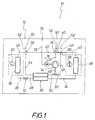
- FIG. 1 shows a diagram of an embodiment of the Device 10 for cooling and heating a vehicle.
- the facility 10 is designed as a self-sufficient flat module 12, it has a compressor 14 with a Compressor drive 16 on.
- the compressor 14 is from a carbon dioxide compressor high performance and small volume.
- the carbon dioxide compressor 14 and the compressor drive 16 are integrated in the module 12.
- the facility 10 or the module 12 also has an interior heat exchanger 18, the a blower 20 is assigned.
- the interior heat exchanger 18 is with the Compressor 14 connected by means of a first pipeline 22. In the first pipe 22, a first valve 24 and a second valve 26 are switched on.
- the interior heat exchanger 18 is connected by means of a second pipeline 28 an internal heat exchanger 30 connected.
- a Expansion device 32 turned on.
- the device 10 can also without Heat exchanger 30 can be realized or the heat exchanger 30 can also be in one other interconnection in the device 10 can be integrated.
- the internal heat exchanger 30 is in the illustrated embodiment Device 10 by means of a third pipeline 34 with an outdoor heat exchanger 36 connected to which a fan device 38 is assigned.
- the exterior heat exchanger 36 is connected by means of a fourth pipeline 40 connected to the first valve 24.
- In the fourth pipeline 40 there is a third valve 42 switched on.
- the second valve 26 is connected by means of a fifth pipeline 44 internal heat exchanger 30 connected.
- the third valve 42 is by means of a sixth Pipeline 46 connected to the internal heat exchanger 30. From the sixth Pipeline 46 branches off from a seventh pipeline 48 that connects to the compressor 14 connected.
- the heating operation of the device 10 is illustrated by the arrows 50, the first, second and third valves 24, 26 and 42 each corresponding Take a position.
- the cooling operation is illustrated by the arrows 52, the Valves 24, 26 and 42 each take a corresponding other position.
- the module 12 has an external electrical power connection 54 which is connected to the Compressor drive 16 formed by an electric motor is interconnected. This is indicated by the thin line 56.
- the electrical power connection 54 is also connected to the fan 20 and to the fan 38.
- the Compressor drive 10 can, for example, at the voltage level of 380 V three-phase current and the electrical drive of fan 20 and fan 38 may e.g. on the Voltage level 24 V DC.
- the module 12 is a self-sufficient flat module.
- Figures 2 and 3 illustrate a schematic Vehicle 58, which is an omnibus, has a roof 60 on it 58 modules corresponding to the requirements for cooling and heating energy 12, six modules 12 in the specific exemplary embodiment, are mounted.
Landscapes
- Engineering & Computer Science (AREA)
- Mechanical Engineering (AREA)
- Physics & Mathematics (AREA)
- Thermal Sciences (AREA)
- Power Engineering (AREA)
- Transportation (AREA)
- Chemical & Material Sciences (AREA)
- Chemical Kinetics & Catalysis (AREA)
- General Engineering & Computer Science (AREA)
- Air-Conditioning For Vehicles (AREA)
- Compressor (AREA)
Abstract
Description
- Figur 1
- eine Diagrammdarstellung einer Ausbildung der Kühl- und Heizeinrichtung,
- Figur 2
- einen Omnibus mit einer Anzahl auf seinem Dach montierten Einrichtungen gemäß Figur 1 in einer Seitenansicht, und
- Figur 3
- den Omnibus gemäß Figur 2 in einer Ansicht von oben.
Claims (11)
- Klimatisierungseinrichtung für ein Fahrzeug (58), mit einem Verdichter (14) mit einem Verdichterantrieb (16), einem Innenraum-Wärmeübertrager (18), einem Expansionsorgan (32), einem Außenraum-Wärmeübertrager (36), und ggf. einem internen Wärmeübertrager (30),
dadurch gekennzeichnet, daß die Einrichtung (10) als autarkes flaches Modul (12) ausgebildet ist, das in einem Kältemodus zum Kühlen und das in einem Wärmepumpenmodus zum Heizen vorgesehen ist, wobei der Verdichter (14) von einem Kohlendioxid-Verdichter hoher Leistung und kleinen Bauvolumens gebildet und mit dem Verdichterantrieb (16) in das Modul (12) integriert ist, wobei das Modul (12) einen Energieanschluß (54) nur einer einzigen Energieform zur Energieversorgung des Moduls (12) aufweist. - Einrichtung nach Anspruch 1,
dadurch gekennzeichnet, daß der Kohlendioxid-Verdichter extern leistungsgeregelt ist. - Einrichtung nach Anspruch 1 oder 2,
dadurch gekennzeichnet, daß der Kohlendioxid-Verdichter einen Durchmesser von ca. 100 bis 120 mm aufweist. - Einrichtung nach Anspruch 1,
dadurch gekennzeichnet, daß der Energieanschluß (54) des Moduls (12) ein elektrischer Energieanschluß ist, der auf einer einzigen Spannungsebene oder der auf mehreren Spannungsebenen erfolgt. - Einrichtung nach einem der Ansprüche 1 bis 4,
dadurch gekennzeichnet, daß der Verdichterantrieb (16) von einem Elektromotor gebildet ist. - Einrichtung nach Anspruch 5,
dadurch gekennzeichnet, daß der Elektromotor von einem Gleichstrommotor gebildet ist. - Einrichtung nach Anspruch 5,
dadurch gekennzeichnet, daß der Elektromotor von einem Drehstrommotor gebildet ist. - Einrichtung nach Anspruch 1,
dadurch gekennzeichnet, daß der Energieanschluß (54) des Moduls (12) ein hydraulischer oder ein pneumatischer Energieanschluß ist. - Einrichtung nach einem der Ansprüche 1 bis 8,
dadurch gekennzeichnet, daß der Verdichterantrieb (16) als Hermetikantrieb oder als Halbhermetikantrieb oder als offener Antrieb ausgebildet ist, der mit dem äußeren elektrischen Energieanschluß (54) zusammengeschaltet ist. - Einrichtung nach einem der Ansprüche 1 bis 9,
dadurch gekennzeichnet, daß das Expansionsorgan (32) von einem Kapillarrohr gebildet ist. - Einrichtung nach einem der Ansprüche 1 bis 10,
dadurch gekennzeichnet, daß das Modul (12) zur Montage auf dem Dach (60) eines Fahrzeugs (58) vorgesehen ist.
Applications Claiming Priority (2)
| Application Number | Priority Date | Filing Date | Title |
|---|---|---|---|
| DE10161254A DE10161254A1 (de) | 2001-12-13 | 2001-12-13 | Klimatisierungseinrichtung für ein Fahrzeug |
| DE10161254 | 2001-12-13 |
Publications (2)
| Publication Number | Publication Date |
|---|---|
| EP1319536A1 true EP1319536A1 (de) | 2003-06-18 |
| EP1319536B1 EP1319536B1 (de) | 2005-09-07 |
Family
ID=7709084
Family Applications (1)
| Application Number | Title | Priority Date | Filing Date |
|---|---|---|---|
| EP02023655A Revoked EP1319536B1 (de) | 2001-12-13 | 2002-10-22 | Klimatisierungseinrichtung für ein Fahrzeug |
Country Status (4)
| Country | Link |
|---|---|
| US (1) | US6708513B2 (de) |
| EP (1) | EP1319536B1 (de) |
| AT (1) | ATE303912T1 (de) |
| DE (2) | DE10161254A1 (de) |
Cited By (4)
| Publication number | Priority date | Publication date | Assignee | Title |
|---|---|---|---|---|
| WO2005032865A1 (de) * | 2003-10-02 | 2005-04-14 | Thermo King Deutschland Gmbh | Aufdachklimaanlage für ein fahrzeug, insbesondere einen omnibus |
| CN100522671C (zh) * | 2003-10-02 | 2009-08-05 | 德国皇家恒温技术设备有限公司 | 车顶空调设备 |
| WO2016108146A1 (de) * | 2014-12-29 | 2016-07-07 | PartGyx Beteiligungen AG | Flächenheizung |
| EP3628517A1 (de) * | 2018-09-25 | 2020-04-01 | MAN Truck & Bus SE | Modulare klimatisierungsvorrichtung für ein kraftfahrzeug |
Families Citing this family (27)
| Publication number | Priority date | Publication date | Assignee | Title |
|---|---|---|---|---|
| EP1422486A3 (de) * | 2002-11-25 | 2004-11-17 | Tempia Co., Ltd. | Heiz- und Kühlanlage mit kombinierter Regeneration |
| JP2004259615A (ja) * | 2003-02-26 | 2004-09-16 | Denso Corp | 燃料電池用の冷却装置 |
| US6763669B1 (en) * | 2003-05-05 | 2004-07-20 | Carrier Corporation | Modular air conditioner for a bus rooftop |
| JP2004351985A (ja) * | 2003-05-27 | 2004-12-16 | Sanden Corp | 車両用空調装置 |
| DE10337136A1 (de) * | 2003-08-11 | 2005-03-24 | Behr Gmbh & Co. Kg | Klimaanlage und Verfahren zur Regelung der Heizleistung derselben |
| DE20315237U1 (de) * | 2003-10-02 | 2005-02-17 | Thermo King Deutschland Gmbh | Aufdachklimaanlage für ein Fahrzeug, insbesondere einen Omnibus |
| DE10350177A1 (de) * | 2003-10-28 | 2005-06-16 | Webasto Ag | Dachmodul |
| DE10355397A1 (de) * | 2003-11-25 | 2005-06-30 | Behr Gmbh & Co. Kg | Kraftfahrzeug-Klimaanlage mit Standklimatisierung |
| DE102004012917B3 (de) | 2004-03-17 | 2005-08-11 | Konvekta Ag | Befestigungsvorrichtung, insbesondere für ein autarkes Klimaanlage-Modul |
| DE102005009325B4 (de) * | 2005-02-22 | 2014-08-28 | Halla Visteon Climate Control Corporation 95 | Luftbehandlungsanlage |
| DE102007004125A1 (de) * | 2007-01-26 | 2008-07-31 | Enerday Gmbh | Klimaanlage für ein Kraftfahrzeug |
| US7789176B2 (en) * | 2007-04-11 | 2010-09-07 | Tesla Motors, Inc. | Electric vehicle thermal management system |
| DE202007011617U1 (de) * | 2007-08-20 | 2009-01-08 | Thermo King Deutschland Gmbh | Anordnung zum Klimatisieren eines Fahrzeugs |
| DE102007042423A1 (de) * | 2007-09-06 | 2009-03-12 | Bayerische Motoren Werke Aktiengesellschaft | Fahrzeug mit einem Reformer |
| DE202010007146U1 (de) | 2010-05-26 | 2011-09-07 | Rehau Ag + Co. | Elektrofahrzeug |
| US8336319B2 (en) | 2010-06-04 | 2012-12-25 | Tesla Motors, Inc. | Thermal management system with dual mode coolant loops |
| US8773058B2 (en) | 2010-07-08 | 2014-07-08 | Tesla Motors, Inc. | Rotor temperature estimation and motor control torque limiting for vector-controlled AC induction motors |
| JP5595504B2 (ja) * | 2010-09-10 | 2014-09-24 | 三菱電機株式会社 | 車両用空調装置の更新方法、車両用空調装置 |
| US10427491B2 (en) | 2011-09-28 | 2019-10-01 | Tesla, Inc. | Thermal management system with heat exchanger blending valve |
| US10522845B2 (en) | 2011-09-28 | 2019-12-31 | Tesla, Inc. | Battery centric thermal management system utilizing a heat exchanger blending valve |
| WO2013071143A1 (en) * | 2011-11-11 | 2013-05-16 | Magna E-Car Systems Of America, Inc. | Simplified structure for a thermal management system for vehicle with electric drive system |
| CN105873779B (zh) * | 2013-11-25 | 2019-05-31 | 冷王公司 | 用于运输制冷单元的新鲜空气控制 |
| DE102016009460A1 (de) | 2016-08-03 | 2018-02-08 | Daimler Ag | Klimatisierungseinrichtung für ein Fahrzeug und Fahrzeug mit einer solchen Klimatisierungseinrichtung |
| DE102018123558A1 (de) | 2018-09-25 | 2020-03-26 | Man Truck & Bus Se | Modulare Klimatisierungsvorrichtung für ein Kraftfahrzeug, Kraftfahrzeug mit einer entsprechenden modularen Klimatisierungsvorrichtung sowie Verfahren zur Vorkonfiguration einer modularen Klimatisierungsvorrichtung |
| US11642936B2 (en) | 2021-09-30 | 2023-05-09 | Midea Group Co., Ltd. | Recreational vehicle air conditioning system with load sharing |
| US11407280B1 (en) | 2022-02-10 | 2022-08-09 | Rancho Del I.P. | Ultra-low-cost coolant heating apparatus for electric vehicle applications |
| US11766920B2 (en) | 2022-02-10 | 2023-09-26 | Rancho Del I.P. | Selective efficiency traction inverters and chargers as heat sources for thermal conditioning of electric vehicles |
Citations (5)
| Publication number | Priority date | Publication date | Assignee | Title |
|---|---|---|---|---|
| US4098093A (en) * | 1976-12-06 | 1978-07-04 | Vapor Corporation | Unitary cab air cooling system for large off road vehicles |
| EP0214553A2 (de) * | 1985-08-30 | 1987-03-18 | Konvekta Aktiengesellschaft | Klimaanlage für ein Kraftfahrzeug |
| EP0827855A2 (de) * | 1996-09-10 | 1998-03-11 | Ernst Gaus | Klimagerät für Fahrzeugkabinen |
| DE19806654A1 (de) * | 1998-02-18 | 1999-08-19 | Obrist Engineering Gmbh | Klimaanlage für Fahrzeuge |
| US6230506B1 (en) * | 1998-08-24 | 2001-05-15 | Denso Corporation | Heat pump cycle system |
Family Cites Families (15)
| Publication number | Priority date | Publication date | Assignee | Title |
|---|---|---|---|---|
| US4641502A (en) * | 1985-01-09 | 1987-02-10 | The Duo-Therm Corporation | Roof mount air conditioner |
| US4732011A (en) * | 1985-05-17 | 1988-03-22 | Diesel Kiki Co., Ltd. | Air conditioner for vehicles |
| KR0144562B1 (ko) * | 1989-09-12 | 1998-08-17 | 크리스트, 퀼 | 진공개폐기용 CuCr-재료의 제조방법 및 그 접점재료 |
| US5184474A (en) * | 1991-11-15 | 1993-02-09 | Suetrak Air Conditioning Sales Corp. | Roof-mounted air conditioning system with built-in compressor |
| DE19903425A1 (de) * | 1999-01-29 | 2000-08-10 | Bosch Gmbh Robert | Klimaanlage für ein Kraftfahrzeug |
| DE19524670A1 (de) * | 1995-07-06 | 1997-01-09 | Thermal Werke Beteiligungen Gm | Kühlanordnung für Nutzfahrzeuge, insbesondere Omnibusse |
| JP3665346B2 (ja) * | 1996-01-26 | 2005-06-29 | コンヴェクタ アクチェンゲゼルシャフト | 圧縮冷却装置 |
| DE19813673B4 (de) * | 1998-03-27 | 2004-01-29 | Daimlerchrysler Ag | Verfahren und Vorrichtung zum Heizen und Kühlen eines Nutzraumes eines Kraftfahrzeuges |
| DE19925827C1 (de) * | 1998-07-01 | 2001-01-18 | Konvekta Ag | Anlage mit einer Wärmepumpe und einem Speicher |
| DE19832479A1 (de) * | 1998-07-20 | 2000-01-27 | Behr Gmbh & Co | Mit CO¶2¶ betreibbare Klimaanlage |
| JP2000233638A (ja) * | 1999-02-16 | 2000-08-29 | Nissan Motor Co Ltd | 車両用空調装置の安全装置 |
| JP2001207960A (ja) * | 2000-01-25 | 2001-08-03 | Toyota Autom Loom Works Ltd | 空気調和装置 |
| DE10006513B4 (de) * | 2000-02-15 | 2014-12-24 | Behr Gmbh & Co. Kg | Klimaanlage für ein Kraftfahrzeug mit Wärmepumpen- und/oder Reheat-Betriebsart |
| JP2002195677A (ja) * | 2000-10-20 | 2002-07-10 | Denso Corp | ヒートポンプサイクル |
| JP4639541B2 (ja) * | 2001-03-01 | 2011-02-23 | 株式会社デンソー | エジェクタを用いたサイクル |
-
2001
- 2001-12-13 DE DE10161254A patent/DE10161254A1/de not_active Withdrawn
-
2002
- 2002-10-22 DE DE50204167T patent/DE50204167D1/de not_active Revoked
- 2002-10-22 AT AT02023655T patent/ATE303912T1/de not_active IP Right Cessation
- 2002-10-22 EP EP02023655A patent/EP1319536B1/de not_active Revoked
- 2002-12-05 US US10/310,450 patent/US6708513B2/en not_active Expired - Fee Related
Patent Citations (5)
| Publication number | Priority date | Publication date | Assignee | Title |
|---|---|---|---|---|
| US4098093A (en) * | 1976-12-06 | 1978-07-04 | Vapor Corporation | Unitary cab air cooling system for large off road vehicles |
| EP0214553A2 (de) * | 1985-08-30 | 1987-03-18 | Konvekta Aktiengesellschaft | Klimaanlage für ein Kraftfahrzeug |
| EP0827855A2 (de) * | 1996-09-10 | 1998-03-11 | Ernst Gaus | Klimagerät für Fahrzeugkabinen |
| DE19806654A1 (de) * | 1998-02-18 | 1999-08-19 | Obrist Engineering Gmbh | Klimaanlage für Fahrzeuge |
| US6230506B1 (en) * | 1998-08-24 | 2001-05-15 | Denso Corporation | Heat pump cycle system |
Cited By (4)
| Publication number | Priority date | Publication date | Assignee | Title |
|---|---|---|---|---|
| WO2005032865A1 (de) * | 2003-10-02 | 2005-04-14 | Thermo King Deutschland Gmbh | Aufdachklimaanlage für ein fahrzeug, insbesondere einen omnibus |
| CN100522671C (zh) * | 2003-10-02 | 2009-08-05 | 德国皇家恒温技术设备有限公司 | 车顶空调设备 |
| WO2016108146A1 (de) * | 2014-12-29 | 2016-07-07 | PartGyx Beteiligungen AG | Flächenheizung |
| EP3628517A1 (de) * | 2018-09-25 | 2020-04-01 | MAN Truck & Bus SE | Modulare klimatisierungsvorrichtung für ein kraftfahrzeug |
Also Published As
| Publication number | Publication date |
|---|---|
| DE50204167D1 (de) | 2005-10-13 |
| US20030110787A1 (en) | 2003-06-19 |
| US6708513B2 (en) | 2004-03-23 |
| ATE303912T1 (de) | 2005-09-15 |
| EP1319536B1 (de) | 2005-09-07 |
| DE10161254A1 (de) | 2003-07-03 |
Similar Documents
| Publication | Publication Date | Title |
|---|---|---|
| EP1319536B1 (de) | Klimatisierungseinrichtung für ein Fahrzeug | |
| DE102009028522B4 (de) | Kompakte Klimaanlage für ein Kraftfahrzeug | |
| DE60028129T2 (de) | Fahrzeugklimaanlage | |
| DE19850829C1 (de) | Kühl-Heiz-Kreis für ein Fahrzeug | |
| DE102018118118A1 (de) | Klimatisierungssystem eines Kraftfahrzeugs und Verfahren zum Betreiben des Klimatisierungssystems | |
| EP2608973B1 (de) | Heiz-/kühleinrichtung und heiz-/kühl-modul für eine heiz-/kühleinrichtung | |
| DE4209188C2 (de) | Anordnung zur Klimatisierung von Räumen, insbesondere der Fahrgastzelle von Kraftfahrzeugen | |
| DE102010051976B4 (de) | Klimaanlage für ein Kraftfahrzeug | |
| DE102013227034A1 (de) | Thermomanagement für ein Elektro- oder Hybridfahrzeug sowie ein Verfahren zur Konditionierung des Innenraums eines solchen Kraftfahrzeugs | |
| DE102018104410A1 (de) | Klimatisierungssystem eines Kraftfahrzeugs und Verfahren zum Betreiben des Klimatisierungssystems | |
| DE102011052752A1 (de) | Modulare Fahrzeugklimaanlage mit Wärmepumpenfunktionalität | |
| DE102015218824A1 (de) | Wärmepumpensystem und Verfahren zum Betrieb eines solchen | |
| DE102012108886A1 (de) | Wärmeübertrageranordnung und Klimatisierungssystem eines Kraftfahrzeuges | |
| DE102009060860A1 (de) | Klimatisierungssystem für ein Fahrzeug sowie Verfahren zum Temperieren | |
| DE102009043316A1 (de) | Verfahren zur Steuerung der Innenraumtemperatur eines elektrisch betriebenen Fahrzeugs und Klimaanlagensystem | |
| DE102004002715A1 (de) | Klimaanlage für ein Kraftfahrzeug | |
| DE19524660C1 (de) | Klimatisierungsanordnung für Nutzfahrzeuge, insbesondere Omnibusse | |
| DE102016203045A1 (de) | Temperiereinrichtung zum Temperieren eines Innenraums eines Fahrzeugs sowie Verfahren zum Betreiben einer solchen Temperiereinrichtung | |
| DE112021004718T5 (de) | Dampfeinspritzmodul und wärmepumpensystem mit diesem modul | |
| DE102020133101A1 (de) | Thermisches System eines Kraftfahrzeugs und Verfahren zum Betreiben des thermischen Systems | |
| WO2014166596A1 (de) | Fahrzeugklimatisierungseinrichtung | |
| EP1347885A1 (de) | Anordnung und verfahren zum kühlen beziehungsweise heizen | |
| EP1667862A1 (de) | Aufdachklimaanlage für ein fahrzeug, insbesondere einen omnibus | |
| EP3628517B2 (de) | Modulare klimatisierungsvorrichtung für ein kraftfahrzeug | |
| WO2023012315A1 (de) | Kältemittelkreislaufvorrichtung mit mehreren inneren kältemittelkreisläufen |
Legal Events
| Date | Code | Title | Description |
|---|---|---|---|
| PUAI | Public reference made under article 153(3) epc to a published international application that has entered the european phase |
Free format text: ORIGINAL CODE: 0009012 |
|
| AK | Designated contracting states |
Designated state(s): AT BE BG CH CY CZ DE DK EE ES FI FR GB GR IE IT LI LU MC NL PT SE SK TR |
|
| AX | Request for extension of the european patent |
Extension state: AL LT LV MK RO SI |
|
| RAP1 | Party data changed (applicant data changed or rights of an application transferred) |
Owner name: KONVEKTA AG |
|
| 17P | Request for examination filed |
Effective date: 20031114 |
|
| 17Q | First examination report despatched |
Effective date: 20040127 |
|
| AKX | Designation fees paid |
Designated state(s): AT BE BG CH CY CZ DE DK EE ES FI FR GB GR IE IT LI LU MC NL PT SE SK TR |
|
| GRAP | Despatch of communication of intention to grant a patent |
Free format text: ORIGINAL CODE: EPIDOSNIGR1 |
|
| GRAS | Grant fee paid |
Free format text: ORIGINAL CODE: EPIDOSNIGR3 |
|
| GRAA | (expected) grant |
Free format text: ORIGINAL CODE: 0009210 |
|
| AK | Designated contracting states |
Kind code of ref document: B1 Designated state(s): AT BE BG CH CY CZ DE DK EE ES FI FR GB GR IE IT LI LU MC NL PT SE SK TR |
|
| PG25 | Lapsed in a contracting state [announced via postgrant information from national office to epo] |
Ref country code: IT Free format text: LAPSE BECAUSE OF FAILURE TO SUBMIT A TRANSLATION OF THE DESCRIPTION OR TO PAY THE FEE WITHIN THE PRESCRIBED TIME-LIMIT;WARNING: LAPSES OF ITALIAN PATENTS WITH EFFECTIVE DATE BEFORE 2007 MAY HAVE OCCURRED AT ANY TIME BEFORE 2007. THE CORRECT EFFECTIVE DATE MAY BE DIFFERENT FROM THE ONE RECORDED. Effective date: 20050907 Ref country code: CZ Free format text: LAPSE BECAUSE OF FAILURE TO SUBMIT A TRANSLATION OF THE DESCRIPTION OR TO PAY THE FEE WITHIN THE PRESCRIBED TIME-LIMIT Effective date: 20050907 Ref country code: NL Free format text: LAPSE BECAUSE OF FAILURE TO SUBMIT A TRANSLATION OF THE DESCRIPTION OR TO PAY THE FEE WITHIN THE PRESCRIBED TIME-LIMIT Effective date: 20050907 Ref country code: EE Free format text: LAPSE BECAUSE OF FAILURE TO SUBMIT A TRANSLATION OF THE DESCRIPTION OR TO PAY THE FEE WITHIN THE PRESCRIBED TIME-LIMIT Effective date: 20050907 Ref country code: FI Free format text: LAPSE BECAUSE OF FAILURE TO SUBMIT A TRANSLATION OF THE DESCRIPTION OR TO PAY THE FEE WITHIN THE PRESCRIBED TIME-LIMIT Effective date: 20050907 Ref country code: IE Free format text: LAPSE BECAUSE OF FAILURE TO SUBMIT A TRANSLATION OF THE DESCRIPTION OR TO PAY THE FEE WITHIN THE PRESCRIBED TIME-LIMIT Effective date: 20050907 Ref country code: ES Free format text: LAPSE BECAUSE OF FAILURE TO SUBMIT A TRANSLATION OF THE DESCRIPTION OR TO PAY THE FEE WITHIN THE PRESCRIBED TIME-LIMIT Effective date: 20050907 Ref country code: TR Free format text: LAPSE BECAUSE OF FAILURE TO SUBMIT A TRANSLATION OF THE DESCRIPTION OR TO PAY THE FEE WITHIN THE PRESCRIBED TIME-LIMIT Effective date: 20050907 Ref country code: GB Free format text: LAPSE BECAUSE OF FAILURE TO SUBMIT A TRANSLATION OF THE DESCRIPTION OR TO PAY THE FEE WITHIN THE PRESCRIBED TIME-LIMIT Effective date: 20050907 Ref country code: SK Free format text: LAPSE BECAUSE OF FAILURE TO SUBMIT A TRANSLATION OF THE DESCRIPTION OR TO PAY THE FEE WITHIN THE PRESCRIBED TIME-LIMIT Effective date: 20050907 |
|
| REG | Reference to a national code |
Ref country code: GB Ref legal event code: FG4D Free format text: NOT ENGLISH |
|
| REG | Reference to a national code |
Ref country code: CH Ref legal event code: EP |
|
| REG | Reference to a national code |
Ref country code: IE Ref legal event code: FG4D Free format text: LANGUAGE OF EP DOCUMENT: GERMAN |
|
| REF | Corresponds to: |
Ref document number: 50204167 Country of ref document: DE Date of ref document: 20051013 Kind code of ref document: P |
|
| PG25 | Lapsed in a contracting state [announced via postgrant information from national office to epo] |
Ref country code: AT Free format text: LAPSE BECAUSE OF NON-PAYMENT OF DUE FEES Effective date: 20051022 Ref country code: CY Free format text: LAPSE BECAUSE OF FAILURE TO SUBMIT A TRANSLATION OF THE DESCRIPTION OR TO PAY THE FEE WITHIN THE PRESCRIBED TIME-LIMIT Effective date: 20051022 |
|
| PG25 | Lapsed in a contracting state [announced via postgrant information from national office to epo] |
Ref country code: BE Free format text: LAPSE BECAUSE OF NON-PAYMENT OF DUE FEES Effective date: 20051031 Ref country code: MC Free format text: LAPSE BECAUSE OF NON-PAYMENT OF DUE FEES Effective date: 20051031 |
|
| PG25 | Lapsed in a contracting state [announced via postgrant information from national office to epo] |
Ref country code: LU Free format text: LAPSE BECAUSE OF NON-PAYMENT OF DUE FEES Effective date: 20051107 |
|
| PG25 | Lapsed in a contracting state [announced via postgrant information from national office to epo] |
Ref country code: GR Free format text: LAPSE BECAUSE OF FAILURE TO SUBMIT A TRANSLATION OF THE DESCRIPTION OR TO PAY THE FEE WITHIN THE PRESCRIBED TIME-LIMIT Effective date: 20051207 Ref country code: BG Free format text: LAPSE BECAUSE OF FAILURE TO SUBMIT A TRANSLATION OF THE DESCRIPTION OR TO PAY THE FEE WITHIN THE PRESCRIBED TIME-LIMIT Effective date: 20051207 Ref country code: DK Free format text: LAPSE BECAUSE OF FAILURE TO SUBMIT A TRANSLATION OF THE DESCRIPTION OR TO PAY THE FEE WITHIN THE PRESCRIBED TIME-LIMIT Effective date: 20051207 Ref country code: SE Free format text: LAPSE BECAUSE OF FAILURE TO SUBMIT A TRANSLATION OF THE DESCRIPTION OR TO PAY THE FEE WITHIN THE PRESCRIBED TIME-LIMIT Effective date: 20051207 |
|
| PG25 | Lapsed in a contracting state [announced via postgrant information from national office to epo] |
Ref country code: PT Free format text: LAPSE BECAUSE OF FAILURE TO SUBMIT A TRANSLATION OF THE DESCRIPTION OR TO PAY THE FEE WITHIN THE PRESCRIBED TIME-LIMIT Effective date: 20060207 |
|
| NLV1 | Nl: lapsed or annulled due to failure to fulfill the requirements of art. 29p and 29m of the patents act | ||
| GBV | Gb: ep patent (uk) treated as always having been void in accordance with gb section 77(7)/1977 [no translation filed] |
Effective date: 20050907 |
|
| REG | Reference to a national code |
Ref country code: IE Ref legal event code: FD4D |
|
| ET | Fr: translation filed | ||
| PLBI | Opposition filed |
Free format text: ORIGINAL CODE: 0009260 |
|
| PLAX | Notice of opposition and request to file observation + time limit sent |
Free format text: ORIGINAL CODE: EPIDOSNOBS2 |
|
| 26 | Opposition filed |
Opponent name: BEHR GMBH & CO. KG Effective date: 20060607 |
|
| PG25 | Lapsed in a contracting state [announced via postgrant information from national office to epo] |
Ref country code: CH Free format text: LAPSE BECAUSE OF NON-PAYMENT OF DUE FEES Effective date: 20061031 Ref country code: LI Free format text: LAPSE BECAUSE OF NON-PAYMENT OF DUE FEES Effective date: 20061031 |
|
| PLAF | Information modified related to communication of a notice of opposition and request to file observations + time limit |
Free format text: ORIGINAL CODE: EPIDOSCOBS2 |
|
| PLBB | Reply of patent proprietor to notice(s) of opposition received |
Free format text: ORIGINAL CODE: EPIDOSNOBS3 |
|
| REG | Reference to a national code |
Ref country code: CH Ref legal event code: PL |
|
| BERE | Be: lapsed |
Owner name: KONVEKTA A.G. Effective date: 20051031 |
|
| PLAB | Opposition data, opponent's data or that of the opponent's representative modified |
Free format text: ORIGINAL CODE: 0009299OPPO |
|
| PGFP | Annual fee paid to national office [announced via postgrant information from national office to epo] |
Ref country code: DE Payment date: 20080723 Year of fee payment: 7 |
|
| PGFP | Annual fee paid to national office [announced via postgrant information from national office to epo] |
Ref country code: FR Payment date: 20081021 Year of fee payment: 7 |
|
| PLBP | Opposition withdrawn |
Free format text: ORIGINAL CODE: 0009264 |
|
| RDAF | Communication despatched that patent is revoked |
Free format text: ORIGINAL CODE: EPIDOSNREV1 |
|
| RDAG | Patent revoked |
Free format text: ORIGINAL CODE: 0009271 |
|
| STAA | Information on the status of an ep patent application or granted ep patent |
Free format text: STATUS: PATENT REVOKED |
|
| 27W | Patent revoked |
Effective date: 20090930 |