EP1320697B1 - Verfahren und einrichtung zum betrieb einer kupplung - Google Patents
Verfahren und einrichtung zum betrieb einer kupplung Download PDFInfo
- Publication number
- EP1320697B1 EP1320697B1 EP01974008A EP01974008A EP1320697B1 EP 1320697 B1 EP1320697 B1 EP 1320697B1 EP 01974008 A EP01974008 A EP 01974008A EP 01974008 A EP01974008 A EP 01974008A EP 1320697 B1 EP1320697 B1 EP 1320697B1
- Authority
- EP
- European Patent Office
- Prior art keywords
- clutch
- temperature
- torque
- pressing force
- pressure
- Prior art date
- Legal status (The legal status is an assumption and is not a legal conclusion. Google has not performed a legal analysis and makes no representation as to the accuracy of the status listed.)
- Expired - Lifetime
Links
- 238000000034 method Methods 0.000 title claims abstract description 17
- 238000002485 combustion reaction Methods 0.000 claims abstract description 22
- 230000001105 regulatory effect Effects 0.000 claims abstract description 11
- 238000001816 cooling Methods 0.000 claims description 3
- 230000001419 dependent effect Effects 0.000 claims description 3
- 230000001050 lubricating effect Effects 0.000 claims 2
- 230000006835 compression Effects 0.000 abstract 4
- 238000007906 compression Methods 0.000 abstract 4
- 230000005540 biological transmission Effects 0.000 description 23
- 229910000831 Steel Inorganic materials 0.000 description 14
- 230000008878 coupling Effects 0.000 description 14
- 238000010168 coupling process Methods 0.000 description 14
- 238000005859 coupling reaction Methods 0.000 description 14
- 239000010959 steel Substances 0.000 description 14
- 239000003921 oil Substances 0.000 description 10
- 230000008569 process Effects 0.000 description 5
- 239000010720 hydraulic oil Substances 0.000 description 4
- 239000010687 lubricating oil Substances 0.000 description 4
- 230000004044 response Effects 0.000 description 4
- 230000001276 controlling effect Effects 0.000 description 3
- 230000001681 protective effect Effects 0.000 description 3
- 238000012546 transfer Methods 0.000 description 2
- 238000001514 detection method Methods 0.000 description 1
- 238000010586 diagram Methods 0.000 description 1
- 238000001914 filtration Methods 0.000 description 1
- 239000012530 fluid Substances 0.000 description 1
- 238000010438 heat treatment Methods 0.000 description 1
- 238000005461 lubrication Methods 0.000 description 1
- 239000000463 material Substances 0.000 description 1
- 230000004048 modification Effects 0.000 description 1
- 238000012986 modification Methods 0.000 description 1
- 238000012544 monitoring process Methods 0.000 description 1
- 230000035939 shock Effects 0.000 description 1
- 230000007704 transition Effects 0.000 description 1
- 238000013519 translation Methods 0.000 description 1
Images




Classifications
-
- F—MECHANICAL ENGINEERING; LIGHTING; HEATING; WEAPONS; BLASTING
- F16—ENGINEERING ELEMENTS AND UNITS; GENERAL MEASURES FOR PRODUCING AND MAINTAINING EFFECTIVE FUNCTIONING OF MACHINES OR INSTALLATIONS; THERMAL INSULATION IN GENERAL
- F16D—COUPLINGS FOR TRANSMITTING ROTATION; CLUTCHES; BRAKES
- F16D48/00—External control of clutches
- F16D48/06—Control by electric or electronic means, e.g. of fluid pressure
-
- F—MECHANICAL ENGINEERING; LIGHTING; HEATING; WEAPONS; BLASTING
- F16—ENGINEERING ELEMENTS AND UNITS; GENERAL MEASURES FOR PRODUCING AND MAINTAINING EFFECTIVE FUNCTIONING OF MACHINES OR INSTALLATIONS; THERMAL INSULATION IN GENERAL
- F16D—COUPLINGS FOR TRANSMITTING ROTATION; CLUTCHES; BRAKES
- F16D48/00—External control of clutches
- F16D48/06—Control by electric or electronic means, e.g. of fluid pressure
- F16D48/066—Control of fluid pressure, e.g. using an accumulator
-
- B—PERFORMING OPERATIONS; TRANSPORTING
- B60—VEHICLES IN GENERAL
- B60W—CONJOINT CONTROL OF VEHICLE SUB-UNITS OF DIFFERENT TYPE OR DIFFERENT FUNCTION; CONTROL SYSTEMS SPECIALLY ADAPTED FOR HYBRID VEHICLES; ROAD VEHICLE DRIVE CONTROL SYSTEMS FOR PURPOSES NOT RELATED TO THE CONTROL OF A PARTICULAR SUB-UNIT
- B60W2510/00—Input parameters relating to a particular sub-units
- B60W2510/02—Clutches
- B60W2510/0241—Clutch slip, i.e. difference between input and output speeds
-
- B—PERFORMING OPERATIONS; TRANSPORTING
- B60—VEHICLES IN GENERAL
- B60W—CONJOINT CONTROL OF VEHICLE SUB-UNITS OF DIFFERENT TYPE OR DIFFERENT FUNCTION; CONTROL SYSTEMS SPECIALLY ADAPTED FOR HYBRID VEHICLES; ROAD VEHICLE DRIVE CONTROL SYSTEMS FOR PURPOSES NOT RELATED TO THE CONTROL OF A PARTICULAR SUB-UNIT
- B60W2510/00—Input parameters relating to a particular sub-units
- B60W2510/02—Clutches
- B60W2510/0291—Clutch temperature
-
- B—PERFORMING OPERATIONS; TRANSPORTING
- B60—VEHICLES IN GENERAL
- B60W—CONJOINT CONTROL OF VEHICLE SUB-UNITS OF DIFFERENT TYPE OR DIFFERENT FUNCTION; CONTROL SYSTEMS SPECIALLY ADAPTED FOR HYBRID VEHICLES; ROAD VEHICLE DRIVE CONTROL SYSTEMS FOR PURPOSES NOT RELATED TO THE CONTROL OF A PARTICULAR SUB-UNIT
- B60W2510/00—Input parameters relating to a particular sub-units
- B60W2510/06—Combustion engines, Gas turbines
- B60W2510/0657—Engine torque
-
- B—PERFORMING OPERATIONS; TRANSPORTING
- B60—VEHICLES IN GENERAL
- B60W—CONJOINT CONTROL OF VEHICLE SUB-UNITS OF DIFFERENT TYPE OR DIFFERENT FUNCTION; CONTROL SYSTEMS SPECIALLY ADAPTED FOR HYBRID VEHICLES; ROAD VEHICLE DRIVE CONTROL SYSTEMS FOR PURPOSES NOT RELATED TO THE CONTROL OF A PARTICULAR SUB-UNIT
- B60W2710/00—Output or target parameters relating to a particular sub-units
- B60W2710/02—Clutches
- B60W2710/025—Clutch slip, i.e. difference between input and output speeds
-
- F—MECHANICAL ENGINEERING; LIGHTING; HEATING; WEAPONS; BLASTING
- F16—ENGINEERING ELEMENTS AND UNITS; GENERAL MEASURES FOR PRODUCING AND MAINTAINING EFFECTIVE FUNCTIONING OF MACHINES OR INSTALLATIONS; THERMAL INSULATION IN GENERAL
- F16D—COUPLINGS FOR TRANSMITTING ROTATION; CLUTCHES; BRAKES
- F16D2500/00—External control of clutches by electric or electronic means
- F16D2500/30—Signal inputs
- F16D2500/304—Signal inputs from the clutch
- F16D2500/30402—Clutch friction coefficient
-
- F—MECHANICAL ENGINEERING; LIGHTING; HEATING; WEAPONS; BLASTING
- F16—ENGINEERING ELEMENTS AND UNITS; GENERAL MEASURES FOR PRODUCING AND MAINTAINING EFFECTIVE FUNCTIONING OF MACHINES OR INSTALLATIONS; THERMAL INSULATION IN GENERAL
- F16D—COUPLINGS FOR TRANSMITTING ROTATION; CLUTCHES; BRAKES
- F16D2500/00—External control of clutches by electric or electronic means
- F16D2500/30—Signal inputs
- F16D2500/304—Signal inputs from the clutch
- F16D2500/30404—Clutch temperature
-
- F—MECHANICAL ENGINEERING; LIGHTING; HEATING; WEAPONS; BLASTING
- F16—ENGINEERING ELEMENTS AND UNITS; GENERAL MEASURES FOR PRODUCING AND MAINTAINING EFFECTIVE FUNCTIONING OF MACHINES OR INSTALLATIONS; THERMAL INSULATION IN GENERAL
- F16D—COUPLINGS FOR TRANSMITTING ROTATION; CLUTCHES; BRAKES
- F16D2500/00—External control of clutches by electric or electronic means
- F16D2500/30—Signal inputs
- F16D2500/304—Signal inputs from the clutch
- F16D2500/30406—Clutch slip
-
- F—MECHANICAL ENGINEERING; LIGHTING; HEATING; WEAPONS; BLASTING
- F16—ENGINEERING ELEMENTS AND UNITS; GENERAL MEASURES FOR PRODUCING AND MAINTAINING EFFECTIVE FUNCTIONING OF MACHINES OR INSTALLATIONS; THERMAL INSULATION IN GENERAL
- F16D—COUPLINGS FOR TRANSMITTING ROTATION; CLUTCHES; BRAKES
- F16D2500/00—External control of clutches by electric or electronic means
- F16D2500/30—Signal inputs
- F16D2500/304—Signal inputs from the clutch
- F16D2500/3042—Signal inputs from the clutch from the output shaft
- F16D2500/30421—Torque of the output shaft
-
- F—MECHANICAL ENGINEERING; LIGHTING; HEATING; WEAPONS; BLASTING
- F16—ENGINEERING ELEMENTS AND UNITS; GENERAL MEASURES FOR PRODUCING AND MAINTAINING EFFECTIVE FUNCTIONING OF MACHINES OR INSTALLATIONS; THERMAL INSULATION IN GENERAL
- F16D—COUPLINGS FOR TRANSMITTING ROTATION; CLUTCHES; BRAKES
- F16D2500/00—External control of clutches by electric or electronic means
- F16D2500/30—Signal inputs
- F16D2500/305—Signal inputs from the clutch cooling
- F16D2500/3055—Cooling oil properties
- F16D2500/3056—Cooling oil temperature
-
- F—MECHANICAL ENGINEERING; LIGHTING; HEATING; WEAPONS; BLASTING
- F16—ENGINEERING ELEMENTS AND UNITS; GENERAL MEASURES FOR PRODUCING AND MAINTAINING EFFECTIVE FUNCTIONING OF MACHINES OR INSTALLATIONS; THERMAL INSULATION IN GENERAL
- F16D—COUPLINGS FOR TRANSMITTING ROTATION; CLUTCHES; BRAKES
- F16D2500/00—External control of clutches by electric or electronic means
- F16D2500/70—Details about the implementation of the control system
- F16D2500/704—Output parameters from the control unit; Target parameters to be controlled
- F16D2500/70402—Actuator parameters
- F16D2500/70404—Force
-
- F—MECHANICAL ENGINEERING; LIGHTING; HEATING; WEAPONS; BLASTING
- F16—ENGINEERING ELEMENTS AND UNITS; GENERAL MEASURES FOR PRODUCING AND MAINTAINING EFFECTIVE FUNCTIONING OF MACHINES OR INSTALLATIONS; THERMAL INSULATION IN GENERAL
- F16D—COUPLINGS FOR TRANSMITTING ROTATION; CLUTCHES; BRAKES
- F16D2500/00—External control of clutches by electric or electronic means
- F16D2500/70—Details about the implementation of the control system
- F16D2500/704—Output parameters from the control unit; Target parameters to be controlled
- F16D2500/70402—Actuator parameters
- F16D2500/70406—Pressure
-
- F—MECHANICAL ENGINEERING; LIGHTING; HEATING; WEAPONS; BLASTING
- F16—ENGINEERING ELEMENTS AND UNITS; GENERAL MEASURES FOR PRODUCING AND MAINTAINING EFFECTIVE FUNCTIONING OF MACHINES OR INSTALLATIONS; THERMAL INSULATION IN GENERAL
- F16D—COUPLINGS FOR TRANSMITTING ROTATION; CLUTCHES; BRAKES
- F16D2500/00—External control of clutches by electric or electronic means
- F16D2500/70—Details about the implementation of the control system
- F16D2500/704—Output parameters from the control unit; Target parameters to be controlled
- F16D2500/70422—Clutch parameters
- F16D2500/70438—From the output shaft
- F16D2500/7044—Output shaft torque
-
- F—MECHANICAL ENGINEERING; LIGHTING; HEATING; WEAPONS; BLASTING
- F16—ENGINEERING ELEMENTS AND UNITS; GENERAL MEASURES FOR PRODUCING AND MAINTAINING EFFECTIVE FUNCTIONING OF MACHINES OR INSTALLATIONS; THERMAL INSULATION IN GENERAL
- F16D—COUPLINGS FOR TRANSMITTING ROTATION; CLUTCHES; BRAKES
- F16D2500/00—External control of clutches by electric or electronic means
- F16D2500/70—Details about the implementation of the control system
- F16D2500/704—Output parameters from the control unit; Target parameters to be controlled
- F16D2500/70452—Engine parameters
- F16D2500/70458—Engine torque
-
- F—MECHANICAL ENGINEERING; LIGHTING; HEATING; WEAPONS; BLASTING
- F16—ENGINEERING ELEMENTS AND UNITS; GENERAL MEASURES FOR PRODUCING AND MAINTAINING EFFECTIVE FUNCTIONING OF MACHINES OR INSTALLATIONS; THERMAL INSULATION IN GENERAL
- F16D—COUPLINGS FOR TRANSMITTING ROTATION; CLUTCHES; BRAKES
- F16D2500/00—External control of clutches by electric or electronic means
- F16D2500/70—Details about the implementation of the control system
- F16D2500/704—Output parameters from the control unit; Target parameters to be controlled
- F16D2500/70464—Transmission parameters
- F16D2500/70476—Output shaft
- F16D2500/7048—Output shaft torque
-
- F—MECHANICAL ENGINEERING; LIGHTING; HEATING; WEAPONS; BLASTING
- F16—ENGINEERING ELEMENTS AND UNITS; GENERAL MEASURES FOR PRODUCING AND MAINTAINING EFFECTIVE FUNCTIONING OF MACHINES OR INSTALLATIONS; THERMAL INSULATION IN GENERAL
- F16H—GEARING
- F16H59/00—Control inputs to control units of change-speed- or reversing-gearings for conveying rotary motion
- F16H59/68—Inputs being a function of gearing status
- F16H59/72—Inputs being a function of gearing status dependent on oil characteristics, e.g. temperature, viscosity
- F16H2059/725—Sensing or calculating temperature of oil in friction devices, e.g. wet clutches, to prevent overheating of friction linings
-
- F—MECHANICAL ENGINEERING; LIGHTING; HEATING; WEAPONS; BLASTING
- F16—ENGINEERING ELEMENTS AND UNITS; GENERAL MEASURES FOR PRODUCING AND MAINTAINING EFFECTIVE FUNCTIONING OF MACHINES OR INSTALLATIONS; THERMAL INSULATION IN GENERAL
- F16H—GEARING
- F16H59/00—Control inputs to control units of change-speed- or reversing-gearings for conveying rotary motion
- F16H59/68—Inputs being a function of gearing status
- F16H59/72—Inputs being a function of gearing status dependent on oil characteristics, e.g. temperature, viscosity
-
- F—MECHANICAL ENGINEERING; LIGHTING; HEATING; WEAPONS; BLASTING
- F16—ENGINEERING ELEMENTS AND UNITS; GENERAL MEASURES FOR PRODUCING AND MAINTAINING EFFECTIVE FUNCTIONING OF MACHINES OR INSTALLATIONS; THERMAL INSULATION IN GENERAL
- F16H—GEARING
- F16H61/00—Control functions within control units of change-speed- or reversing-gearings for conveying rotary motion ; Control of exclusively fluid gearing, friction gearing, gearings with endless flexible members or other particular types of gearing
- F16H61/14—Control of torque converter lock-up clutches
- F16H61/143—Control of torque converter lock-up clutches using electric control means
Definitions
- the invention relates to a method and a device for operating a clutch between an internal combustion engine and at least one drive wheel of a vehicle, wherein a moment between the engine and the drive wheel is transmitted by compressing the clutch with a contact pressure or a contact pressure.
- US 5,403,250 discloses a method of operating a clutch between an internal combustion engine and a drive wheel of a vehicle in which a moment between the engine and the drive wheel is transmitted by compressing the clutch and the clutch pressure in response to a measured temperature of the clutch controlled or regulated. Depending on the measured temperature of the clutch and on the setpoint value for the clutch slip, a value for the friction coefficient of the clutch is read from a diagram.
- a control device for actuating a friction clutch in a motor vehicle in which a clutch actuator is actuated in response to a throttle position.
- the control device is connected to a temperature sensor comprising a wax material which expands upon heating of the clutch and actuates a switch electrically connected to the control device.
- DE 198 51 341 A1 discloses a method for differential speed control of a clutch, in which a target speed difference between the input and output side of the clutch as a reference variable and the current speed variable is used as a controlled variable for controlling the clutch slip. From the transmission oil temperature in conjunction with a mathematical-physical model of the heat input in the slip operation of the frictional connection a temperature monitoring of the frictional connection is carried out in order to avoid damage to the clutch linings.
- This object is achieved by a method and a device for operating a clutch between an internal combustion engine and at least one drive wheel of a vehicle, wherein a moment between the internal combustion engine and the drive wheel is transmitted by compressing the clutch with a contact pressure or a contact pressure, according to claim 1 or according to claim 6 solved by the contact pressure or the contact pressure in dependence on a temperature a friction surface of the clutch is controlled, wherein the temperature of the friction surface of the clutch is calculated by means of a temperature model, in which a mathematical relationship between the calculated temperature of the friction surface of the clutch and other parameters, in particular a detected temperature of oil for lubrication or cooling the clutch is implemented.
- the torque to be transmitted between the engine and the drive wheel is increased by a predetermined value when the temperature of a friction surface of the clutch is above a threshold.
- the contact pressure or the contact pressure in response to a clutch slip in the clutch when transmitting the torque between the engine and the drive wheel and a target clutch slip is controlled, especially if the temperature of a friction surface of the clutch is less than or equal to the threshold ,
- the contact pressure or the contact pressure as a function of the difference between the clutch slip and the target clutch slip is regulated, in particular when the temperature a friction surface of the clutch is less than or equal to the threshold.
- the contact pressure or the contact pressure is controlled by means of an inverse coupling model, which calculates the contact pressure or the contact pressure as a function of the torque transmitted via the clutch.
- the inventive device for operating a clutch between an internal combustion engine and at least one drive wheel of a vehicle, wherein a moment between the engine and the drive wheel is transmitted by compressing the clutch with a contact pressure or a contact pressure has a pressure regulator for controlling or regulating the contact pressure or Anpreß horrs depending on the temperature of a friction surface of the clutch, wherein
- the pressure regulator knows a controller for controlling the contact pressure or the contact pressure in response to a clutch slip in the clutch when transmitting the torque between the engine and the drive wheel and a target clutch slip.
- the pressure regulator knows an inverse coupling model for calculating the contact pressure or the contact pressure in dependence on the torque transmitted via the clutch.
- the friction coefficient of the clutch is a parameter of the inverse clutch model.
- an adapter for adapting the friction coefficient of the coupling is provided.
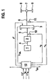
- Fig. 1 shows a drive unit for a motor vehicle.
- reference numeral 1 denotes an internal combustion engine, which is connected via a shaft 4 with an automatic transmission 2.
- the automatic transmission 2 is formed in a particularly advantageous manner as a continuously variable transmission.
- the automatic transmission 2 is connected via a clutch input shaft 5, a clutch 3, a clutch output shaft 6, a differential 7 connected to drive wheels 8, 9 for driving the motor vehicle.
- a clutch control 12 is provided which adjusts the contact pressure in the clutch 3 by specifying a setpoint contact pressure p *.
- the contact pressure is synonymous with a contact pressure with which the clutch 3 is compressed.
- Input variables in the clutch control 12 are the speed n E of the clutch input shaft 5, which is measured by means of a speed sensor 10, the speed n A of the clutch output shaft 6, which is measured with a speed sensor 11, the ratio i of the automatic transmission 2, a oil temperature ⁇ oIL of the clutch 3 and a target value .DELTA.n * for the clutch slip of the clutch 3 (setpoint clutch slip) and optionally torque T M of the engine 1 as well as information .DELTA.T M relating to the inaccuracy of the information on the torque T M of the engine 1.
- the torque T M of the internal combustion engine 1 and the information ⁇ T M about the inaccuracy of the information about the torque T M of the internal combustion engine 1 are provided, for example, by a motor controller (not shown).
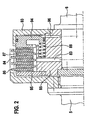
- Fig. 2 shows a coupling 3 in an exemplary embodiment.
- reference numeral 83 denotes a lubricating oil supply for hydraulic oil
- reference numeral 84 an outer cam
- reference numeral 85 an inner cam
- reference numeral 86 an outer disc
- reference numeral 87 an inner disc
- reference numeral 88 a return spring
- reference numeral 93 a cylinder
- reference numeral 94 a piston
- reference numeral 95 a pressure plate
- reference numeral 96 a pressure medium supply.
- On Conversemit Congress 84 which is connected to the clutch input shaft 5, outer plates 86, in an advantageous embodiment steel plates without friction lining arranged.
- the associated with the clutch output shaft 6 mecanical matter 85 receives the inner plates 87, which are coated with a friction lining.
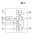
- the differential former 20 has a differential former 20 and a pressure regulator 21 and optionally an adapter 22 and / or a protective device 81.
- the pressure regulator 21 is explained in more detail in FIG. 4 and the adapter in FIG.
- the differential former 20 determines the clutch slip .DELTA.n, which is input to the pressure regulator 21. Further input variables of the pressure regulator 21 are the desired clutch slip ⁇ n *, the engine torque T M , the ratio i of the automatic transmission 2 and the friction coefficient ⁇ .
- the friction coefficient ⁇ is formed by means of the adapter 22.
- Input variables in the optional adapter 22 are the desired clutch slip ⁇ n *, the ratio i of the automatic transmission 2, the torque T M of the internal combustion engine 1, information ⁇ T M on the inaccuracy of the information about the torque T M of the internal combustion engine 1 and a differential torque T R. , which is formed by the pressure regulator 21.
- a corrected engine torque T MK is another output variable of the adapter 22.
- the pressure regulator 21 also forms the setpoint contact pressure p *.
- the clutch control 12 optionally has a protective device 81 for protecting the drive assembly, in particular the automatic transmission 2, against torque surges.
- Output of the protective device 81 is an impact torque T S.
- the contact pressure in a belt transmission can be increased accordingly.
- the required contact pressure in the belt transmission is to be increased as a function of the impact torque T S.
- Fig. 4 shows the internal structure of the pressure regulator 21.
- the pressure regulator 21 has a filter 31 for filtering the clutch slip ⁇ n.
- a summer 36 By means of a summer 36, the difference between the desired clutch slip ⁇ n * and the formed by the filter 31 filtered clutch slip .DELTA.n. This difference is negated by a negator 32 and is input to a controller 33, which is designed in an advantageous embodiment as a PID controller.
- Output variable of the regulator 33 is a differential torque T R.
- the difference torque T R is the input quantity in a minimum value generator 82.
- the minimum value generator 82 compares the difference torque T R and the impact torque T S and outputs the larger torque as the output value.
- the minimum of differential torque T R and impact torque T S is input to a selector 79.
- the engine torque T M is filtered and multiplied by means of a multiplier 90 with the ratio i of the automatic transmission 2.
- the engine torque T M thus filtered and multiplied by the ratio i of the automatic transmission 2 is fed to a selector 79.
- the calculated temperature ⁇ SL of the steel plates of the clutch 3 is input to the selector 79.
- the output of the selector 79 is the coupling torque T K to be transmitted by the clutch 3, which together with the friction coefficient ⁇ is the input value into an inverse clutch model 35.
- FIG. 5 shows a flow chart which is implemented on the selector 79 in an advantageous embodiment.
- the beginning of the sequence 100 is followed by a step 101, in which the temperature ⁇ SL of the steel disks of the clutch 3 is read.
- Steps 103 and 104 are followed by a query 105 in which it is queried whether the determination of the clutch torque T K to be transmitted by the clutch 3 should be ended as a function of the temperature of the clutch 3. If this is not the case, the query 105 is followed by the step 101. If, on the other hand, the query 105 follows the end 106 of the sequence
- A is the piston surface of the clutch 3
- r is the effective friction radius of the clutch 3
- Z R is the number of friction surfaces of the clutch 3
- F 0 is the minimum force required to transmit torque by means of the clutch 3.
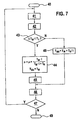
- Fig. 7 shows a flowchart as an implementation of the adapter 22.
- reference numeral 40 denotes the beginning of the process and reference numeral 49 the end of the process.
- a step 41 the information T M on the engine torque, the information ⁇ T M on the inaccuracy of the information about the engine torque T M , the difference torque T R , the target clutch slip ⁇ n * and the contact pressure p are read.
- a friction coefficient ⁇ is formed from the desired clutch slip ⁇ n * and the contact pressure p. This is done in an advantageous embodiment by means of a dependent of the contact pressure p friction coefficient slip characteristic. Such a characteristic is shown by way of example in FIG. 8 and designated by reference numeral 50.
- step 44 is followed by a step 45 in which the pressure-dependent friction coefficient slip characteristic 50 is changed so that the new value for the friction coefficient ⁇ and the target clutch slip ⁇ n * form a pair of values on the changed friction coefficient slip characteristic 51.
- Step 45 is illustrated by FIG.
- ⁇ 1 denotes the value for the coefficient of friction ⁇ for the valid contact pressure before execution of step 45
- ⁇ 2 denotes the value of the friction coefficient ⁇ for the valid contact pressure after execution of step 45.
- the friction coefficient ⁇ 1 is formed by means of the characteristic curve 50 as a function of the desired clutch slip ⁇ n * (see step 42).
- step 45 the friction coefficient clutch slip characteristic 50 is changed so as to give a friction coefficient clutch slip characteristic 51 in which the value ⁇ 2 and the target clutch slip ⁇ n * are a value pair.
- step 46 or the step 48 is followed by a query 47, in which it is queried whether the previous sequence should be repeated. If this is the case, then step 41 follows. If this is not the case, then the. Process finished.
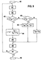
- step 9 shows a modification of the flowchart from FIG. 7.
- query 43 is not followed by step 48 but by a query 60.
- Query 60 queries whether .DELTA.T M > T 2 is satisfied, where T 2 is a second tolerance value. If this condition is fulfilled, then step 48 follows. If the condition is not met, step 46 is carried out.
- FIGS. 10 and 11 illustrate the differences between the flowcharts according to FIGS. 7 and 9.
- the information ⁇ T M about the inaccuracy of the information about the engine torque T M of the internal combustion engine 1 is shown on the abscissa.
- the ordinates in Figs. 10 and 11 indicate which steps are performed.
- the value -1 symbolizes the execution of steps 44 and 45
- the value 1 the execution of step 48
- the value 0 neither the execution of steps 44 and 45 nor step 48.
- the query 43 in FIG. 7 corresponds to a binary switch
- the combination of the queries 43 and 60 in FIG. 9 corresponds to a three-point switch.
- instead of these two simple types of switches even more complicated switching operations, such as flowing transitions, which can be carried out, for example, by fuzzy techniques, are conceivable.
Landscapes
- Engineering & Computer Science (AREA)
- General Engineering & Computer Science (AREA)
- Physics & Mathematics (AREA)
- Fluid Mechanics (AREA)
- Mechanical Engineering (AREA)
- Hydraulic Clutches, Magnetic Clutches, Fluid Clutches, And Fluid Joints (AREA)
Abstract
Description
- Die Erfindung betrifft ein Verfahren und eine Einrichtung zum Betrieb einer Kupplung zwischen einem Verbrennungsmotor und zumindest einem Antriebsrad eines Fahrzeugs, wobei durch Zusammenpressen der Kupplung mit einer Anpreßkraft oder einem Anpreßdruck ein Moment zwischen dem Verbrennungsmotor und dem Antriebsrad übertragen wird.
- Wird eine Kupplung schlupfend betrieben, so können bei bekanntem Reibkoeffizient des Kupplungsbelags Rückschlüsse auf das übertragene Kupplungsmoment gezogen werden. Diese Momenteninformation soll zur Bestimmung des Getriebeeingangsmoments herangezogen werden. Eine genaue Erfassung des Getriebeeingangsmoments ist insbesondere bei stufenlosen Automatikgetrieben (CVT) von Bedeutung, damit der Sicherheitsdruck bei der Bandspannungsregelung von Umschlingungsgetrieben reduziert und der Getriebewirkungsgrad erhöht werden kann.
- Die US 5 403 250 offenbart ein Verfahren zum Betrieb einer Kupplung zwischen einem Verbrennungsmotor und einem Antriebsrad eines Fahrzeugs, bei dem durch Zusammenpressen der Kupplung ein Moment zwischen dem Verbrennungsmotor und dem Antriebsrad übertragen wird und der Anpressdruck der Kupplung in Abhängigkeit von einer gemessen Temperatur der Kupplung gesteuert oder geregelt wird. In Abhängigkeit von der gemessenen Temperatur der Kupplung und vom Sollwert für den Kupplungsschlupf wird aus einem Diagramm ein Wert für den Reibungskoeffizienten der Kupplung abgelesen.
- Aus der US 4 072 220 ist eine Steuervorrichtung zur Betätigung einer Reibungskupplung in einem Kraftfahrzeug bekannt, bei der ein Kupplungssteller in Abhängigkeit von einer Drosselklappenstellung betätigt wird. Die Steuervorrichtung ist mit einem Temperatur-Sensor verbunden, der ein Wachsmaterial aufweist, das sich bei Erwärmung der Kupplung ausdehnt und einen mit der Steuervorrichtung elektrisch verbundenen Schalter betätigt.
- Die DE 198 51 341 A1 offenbart ein Verfahren zur Differenzdrehzahlregelung einer Kupplung, bei dem eine Solldrehzahldifferenz zwischen Eingangs- und Ausgangsseite der Kupplung als Führungsgröße und die aktuelle Drehzahlgröße als Regelgröße zur Regelung des Kupplungsschlupfes verwandt wird. Aus der Getriebeöltemperatur wird in Verbindung mit einem mathematisch-physikalischem Modell des Wärmeeintrags im Schlupfbetrieb der Reibschlussverbindung eine Temperaturüberwachung der Reibschlussverbindung durchgeführt, um eine Beschädigung der Kupplungsbeläge zu vermeiden.
- Es ist Aufgabe der Erfindung, den Betrieb einer Kupplung zu verbessern.
- Diese Aufgabe wird durch ein Verfahren bzw. eine Einrichtung zum Betrieb einer Kupplung zwischen einem Verbrennungsmotor und zumindest einem Antriebsrad eines Fahrzeugs, wobei durch Zusammenpressen der Kupplung mit einer Anpresskraft oder einem Anpressdruck ein Moment zwischen dem Verbrennungsmotor und dem Antriebsrad übertragen wird, gemäß Anspruch 1 bzw. gemäß Anspruch 6 gelöst, indem die Anpresskraft oder der Anpressdruck in Abhängigkeit von einer Temperatur einer Reibfläche der Kupplung gesteuert oder geregelt wird, wobei die Temperatur der Reibfläche der Kupplung mittels eines Temperaturmodels berechnet wird, in dem eine mathematische Beziehung zwischen der zu berechnenden Temperatur der Reibfläche der Kupplung und anderen Parametern, insbesondere einer erfassten Temperatur von Öl zur Schmierung oder Kühlung der Kupplung implementiert ist.
- In vorteilhafter Ausgestaltung der Erfindung wird das zu übertragende Moment zwischen dem Verbrennungsmotor und dem Antriebsrad um einen vorgegebenen Wert erhöht, wenn die Temperatur einer Reibfläche der Kupplung über einem Schwellenwert liegt.
- In weiterhin vorteilhafter Ausgestaltung der Erfindung wird die Anpreßkraft oder der Anpreßdruck in Abhängigkeit eines Kupplungsschlupfes in der Kupplung bei Übertragung des Momentes zwischen dem Verbrennungsmotor und dem Antriebsrad und einem Soll-Kupplungsschlupf geregelt, insbesondere wenn die Temperatur einer Reibfläche der Kupplung kleiner oder gleich dem Schwellenwert ist.
- In weiterhin vorteilhafter Ausgestaltung der Erfindung wird die Anpreßkraft oder der Anpreßdruck in Abhängigkeit der Differenz zwischen dem Kupplungsschlupf und dem Soll-Kupplungsschlupf geregelt, insbesondere wenn die Temperatur einer Reibfläche der Kupplung kleiner oder gleich dem Schwellenwert ist.
- In weiterhin vorteilhafter Ausgestaltung der Erfindung wird die Anpreßkraft oder der Anpreßdruck mittels eines inversen Kupplungsmodells geregelt, das die Anpreßkraft oder den Anpreßdruck in Abhängigkeit des über die Kupplung übertragenen Momentes errechnet.
- Die erfindungsgemäße Einrichtung zum Betrieb einer Kupplung zwischen einem Verbrennungsmotor und zumindest einem Antriebsrad eines Fahrzeugs, wobei durch Zusammenpressen der Kupplung mit einer Anpreßkraft oder einem Anpreßdruck ein Moment zwischen dem Verbrennungsmotor und dem Antriebsrad übertragen wird, weist einen Druckregler zur Steuerung oder Regelung der Anpreßkraft oder des Anpreßdrucks in Abhängigkeit der Temperatur einer Reibfläche der Kupplung auf, wobei
- Mittel zur Bestimmung der Temperatur einer Reibfläche der Kupplung mittels eines Temperaturmodells, in dem eine mathematische Beziehung zwischen der Temperatur der Reibfläche und anderen erfassten Parametern implementiert ist, vorgesehen sind.
- In weiterhin vorteilhafter Ausgestaltung der Erfindung weißt der Druckregler einen Regler zur Regelung der Anpreßkraft oder des Anpreßdrucks in Abhängigkeit eines Kupplungsschlupfes in der Kupplung bei Übertragung des Momentes zwischen dem Verbrennungsmotor und dem Antriebsrad und einem Soll-Kupplungsschlupf auf.
- In weiterhin vorteilhafter Ausgestaltung der Erfindung weißt der Druckregler ein inverses Kupplungsmodell zur Errechnung der Anpreßkraft oder des Anpreßdrucks in Abhängigkeit des über die Kupplung übertragenen Momentes auf.
- In weiterhin vorteilhafter Ausgestaltung der Erfindung ist der Reibkoeffizient der Kupplung ein Parameter des inversen Kupplungsmodells.
- In weiterhin vorteilhafter Ausgestaltung der Erfindung ist ein Adaptierer zur Adaption des Reibkoeffizienten der Kupplung vorgesehen.
- Weitere Einzelheiten und Vorteile ergeben sich aus nachfolgender Beschreibung von Ausführungsbeispielen. Im einzelnen zeigen:
- Fig. 1
- ein Antriebsaggregat für ein Kraftfahrzeug
- Fig. 2
- eine Kupplung
- Fig. 3
- eine Kupplungssteuerung
- Fig. 4
- einen Druckregler
- Fig. 5
- einen Ablaufplan
- Fig. 6
- eine Kennlinie
- Fig. 7
- einen Ablaufplan
- Fig. 8
- eine Reibkoeffizient-Schlupf-Kennline
- Fig. 9
- einen Ablaufplan
- Fig. 10
- eine Erläuterung des Ablaufplans gemäß Fig. 4
- Fig. 11
- eine Erläuterung des Ablaufplans gemäß Fig. 6
- Fig. 1 zeigt ein Antriebsaggregat für ein Kraftfahrzeug. Dabei bezeichnet Bezugszeichen 1 einen Verbrennungsmotor, der über eine Welle 4 mit einem Automatikgetriebe 2 verbunden ist. Das Automatikgetriebe 2 ist im besonders vorteilhafter Weise als stufenloses Umschlingungsgetriebe ausgebildet. Das Automatikgetriebe 2 ist über eine Kupplungs-Eingangswelle 5, eine Kupplung 3, eine Kupplungs-Ausgangswelle 6, ein Differential 7 mit Antriebsrädern 8, 9 zum Antrieb des Kraftfahrzeugs verbunden. Durch Zusammenpressen der Kupplung 3 mit einem Anpreßdruck p ist das über die Kupplung 3 übertragende Moment einstellbar. Zur Einstellung des über die Kupplung 3 übertragenden Moments ist eine Kupplungsteuerung 12 vorgesehen, die durch Vorgabe eines Soll-Anpreßdrucks p* den Anpreßdruck in der Kupplung 3 einstellt. Der Anpreßdruck ist synonym für eine Anpreßkraft mit der die Kupplung 3 zusammengepreßt wird.
- Eingangsgrößen in die Kupplungssteuerung 12 sind die Drehzahl nE der Kupplungs-Eingangswelle 5, die mittels eines Drehzahlsensors 10 gemessen wird, die Drehzahl nA der Kupplungs-Ausgangswelle 6, die mit einem Drehzahlsensor 11 gemessen wird, die Übersetzung i des Automatikgetriebes 2, eine Öltemperatur ϑOIL der Kupplung 3 und ein Sollwert Δn* für den Kupplungsschlupf der Kupplung 3 (Soll-Kupplungsschlupf) sowie optional das Moment TM des Verbrennungsmotors 1 sowie Information ΔTM über die Ungenauigkeit der Information über das Moment TM des Verbrennungsmotors 1. Der Kupplungsschlupf Δn ist definiert als

- Das Moment TM des Verbrennungsmotors 1 sowie die Information ΔTM über die Ungenauigkeit der Information über das Moment TM des Verbrennungsmotors 1 werden zum Beispiel von einer nicht dargestellten Motorsteuerung bereitgestellt.
- Fig. 2 zeigt eine Kupplung 3 in beispielhafter Ausgestaltung. Dabei bezeichnet Bezugszeichen 83 eine Schmierölzuführung für Hydrauliköl, Bezugszeichen 84 einen Außenmitnehmer, Bezugszeichen 85 einen Innenmitnehmer, Bezugszeichen 86 eine Außenlamelle, Bezugszeichen 87 eine Innenlamelle, Bezugszeichen 88 eine Rückholfeder, Bezugszeichen 93 einen Zylinder, Bezugszeichen 94 einen Kolben, Bezugszeichen 95 eine Druckplatte und Bezugszeichen 96 eine Druckmittelzuführung. Am Außenmitnehmer 84, welcher mit der Kupplungs-Eingangswelle 5 verbunden ist, sind Außenlamellen 86, in vorteilhafter Ausgestaltung Stahllamellen ohne Reibbelag, angeordnet. Der mit der Kupplungs-Ausgangswelle 6 verbundene Innenmitnehmer 85 nimmt die Innenlamellen 87 auf, die mit einem Reibbelag beschichtet sind. Bei Einleitung von Hydrauliköl mit einem definierten Druckniveau über die Druckmittelzuführung 96 in den Zylinder 93 bewegt sich der Kolben 94 gegen die Kraft der Rückholfeder 88 in Richtung der Druckplatte 95 und drückt das Lamellenpaket, daß aus Innen- und Außenlamellen 87 und 86 besteht, zusammen. Zur Kühlung des Lamellenpakets wird über die Schmierölzuführung 83 Hydrauliköl zu den Innen- und Außenlamellen 87 und 86 geleitet. Die Temperatur des Schmieröls wird der Kupplungssteuerung 12 als Öltemperatur ϑOIL zugeführt.
- Fig. 3 zeigt die Kupplungssteuerung 12. Sie weist einen Differenzbildner 20 und einen Druckregler 21 sowie optional einen Adaptierer 22 und/oder eine Schutzeinrichtung 81 auf. Der Druckregler 21 ist in Fig. 4 und der Adaptierer in Fig. 7 näher erläutert. Der Differenzbildner 20 ermittelt den Kupplungsschlupf Δn, der Eingangsgröße in den Druckregler 21 ist. Weitere Eingangsgrößen des Druckreglers 21 sind der Soll-Kupplungsschlupf Δn*, das Motormoment TM, die Übersetzung i des Automatikgetriebes 2 und der Reibkoeffizient µ. Der Reibkoeffizient µ wird mittels des Adaptierers 22 gebildet. Eingangsgrößen in den optionalen Adaptierer 22 sind der Soll-Kupplungsschlupf Δn*, die Übersetzung i des Automatikgetriebes 2, das Moment TM des Verbrennungsmotors 1, Information ΔTM über die Ungenauigkeit der Information über das Moment TM des Verbrennungsmotors 1 sowie ein Differenzmoment TR, das vom Druckregler 21 gebildet wird. Neben dem Reibkoeffizient µ ist ein korrigiertes Motormoment TMK eine weitere Ausgangsgröße des Adaptierers 22. Der Druckregler 21 bildet ferner den Soll-Anpreßdruck p*.
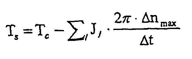
- Die Kupplungssteuerung 12 weist optional eine Schutzeinrichtung 81 zum Schutz des Antriebsaggregats, insbesondere des Automatikgetriebes 2, vor Drehmomentstößen auf. Ausgangsgröße der Schutzeinrichtung 81 ist ein Stoßmoment TS. Das Stoßmoment TS errechnet sich in vorteilhafter Ausgestaltung gemäß
- Dabei ist
- J1
- das Trägheitsmoment einer 1-ten Komponente des Antriebsaggregats auf der Seite der Kupplung 3, auf der der Verbrennungsmotor 1 angeordnet ist.
- Δnmax
- der maximal zulässige Kupplungsschlupf
- Tc
- ein konstantes Moment
- Δt
- die Zeitdauer, in der ein Momentenstoß zu einer Erhöhung des Schlupfes führt.
- Ist die Schlupfdauer Δt von untergeordneter Bedeutung, so kann das Stoßmoment TS gleich dem konstanten Moment Tc gesetzt werden.
- In vorteilhafter Ausgestaltung ist vorgesehen, das Stoßmoment TS an eine Getriebesteuerung zu übertragen, so daß z.B. der Anpreßdruck in einem Umschlingungsgetriebe entsprechend erhöht werden kann. Der erforderliche Anpreßdruck im Umschlingungsgetriebe ist in Abhängigkeit des Stoßmoments TS anzuheben.
- Fig. 4 zeigt den inneren Aufbau des Druckreglers 21. Der Druckregler 21 weist einen Filter 31 zur Filterung des Kupplungsschlupfes Δn auf. Mittels eines Summierers 36 wird die Differenz zwischen dem Soll-Kupplungsschlupf Δn* und dem mittels des Filters 31 gefilterten Kupplungsschlupfes Δn gebildet. Diese Differenz wird mittels eines Negierers 32 negiert und ist Eingangsgröße in einen Regler 33, der in vorteilhafter Ausgestaltung als PID-Regler ausgeführt ist. Ausgangsgröße des Reglers 33 ist ein Differenzmoment TR. Das Differenzmoment TR ist Eingangsgröße in einem Minimalwertbildner 82. Der Minimalwertbildner 82 vergleicht das Differenzmoment TR und das Stoßmoment TS und gibt das größere Moment als Ausgangswert aus. Das Minimum von Differenzmoment TR und Stoßmoment TS ist Eingangsgröße in einem Auswähler 79.
- Mittels eines Filters 34 wird das Motormoment TM gefiltert und mittels eines Multiplizierers 90 mit der Übersetzung i des Automatikgetriebes 2 multipliziert. Das so gefilterte und mit der Übersetzung i des Automatikgetriebes 2 multiplizierte Motormoment TM wird einem Auswähler 79 zugeführt.
- Es ist weiterhin ein Temperaturmodell 78 zur Berechnung der Temperatur ϑSL der Stahllamellen der Kupplung 3 vorgesehen. In beispielhafter Ausgestaltung ist der Zusammenhang

in dem Temperaturmodell 78 implementiert. Dabei ist - ϑSL
- die Temperatur der Stahllamellen
- ϑOIL
- die Temperatur des Hydrauliköls
- AR
- die Reibfläche der Stahllamellen
- ZR
- die Anzahl der Reibflächen
- mSL
- die Masse der Stahllamellen
- CSL
- die Wärmekapazität der Stahllamellen
- tn
- den aktuelle Zeitpunkt
- α
- die Wärmeübergangszahl
- Die so errechnete Temperatur ϑSL der Stahllamellen der Kupplung 3 ist Eingangsgröße in den Auswähler 79. Ausgangsgröße des Auswählers 79 ist das von der Kupplung 3 zu übertragende Kupplungsmoment TK, das zusammen mit dem Reibekoeffizienten µ Eingangswert in ein inverses Kupplungsmodell 35 ist.
- Figur 5 zeigt einen Ablaufplan, der in vorteilhafter Ausgestaltung auf dem Auswähler 79 implementiert ist. Dem Beginn des Ablaufs 100 folgt ein Schritt 101, in dem die Temperatur ϑSL der Stahllamellen der Kupplung 3 eingelesen wird. Dem Schritt 101 folgt eine Abfrage 102 in der abgefragt wird, ob

wobei ϑSllim ein Schwellenwert für Temperatur ϑSL der Stahllamellen der Kupplung 3 ist. Ist die Bedingung
erfüllt, so folgt der Abfrage 102 ein Schritt 103, in dem das von der Kupplung zu 3 zu übertragende Kupplungsmoment TK gemäß
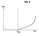
berechnet wird, wobei Toffset z. B. gemäß einem Zusammenhang bestimmt wird, wie er beispielhaft in Fig. 6 dargestellt ist. - Ist die Bedingung

dagegen nicht erfüllt, so folgt der Abfrage 102 ein Schritt 104, in dem das von der Kupplung 3 zu übertragende Kupplungsmoment TK gemäß
berechnet wird. - Den Schritten 103 bzw. 104 folgt eine Abfrage 105, in der abgefragt wird, ob die Bestimmung des von der Kupplung 3 zu übertragende Kupplungsmomentes TK in Abhängigkeit der Temperatur der Kupplung 3 beendet werden soll. Ist dies nicht der Fall, so folgt der Abfrage 105 der Schritt 101. Ist es dagegen der Fall, so folgt der Abfrage 105 das Ende 106 des Ablaufs
- Im inversen Kupplungsmodel 35 ist in beispielhafter Ausgestaltung folgende Gleichung implementiert:

- Dabei ist A die Kolbenfläche der Kupplung 3, r der effektive Reibradius der Kupplung 3, ZR die Anzahl der Reibflächen der Kupplung 3 und F0 die minimal notwendige Kraft zur Drehmomentübertragung mittels der Kupplung 3.
- Fig. 7 zeigt einen Ablaufplan, als Implementierung des Adaptierers 22. Dabei bezeichnet Bezugszeichen 40 den Anfang des Ablaufs und Bezugszeichen 49 das Ende des Ablaufs. In einem Schritt 41 werden die Information TM über das Motormoment, die Information ΔTM über die Ungenauigkeit der Information über das Motormoment TM, das Differenzmoment TR, der Soll-Kupplungsschlupf Δn* und der Anpreßdruck p eingelesen.
- In einem nächsten Schritt 42 wird ein Reibkoeffizient µ aus dem Soll-Kupplungsschlupf Δn* und dem Anpreßdruck p gebildet. Dies erfolgt in vorteilhafter Ausgestaltung mittels einer vom Anpreßdruck p abhängigen Reibkoeffizient-Schlupf-Kennlinie. Eine solche Kennlinie ist beispielhaft in Fig. 8 dargestellt und mit Bezugszeichen 50 bezeichnet.
- Dem Schritt 42 folgt die Abfrage 43 in der abgefragt wird, ob

wobei T1 ein (erster) Toleranzwert ist. Ist
so folgt ein Schritt 44, in dem ein neuer Reibkoeffizient µ der Kupplung gemäß
sowie ein korrigiertes Motormoment TMK gemäß
gebildet wird. - Dem Schritt 44 folgt ein Schritt 45 in dem die vom anpreßdruckabhängigen Reibkoeffizient-Schlupf-Kennlinie 50 derart verändert wird, daß der neue Wert für den Reibkoeffizient µ und der Soll-Kupplungsschlupf Δn* ein Wertepaar auf der veränderten Reibkoeffizient-Schlupf-Kennlinie 51 bilden. Schritt 45 wird durch Fig. 8 verdeutlicht. Dabei bezeichnet µ1 den Wert für den Reibkoeffizienten µ für den gültigen Anpreßdruck vor Ausführung des Schritts 45 und µ2 den Wert des Reibkoeffizienten µ für den gültigen Anpreßdruck nach Ausführung des Schritts 45. Der Reibkoeffizient µ1 wird mittels der Kennlinie 50 in Abhängigkeit des Soll-Kupplungsschlupfes Δn* gebildet (siehe Schritt 42). Im Schritt 45 wird in die Reibkoeffizient-Kupplungsschlupf-Kennlinie 50 so verändert, daß sich eine Reibkoeffizient-Kupplungsschlupf-Kennlinie 51 ergibt, auf der der Wert µ2 und der Soll-Kupplungsschlupf Δn* ein Wertepaar sind.
- Ist

nicht erfüllt, so folgt statt Schritt 44 ein Schritt 48, in dem ein korrigiertes Motormoment TMK gleich der Summe aus durch den Verbrennungsmotor 1 erzeugte Motormoment TM und dem durch die Übersetzung i des Automatikgetriebes 2 dividierten Differenzmoments TR gesetzt wird:
- Dem Schritt 46 bzw. dem Schritt 48 folgt eine Abfrage 47, in der abgefragt wird, ob der vorangegangene Ablauf wiederholt werden soll. Ist dies der Fall, so folgt Schritt 41. Ist dies nicht der Fall, so wird der. Ablauf beendet.
- Fig.9 zeigt eine Abwandlung des Ablaufplans aus Fig. 7. Dabei folgt der Abfrage 43 nicht der Schritt 48 sondern eine Abfrage 60. Mit der Abfrage 60 wird abgefragt, ob

erfüllt ist wobei T2 ein zweiter Toleranzwert ist. Ist diese Bedingung erfüllt, so folgt Schritt 48. Ist die Bedingung dagegen nicht erfüllt, erfolgt Schritt 46. - Fig. 10 und Fig. 11 verdeutlichen die Unterschiede zwischen den Ablaufplänen gemäß Fig. 7 und Fig. 9. Dabei ist auf der Abszisse die Information ΔTM über die Ungenauigkeit der Information über das Motormoment TM des Verbrennungsmotors 1 dargestellt. Die Ordinaten in Fig. 10 und Fig. 11 geben an, welche Schritte ausgeführt werden. Dabei symbolisiert der Wert -1 die Ausführung der Schritte 44 und 45, der Wert 1 die Ausführung des Schritts 48 und der Wert 0 weder die Ausführung der Schritte 44 und 45 noch des Schritts 48. Die Abfrage 43 in Fig. 7 entspricht einem binären Schalter. Die Kombination der Abfragen 43 und 60 in Fig. 9 entspricht einem Dreipunkt-Schalter. Anstelle dieser beiden einfachen Schaltertypen sind selbstverständlich auch komplizierterer Schaltvorgänge, wie etwa fließende Übergänge, die z.B. durch Fuzzy-Techniken ausgeführt werden können, denkbar.
-
- 1
- Motor
- 2
- Automatikgetriebe
- 3
- Kupplung
- 4
- Welle
- 5
- Kupplungs-Eingangswelle
- 6
- Kupplungs-Ausgangswelle
- 7
- Differential
- 8, 9
- Antriebsräder
- 10, 11
- Drehzahlsensoren
- 12
- Kupplungssteuerung
- 20
- Differenzbildner
- 21
- Druckregler
- 22
- Adaptierer
- 31, 34
- Filter
- 32
- Negierer
- 33
- Regler
- 35
- inverses Kupplungsmodell
- 36
- Summierer
- 40, 100
- Anfang des Ablaufs
- 41, 42, 44,
- Schritt
- 45, 46, 48,
- 101, 103,
- 104
- 43, 47, 60,
- Abfrage
- 102, 105
- 49
- Ende des Ablaufs
- 50, 51
- Reibkoeffizient-Schlupf-Kennlinie
- 78
- Temperaturmodell
- 79
- Auswähler
- 81
- Schutzeinrichtung
- 82
- Minimalwertbildner
- 83
- Schmierölzuführung
- 84
- Außenmitnehmer
- 85
- Innenmitnehmer
- 86
- Außenlamelle
- 87
- Innenlamelle
- 88
- Rückholfeder
- 90
- Multiplizierer
- 93
- Zylinder
- 94
- Kolben
- 95
- Druckplatte
- 96
- Druckmittelzuführung
- nE
- Drehzahl der Kupplungs-Eingangswelle
- nA
- Drehzahl der Kupplungs-Ausgangswelle
- TM
- Information über das Motormoment
- ΔTM
- Ungenauigkeit der Information über das Motormoment
- TR
- Differenzmoment (Reglerausgang)
- Tk
- Kupplungsmoment
- T1
- erster Toleranzwert
- T2
- zweiter Toleranzwert
- Δn
- Kupplungsschlupf
- Δn*
- Soll-Kupplungsschlupf
- i
- Übersetzung des Getriebes
- p
- Anpreßdruck
- p*
- Soll-Anpreßdruck
- µ, µ1, µ2
- Reibkoeffizient
- J1
- Trägheitsmoment des Antriebsaggregats auf der Seite der Kupplung 1, auf der der Verbrennungsmotor angeordnet ist.
- Δnmax
- maximal zulässige Kupplungsschlupf
- Tc
- konstantes Moment
- Δt
- Zeitdauer, in der ein Momentenstoß zu einer Erhöhung des Schlupfes führt
- ϑSL
- Temperatur der Stahllamellen der Kupplung
- ϑSLlim
- Schwellenwert für die Temperatur der Stahllamellen der Kupplung
- ϑOIL
- Temperatur des Hydrauliköls
- AR
- Reibfläche der Stahllamellen der Kupplung
- ZR
- Anzahl der Reibflächen der Kupplung
- mSL
- Masse der Stahllamellen der Kupplung
- CSL
- Wärmekapazität der Stahllamellen der Kupplung
- tn
- aktueller Zeitpunkt
- α
- Wärmeübergangszahl
- F0
- minimal notwendige Kraft zur Drehmomentübertragung mittels der Kupplung
- TS
- Stoßmoment
- Toffset
- keine Bezeichnung
Claims (11)
- Verfahren zum Betrieb einer Kupplung (3) zwischen einem Verbrennungsmotor (1) und zumindest einem Antriebsrad (8, 9) eines Fahrzeugs, wobei durch Zusammenpressen der Kupplung (3) mit einer Anpresskraft oder einem Anpressdruck (p) ein Moment zwischen dem Verbrennungsmotor (1) und dem Antriebsrad (8, 9) übertragen wird und die Anpresskraft oder der Anpressdruck (p) in Abhängigkeit von der Temperatur der Kupplung (3) gesteuert oder geregelt wird, dadurch gekennzeichnet, dass die Anpresskraft oder der Anpressdruck (p) in Abhängigkeit von einer Temperatur (ϑSL) einer Reibfläche der Kupplung (3) gesteuert oder geregelt wird und dass die Temperatur der Reibfläche der Kupplung mittels eines Temperaturmodells, in dem eine mathematische Beziehung zwischen der zu berechnenden Temperatur der Reibflächen der Kupplung und anderen Parametern, insbesondere einer erfassten Temperatur (ϑOIL) von Öl zur Schmierung oder Kühlung der Kupplung implementiert ist, berechnet wird.
- Verfahren nach Anspruch 1,
dadurch gekennzeichnet,
daß das zu übertragende Moment zwischen dem Verbrennungsmotor (1) und dem Antriebsrad (8, 9) um einen vorgegebenen Wert erhöht wird, wenn die Temperatur einer Reibfläche der Kupplung (3) über einem Schwellenwert liegt. - Verfahren nach Anspruch 1, oder 2,
dadurch gekennzeichnet,
daß die Anpreßkraft oder der Anpreßdruck (p) in Abhängigkeit eines Kupplungsschlupfes in der Kupplung (3) bei übertragung des Momentes zwischen dem Verbrennungsmotor (1) und dem Antriebsrad (8, 9) und einem Soll-Kupplungsschlupf geregelt wird, insbesondere wenn die Temperatur einer Reibfläche der Kupplung (3) kleiner oder gleich dem Schwellenwert ist. - Verfahren nach einem der vorhergehenden Ansprüche,
dadurch gekennzeichnet,
daß die Anpreßkraft oder der Anpreßdruck (p) in Abhängigkeit der Differenz zwischen dem Kupplungsschlupf und dem Soll-Kupplungsschlupf geregelt wird, insbesondere wenn die Temperatur einer Reibfläche der Kupplung (3) kleiner oder gleich dem Schwellenwert ist. - Verfahren nach einem der vorhergehenden Ansprüche,
dadurch gekennzeichnet,
daß die Anpreßkraft oder der Anpreßdruck (p) mittels eines inversen Kupplungsmodells geregelt wird, das die Anpreßkraft oder den Anpreßdruck (p) in Abhängigkeit des über die Kupplung (3) übertragenen Momentes errechnet. - Einrichtung zum Betrieb einer Kupplung (3) zwischen einem Verbrennungsmotor (1) und zumindest einem Antriebsrad (8, 9) eines Fahrzeugs, wobei durch Zusammenpressen der Kupplung (3) mit einer Anpresskraft oder einem Anpressdruck (p) ein Moment zwischen dem Verbrennungsmotor (1) und dem Antriebsrad (8, 9) übertragen wird und ein Druckregler (21) zur Steuerung oder Regelung der Anpresskraft oder des Anpressdrucks (p) in Abhängigkeit von der Temperatur der Kupplung (3) vorgesehen ist, dadurch gekennzeichnet, dass die Anpresskraft oder der Anpressdruck (p) in Abhängigkeit von einer Temperatur (ϑSL) einer Reibfläche der Kupplung (3) gesteuert oder geregelt wird und dass Mittel vorgesehen sind, die Temperatur der Reibfläche der Kupplung mittels eines Temperaturmodells, in dem eine mathematische Beziehung zwischen der zu berechnenden Temperatur der Reibflächen der Kupplung und anderen erfassten Parametern, insbesondere einer erfassten Temperatur (ϑOIL) von Öl zur Schmierung oder Kühlung der Kupplung implementiert ist, zu berechnen.
- Einrichtung nach Anspruch 6,
dadurch gekennzeichnet,
daß der Druckregler (21) einen Regler zur Regelung der Anpreßkraft oder des Anpreßdrucks (p) in Abhängigkeit eines Kupplungsschlupfes in der Kupplung (3) bei Übertragung des Momentes zwischen dem Verbrennungsmotor (1) und dem Antriebsrad (8, 9) und einem Soll-Kupplungsschlupf ausweist. - Einrichtung nach Anspruch 6 oder 7,
dadurch gekennzeichnet,
daß der Druckregler (21) ein inverses Kupplungsmodell zur Errechnung der Anpreßkraft oder des Anpreßdrucks (p) in Abhängigkeit des über die Kupplung (3) übertragenen Momentes aufweist. - Einrichtung nach Anspruch 8,
dadurch gekennzeichnet,
daß der Reibkoeffizient (µ) der Kupplung (3) ein Parameter des inversen Kupplungsmodells ist. - Einrichtung nach Anspruch 9,
dadurch gekennzeichnet,
daß sie einen Adaptierer zur Adaption des Reibkoeffizienten (µ) der Kupplung (3) aufweist. - Einrichtung nach einem der Ansprüche 6 bis 10,
dadurch gekennzeichnet,
daß Druckregler (21) einen Auswähler zur, insbesondere von der Temperatur einer Reibfläche der Kupplung (3) abhängigen, Entscheidung, ob die Anpreßkraft oder der Anpreßdruck (p) unabhängig vom Kupplungsschlupf in der Kupplung (3) ermittelt wird, aufweist.
Applications Claiming Priority (3)
| Application Number | Priority Date | Filing Date | Title |
|---|---|---|---|
| DE10045758A DE10045758A1 (de) | 2000-09-15 | 2000-09-15 | Verfahren und Einrichtung zum Betrieb einer Kupplung |
| DE10045758 | 2000-09-15 | ||
| PCT/DE2001/003395 WO2002023066A1 (de) | 2000-09-15 | 2001-09-05 | Verfahren und einrichtung zum betrieb einer kupplung |
Publications (2)
| Publication Number | Publication Date |
|---|---|
| EP1320697A1 EP1320697A1 (de) | 2003-06-25 |
| EP1320697B1 true EP1320697B1 (de) | 2006-01-11 |
Family
ID=7656380
Family Applications (1)
| Application Number | Title | Priority Date | Filing Date |
|---|---|---|---|
| EP01974008A Expired - Lifetime EP1320697B1 (de) | 2000-09-15 | 2001-09-05 | Verfahren und einrichtung zum betrieb einer kupplung |
Country Status (4)
| Country | Link |
|---|---|
| EP (1) | EP1320697B1 (de) |
| JP (1) | JP4860894B2 (de) |
| DE (2) | DE10045758A1 (de) |
| WO (1) | WO2002023066A1 (de) |
Cited By (1)
| Publication number | Priority date | Publication date | Assignee | Title |
|---|---|---|---|---|
| WO2018211189A1 (fr) | 2017-05-15 | 2018-11-22 | Psa Automobiles Sa | Procede de controle d'un groupe motopropulseur pour la regulation thermique d'un circuit hydraulique |
Families Citing this family (11)
| Publication number | Priority date | Publication date | Assignee | Title |
|---|---|---|---|---|
| DE10316458B4 (de) * | 2002-04-10 | 2013-10-31 | Schaeffler Technologies AG & Co. KG | Getriebesteuerung und Verfahren zum Durchführen einer Reibwertadaption |
| JP2004150513A (ja) * | 2002-10-30 | 2004-05-27 | Aisin Seiki Co Ltd | クラッチ制御装置 |
| DE10306896B4 (de) * | 2003-02-18 | 2019-01-24 | Volkswagen Ag | Verfahren zur Steuerung des Betriebs einer Kupplung eines Kraftfahrzeuges |
| JP2007139129A (ja) * | 2005-11-21 | 2007-06-07 | Nissan Motor Co Ltd | クラッチ制御装置 |
| DE102008026554B4 (de) * | 2008-06-03 | 2022-12-15 | Magna powertrain gmbh & co kg | Verfahren zum Steuern einer Kupplungseinheit, sowie Drehmomentübertragungsanordnung |
| FR2933913B1 (fr) * | 2008-07-16 | 2011-01-14 | Renault Sas | Dispositif de commande adaptative a l'evolution de la caracteristique d'un embrayage en fonction de la temperature applique a un vehicule equipe d'un systeme 4x4 pilote. |
| DE102010029980A1 (de) * | 2010-06-11 | 2011-12-15 | Zf Friedrichshafen Ag | Verfahren zum Betreiben eines Reibschaltelements |
| DE102012204369B4 (de) | 2012-03-20 | 2015-10-29 | Robert Bosch Gmbh | Kraftmaschinenanordnung umfassend eine fluidbetätigte Kupplungsanordnung und eine Lamellenkupplung |
| EP3548225B1 (de) | 2016-11-30 | 2022-03-09 | Saint-Gobain Performance Plastics Rencol Limited | Einstellbare drehmomentanordnung |
| KR101886530B1 (ko) | 2016-12-12 | 2018-08-07 | 현대자동차주식회사 | 듀얼 클러치 변속기의 오일 제어시스템 및 그 제어방법 |
| DE102019204438B3 (de) * | 2019-03-29 | 2020-07-09 | Magna powertrain gmbh & co kg | Verfahren zum Steuern einer Kupplungseinheit |
Family Cites Families (11)
| Publication number | Priority date | Publication date | Assignee | Title |
|---|---|---|---|---|
| JPS5835887B2 (ja) * | 1975-06-25 | 1983-08-05 | 日産自動車株式会社 | ジドウクラツチニオケルクラツチバンノ マサツケイスウホシヨウソウチ |
| US4828089A (en) * | 1985-05-07 | 1989-05-09 | Eaton Corporation | Brake/clutch with direct liquid cooling |
| JP2769725B2 (ja) * | 1989-09-30 | 1998-06-25 | スズキ株式会社 | 連続可変変速機のクラッチ制御方法 |
| DE4100372A1 (de) * | 1991-01-09 | 1992-07-16 | Fichtel & Sachs Ag | Anordnung zur regelung des schlupfs einer automatisierten reibungskupplung |
| DE4241995C2 (de) * | 1992-12-12 | 1996-07-11 | Daimler Benz Ag | Anordnung zur Einstellung des Kupplungsschlupfes einer im Kraftfluß einem Antriebsmotor eines Kraftfahrzeuges nachgeordneten Reibungskupplung |
| SE509655C2 (sv) * | 1994-02-11 | 1999-02-22 | Luk Getriebe Systeme Gmbh | Hydrodynamisk vridmomentomvanlare |
| DE19602006A1 (de) * | 1995-01-28 | 1996-08-01 | Luk Getriebe Systeme Gmbh | Vorrichtung und ein Verfahren zur Ansteuerung eines Drehmomentübertragungssystems |
| JPH10196683A (ja) * | 1997-01-14 | 1998-07-31 | Komatsu Ltd | クラッチ式変速機のクラッチ負荷検出装置 |
| DE19851341A1 (de) * | 1998-11-06 | 2000-05-11 | Zahnradfabrik Friedrichshafen | Differenzdrehzahlregelung einer schaltbaren Reibschlußverbindung |
| JP2000205009A (ja) * | 1999-01-18 | 2000-07-25 | Nissan Motor Co Ltd | スロットル制御装置 |
| JP2000205008A (ja) * | 1999-01-18 | 2000-07-25 | Nissan Motor Co Ltd | スロットル制御装置 |
-
2000
- 2000-09-15 DE DE10045758A patent/DE10045758A1/de not_active Withdrawn
-
2001
- 2001-09-05 DE DE50108694T patent/DE50108694D1/de not_active Expired - Lifetime
- 2001-09-05 JP JP2002527678A patent/JP4860894B2/ja not_active Expired - Fee Related
- 2001-09-05 EP EP01974008A patent/EP1320697B1/de not_active Expired - Lifetime
- 2001-09-05 WO PCT/DE2001/003395 patent/WO2002023066A1/de not_active Ceased
Cited By (1)
| Publication number | Priority date | Publication date | Assignee | Title |
|---|---|---|---|---|
| WO2018211189A1 (fr) | 2017-05-15 | 2018-11-22 | Psa Automobiles Sa | Procede de controle d'un groupe motopropulseur pour la regulation thermique d'un circuit hydraulique |
Also Published As
| Publication number | Publication date |
|---|---|
| WO2002023066A1 (de) | 2002-03-21 |
| JP2004509297A (ja) | 2004-03-25 |
| EP1320697A1 (de) | 2003-06-25 |
| JP4860894B2 (ja) | 2012-01-25 |
| DE50108694D1 (de) | 2006-04-06 |
| DE10045758A1 (de) | 2002-03-28 |
Similar Documents
| Publication | Publication Date | Title |
|---|---|---|
| EP1238202B1 (de) | Verfahren und einrichtung zum betrieb einer kupplung | |
| EP1320697B1 (de) | Verfahren und einrichtung zum betrieb einer kupplung | |
| DE69521866T2 (de) | Automatisierte Kupplungsbetätigung und -Einstellung | |
| US20030134713A1 (en) | Method and device for operating a clutch | |
| DE102005061080A1 (de) | Verfahren und Vorrichtung zum Erkennen einer Schädigung einer Kupplung mit wenigstens zwei durch Reibeingriff Drehmoment übertragenden Bauteilen | |
| DE19702449A1 (de) | Vorrichtung zur Betätigung | |
| EP3464924B1 (de) | Fahrzeug sowie verfahren zum betreiben einer kupplung als anfahrelement | |
| EP1320673B1 (de) | Antriebsaggregat für ein fahrzeug | |
| DE4135969B4 (de) | Verfahren zum Steuern einer automatischen Startkupplung | |
| US6701241B2 (en) | Method and device for operating a clutch | |
| EP1775449B1 (de) | Antriebsstrang für ein Kraftfahrzeug und Verfahren zum Betreiben eines solchen Antriebsstrangs | |
| WO2022007992A1 (de) | Verfahren zur steuerung einer überschneidungsschaltung einer hydraulisch betätigten doppelkupplung | |
| EP1899631B1 (de) | Verfahren und vorrichtung zum überwachen der betriebssicherheit eines durch reibeingriff drehmoment übertragenden getriebes | |
| EP1706303A1 (de) | Verfahren zum Betrieb eines Antriebsstrangs eines Kraftfahrzeugs | |
| DE19750824C2 (de) | Verfahren zur Erfassung einer Grenzstellungsposition einer Kraftfahrzeugkupplung | |
| DE69023839T2 (de) | Stufenloses Getriebesystem mit zugehöriger Kupplungs- Steuerungs-Anordnung. | |
| DE102005057844A1 (de) | Verfahren zum Begrenzen des Drucks in einem hydrostatischen Kupplungsausrücksystem | |
| EP1683982A2 (de) | Verfahren und Vorrichtung zum Erkennen einer Schädigung einer Kupplung mit wenigstens zwei durch Reibeingriff Drehmoment übertragenden Bauteilen | |
| EP1461545B1 (de) | Steuerschaltung und verfahren zur erzeugung eines steuersignals zur steuerung eines stufenlos verstellbaren umschlingungsgetriebes | |
| DE102013009857B4 (de) | Verfahren zum Betreiben einer Kupplung eines Fahrzeugs und Fahrzeug | |
| DE10105322C1 (de) | Verfahren zum Betrieb eines Antriebsstrangs eines Kraftfahrzeugs | |
| DE102005040578B4 (de) | Steuerverfahren und Steuersystem zur Momentsteuerung eines Fahrzeugantriebsstranges | |
| DE10105321A1 (de) | Verfahren zum Betrieb eines Antriebsstrangs eines Kraftfahrzeugs | |
| DE102007034203A1 (de) | Verfahren und Vorrichtung zur Erkennung von Kupplungsverschleiß | |
| DE10055089A1 (de) | Verfahren und Einrichtung zum Betrieb einer Kupplung |
Legal Events
| Date | Code | Title | Description |
|---|---|---|---|
| PUAI | Public reference made under article 153(3) epc to a published international application that has entered the european phase |
Free format text: ORIGINAL CODE: 0009012 |
|
| 17P | Request for examination filed |
Effective date: 20030415 |
|
| AK | Designated contracting states |
Designated state(s): AT BE CH CY DE DK ES FI FR GB GR IE IT LI LU MC NL PT SE TR |
|
| RBV | Designated contracting states (corrected) |
Designated state(s): BE DE GB |
|
| 17Q | First examination report despatched |
Effective date: 20041103 |
|
| GRAP | Despatch of communication of intention to grant a patent |
Free format text: ORIGINAL CODE: EPIDOSNIGR1 |
|
| RIC1 | Information provided on ipc code assigned before grant |
Ipc: 7F 16H 61/14 A |
|
| GRAS | Grant fee paid |
Free format text: ORIGINAL CODE: EPIDOSNIGR3 |
|
| GRAA | (expected) grant |
Free format text: ORIGINAL CODE: 0009210 |
|
| AK | Designated contracting states |
Kind code of ref document: B1 Designated state(s): BE DE GB |
|
| REF | Corresponds to: |
Ref document number: 50108694 Country of ref document: DE Date of ref document: 20060406 Kind code of ref document: P |
|
| GBT | Gb: translation of ep patent filed (gb section 77(6)(a)/1977) |
Effective date: 20060413 |
|
| PLBE | No opposition filed within time limit |
Free format text: ORIGINAL CODE: 0009261 |
|
| STAA | Information on the status of an ep patent application or granted ep patent |
Free format text: STATUS: NO OPPOSITION FILED WITHIN TIME LIMIT |
|
| 26N | No opposition filed |
Effective date: 20061012 |
|
| PGFP | Annual fee paid to national office [announced via postgrant information from national office to epo] |
Ref country code: BE Payment date: 20100921 Year of fee payment: 10 |
|
| BERE | Be: lapsed |
Owner name: ROBERT *BOSCH G.M.B.H. Effective date: 20110930 |
|
| PG25 | Lapsed in a contracting state [announced via postgrant information from national office to epo] |
Ref country code: BE Free format text: LAPSE BECAUSE OF NON-PAYMENT OF DUE FEES Effective date: 20110930 |
|
| PGFP | Annual fee paid to national office [announced via postgrant information from national office to epo] |
Ref country code: GB Payment date: 20140923 Year of fee payment: 14 |
|
| GBPC | Gb: european patent ceased through non-payment of renewal fee |
Effective date: 20150905 |
|
| PG25 | Lapsed in a contracting state [announced via postgrant information from national office to epo] |
Ref country code: GB Free format text: LAPSE BECAUSE OF NON-PAYMENT OF DUE FEES Effective date: 20150905 |
|
| PGFP | Annual fee paid to national office [announced via postgrant information from national office to epo] |
Ref country code: DE Payment date: 20181121 Year of fee payment: 18 |
|
| REG | Reference to a national code |
Ref country code: DE Ref legal event code: R119 Ref document number: 50108694 Country of ref document: DE |
|
| PG25 | Lapsed in a contracting state [announced via postgrant information from national office to epo] |
Ref country code: DE Free format text: LAPSE BECAUSE OF NON-PAYMENT OF DUE FEES Effective date: 20200401 |