EP1321085B1 - Dispositif pour attacher des accessoires à un aspirateur et aspirateur comprenant un tel dispositif - Google Patents
Dispositif pour attacher des accessoires à un aspirateur et aspirateur comprenant un tel dispositif Download PDFInfo
- Publication number
- EP1321085B1 EP1321085B1 EP02009165A EP02009165A EP1321085B1 EP 1321085 B1 EP1321085 B1 EP 1321085B1 EP 02009165 A EP02009165 A EP 02009165A EP 02009165 A EP02009165 A EP 02009165A EP 1321085 B1 EP1321085 B1 EP 1321085B1
- Authority
- EP
- European Patent Office
- Prior art keywords
- vacuum cleaner
- fastening
- tool mounting
- exhaust
- mounting device
- Prior art date
- Legal status (The legal status is an assumption and is not a legal conclusion. Google has not performed a legal analysis and makes no representation as to the accuracy of the status listed.)
- Expired - Lifetime
Links
- 239000000126 substance Substances 0.000 claims description 6
- 238000001914 filtration Methods 0.000 claims description 3
- 230000008878 coupling Effects 0.000 description 2
- 238000010168 coupling process Methods 0.000 description 2
- 238000005859 coupling reaction Methods 0.000 description 2
- 238000010410 dusting Methods 0.000 description 2
- 238000004140 cleaning Methods 0.000 description 1
- 238000001746 injection moulding Methods 0.000 description 1
- 238000009434 installation Methods 0.000 description 1
- 239000000463 material Substances 0.000 description 1
- 230000004048 modification Effects 0.000 description 1
- 238000012986 modification Methods 0.000 description 1
- 229920003002 synthetic resin Polymers 0.000 description 1
- 239000000057 synthetic resin Substances 0.000 description 1
Images


Classifications
-
- A—HUMAN NECESSITIES
- A47—FURNITURE; DOMESTIC ARTICLES OR APPLIANCES; COFFEE MILLS; SPICE MILLS; SUCTION CLEANERS IN GENERAL
- A47L—DOMESTIC WASHING OR CLEANING; SUCTION CLEANERS IN GENERAL
- A47L9/00—Details or accessories of suction cleaners, e.g. mechanical means for controlling the suction or for effecting pulsating action; Storing devices specially adapted to suction cleaners or parts thereof; Carrying-vehicles specially adapted for suction cleaners
- A47L9/02—Nozzles
-
- A—HUMAN NECESSITIES
- A47—FURNITURE; DOMESTIC ARTICLES OR APPLIANCES; COFFEE MILLS; SPICE MILLS; SUCTION CLEANERS IN GENERAL
- A47L—DOMESTIC WASHING OR CLEANING; SUCTION CLEANERS IN GENERAL
- A47L9/00—Details or accessories of suction cleaners, e.g. mechanical means for controlling the suction or for effecting pulsating action; Storing devices specially adapted to suction cleaners or parts thereof; Carrying-vehicles specially adapted for suction cleaners
- A47L9/0009—Storing devices ; Supports, stands or holders
- A47L9/0018—Storing devices ; Supports, stands or holders integrated in or removably mounted upon the suction cleaner for storing parts of said suction cleaner
- A47L9/0027—Storing devices ; Supports, stands or holders integrated in or removably mounted upon the suction cleaner for storing parts of said suction cleaner specially adapted for holding the suction cleaning tools
Definitions
- the present invention relates to an accessory tool mounting device for a vacuum cleaner, and more particularly, to an accessory tool mounting device for a vacuum cleaner by which accessory tools can be detachably mounted on a main body of the vacuum cleaner in a more convenient manner and thus it is convenient to store and use the accessory tools.
- the invention also relates to a vacuum cleaner with such accessory mounting device.
- the vacuum cleaner 1 comprises a main body 10 in which a motor capable of generating suction power, etc. are installed, a connecting hose 14 which is detachably connected to a main body of the vacuum cleaner, an extension tube 11 of which an upper end is formed with a handle 13, and a suction portion 12 installed at a lower end of the extension tube 11.
- the connecting hose 14 is detachably connected to the main body through a fitting member 15 which is installed at an end of the connecting hose 14.
- the suction portion 12 installed at the lower end of the extension tube 11 is a portion that sucks air containing foreign substances while contacting a plane such as a floor with a gap therebetween and moving thereon.
- the suction portion 12 is configured to be detachably attached to the extension tube 11.
- the suction portion 12 is configured to suitably suck the air from the flat floor, it cannot be properly used, for example, in a corner region, for upholstery, or the like.
- accessory tools are provided together with the vacuum cleaner.
- Such accessory tools can be mainly divided into a crevice tool, a dusting brush, and an upholstery nozzle or tool. The accessory tools are used for desired places in a state where each of them is installed at the lower end of the extension tube 11 after separating the suction portion 12 therefrom.
- the accessory tools are provided separately from the vacuum cleaner, it is common for a user to store the accessory tools separately from the vacuum cleaner. In such a case where the accessory tools are separately stored, there is inconvenience in that in order to use the desired accessory tool, the user should seek it at a separate storage place and install it again.
- DE10046671 A discloses an accessory tool mounting door for a vacuum cleaner.
- the door is pivotally mounted to a main body of the vacuum cleaner and closes a compartment formed in the main body for receiving accessory tools.
- On the inner side of the door is formed a recess corresponding to the shape of another accessory tool for removably receiving and holding such other accessory tool.
- accessory tools for a vacuum cleaner can be stored together with a main body of the vacuum cleaner, it is possible to completely solve the problem of storing and using the accessory tools. That is, it will be apparent that if the accessory tools are configured to be detachably mounted on the main body of the vacuum cleaner, the problem of storing the accessory tools and the like can be solved. However, it will also be apparent that even when the accessory tools are configured to be detachably mounted on the main body of the vacuum cleaner, convenience of use and simplicity of mounting should be first considered.
- a primary object of the present invention is to make the storage and use of the accessory tools convenient by allowing the accessory tools provided together with the vacuum cleaner to be easily mounted on the main body of the vacuum cleaner.
- an accessory tool mounting device for use in a vacuum cleaner as defined in claim 1.
- both sides of the fastening end are further formed with a plurality of supporting bosses which elastically come into contact with inner surfaces of the fastening box member in a fore and aft direction of the vacuum cleaner.
- one of the supporting bosses is formed on the same side as and below the fastening boss of the fastening end, and the supporting boss and the fastening boss are formed to have a length corresponding to a width of the fastening box member in a transverse direction of the vacuum cleaner, thereby preventing the fastening end from playing in the transverse direction.
- the fastening boss of the fastening end has a length in the transverse direction which corresponds to the width of the fastening box member in the transverse direction so that the fastening boss is in close contact with the inner surface of the fastening box member.
- a vacuum cleaner including an accessory tool mounting device as defined in claim 5.
- FIG. 1 is a perspective view of a main body 50 of a vacuum cleaner on which an accessory tool mounting member 60 of the present invention is mounted
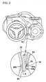
- FIG.2 is a side view of the main body of the vacuum cleaner.
- the main body 50 of the vacuum cleaner accommodates a suction motor for causing air containing foreign substances to be drawn.
- the foreign substances contained in the air which is drawn into the main body 50 by the suction motor are filtered out by means of a filtering device within the main body. Then, the filtered and clean air is exhausted to the exterior through exhaust portions 56 formed at lateral surfaces of the main body 50. Further, a pair of wheels 58 are mounted on the bottom of a rear region of the main body 50 so that the main body can be smoothly moved on a floor.
- An outer casing 51 of the main body 50 is formed integrally with wheel fender portions 52 for covering upper portions of the wheels 58. Further, the outer casing 51 of the main body 50 is formed integrally with exhaust-portion forming extensions 54 for forming upper parts of exhaust portions 56.
- the wheel fender portions 52 and the exhaust-portion forming extensions 54 integrally formed at lateral surfaces of the outer casing 51 of the main body 50 are formed to protrude outwardly from the outer casing such that they are formed to protrude from the lateral surfaces of the outer casing 51 at an angle of about 90° with respect to the lateral surfaces of the outer casing 51.
- an accessory tool mounting member 60 capable of detachably mounting accessory tools S, including a crevice tool Sa for sucking foreign substances in a narrow space, an upholstery tool Sb and the like, thereon is configured to be fitted between the wheel fender portion 52 and the exhaust-portion forming extension 54.
- the accessory tools S detachably mounted on the accessory tool mounting member 60 may include the other accessory tools such as a dusting brush in addition to the accessory tools shown in the figure.
- the space between the wheel fender portion 52 and the exhaust-portion forming extension 54 which take the shape of a partial segment of a circle is generally V-shaped.
- the accessory tool mounting member 60 according to the present invention is also V-shaped.
- Tubular mounting portions 62a, 62b into which the accessory tools S are fitted and secured are formed at a top surface on a side of the accessory tool mounting member 60. Therefore, the accessory tools S can be fitted into the mounting portions 62.
- a lower end of the accessory tool mounting member 60 is formed into a U-shaped fastening end 64.
- the fastening end 64 is a portion capable of being detachably coupled with a fastening box member 70 to be described later.
- Both side surfaces of the fastening end 64 of the accessory tool mounting member 60 are formed with a fastening boss 64a and a plurality of supporting bosses 64b, 64c.
- the accessory tool mounting member 60 formed by injection-molding synthetic resin materials has certain elasticity at the fastening end 64.
- the fastening box member 70 with which the fastening end 64 is detachably coupled is fixed between the wheel fender portion 52 and the exhaust-portion forming extension 54. It is preferred that the outer casing 51 of the main body be formed integrally with the fastening box member 70.
- the fastening box member 70 takes the shape of a box of which at least an upper end is open.
- the fastening box member 70 takes the shape of a cylinder with open upper and lower ends.
- the open upper end of the fastening box member is formed with an inwardly protruding catch protrusion 72.
- the fastening end 64 can be inserted into and fastened to the fastening box member 70. That is, when the fastening boss 64a formed at a side surface of the fastening end 64 is caught at the bottom of the catch protrusion 72, the accessory tool mounting member 60 becomes in a state where it is securely seated in the fastening box member 70. In this state, the supporting bosses 64b, 64c of the fastening end 64 come into contact with respective inner surfaces of the fastening box member 70 and thus it is possible to maintain the state where the mounting member 60 is fastened to the interior of the fastening box member 70.
- FIG. 4 that is a sectional view taken along line A-A of Fig. 2 , the catch protrusion 72 formed to protrude inwardly at the upper end of the fastening box member 70 and the fastening boss 64a caught at the bottom of the catch protrusion are formed on the right-hand side, whereas the lower supporting boss 64b is formed on the left-hand side.
- An interval between the fastening boss 64a and the supporting boss 64b substantially corresponds to a width Wa of the fastening box member 70 in a transverse direction of the main body.
- the present invention is not limited to the embodiment. It will be apparent that various modifications can be made to the coupling relationship between the fastening end 64 and the fastening box member 70. That is, it will be apparent that the U-shaped fastening end 64 formed at the lower end of the accessory tool mounting member 60 can be variously modified within the technical scope of the detachable coupling of the mounting member with the fastening box member 70.
- a pair of catch protrusions 172, 174 can be formed at both inner sides of an upper end of a fastening box member 170, and both sides of a fastening end 164 can be formed with fastening bosses 162, 163 to be caught at the bottom of the catch protrusions 172, 174, respectively.
- the fastening end 164 is elastically deformed inwardly so that the fastening end 164 can be detachably coupled with the fastening box member 170 in an elastic manner.
- the catch protrusion 72 or 172 and the fastening boss 64a or 162 are formed to have a full length corresponding to the width of the fastening box member 70 or 170 in the transverse direction so as to prevent any play from being produced in the transverse direction.
- bosses 64b, 64c may be formed as shown in FIG. 4 .
- the accessory tool mounting member 60 is detachably installed between the wheel fender portion 52 and the exhaust-portion forming extension 54 which are integrally formed with the outer casing 51 of the main body 50 of the vacuum cleaner.
- the accessory tools S are configured to be detachably mounted on the accessory tool mounting member 60.
- the plurality of accessory tools S are detachably mounted on the mounting member 60 and thus detachably coupled substantially to a side of the main body 50 of the vacuum cleaner.
- the plurality of accessory tools S are mounted on the main body 50 of the vacuum cleaner by using the mounting member 60 according to the present invention, it is possible to conveniently use the accessory tools at any time, if necessary.
- the plurality of accessory tools are in a state where they are mounted on the main body 50 of the vacuum cleaner.
- a proper accessory tool can be installed in the vacuum cleaner so as to be used for cleaning at any time, if necessary.
Landscapes
- Engineering & Computer Science (AREA)
- Mechanical Engineering (AREA)
- Electric Suction Cleaners (AREA)
- Nozzles For Electric Vacuum Cleaners (AREA)
- Filtering Of Dispersed Particles In Gases (AREA)
Claims (5)
- Dispositif (60) de montage d'accessoires à utiliser dans un aspirateur, l'aspirateur comprenant
un moyen de succion qui y est monté,
une pluralité de roues (58) montées à une extrémité de son fond,
des parties (56) d'évacuation pour séparer par filtration des substances étrangères contenues dans de l'air tiré par le moyen de succion et pour évacuer l'air filtré,
des parties (52) de garde-roues s'étendant vers l'extérieur à partir d'une carrosserie (50) principale de l'aspirateur pour couvrir des parties supérieures des roues (58),
des prolongements (54) formant une partie d'évacuation pour former des pièces supérieures des parties (56) d'évacuation, les prolongements (54) formant des parties d'évacuation s'étendant vers l'extérieur à partir de la carrosserie (50) principale et étant voisines des parties (52) de garde-roues ; et
un élément (170 ; 70) de boîte de fixation, dont une extrémité supérieure est ouverte et qui est formé entre la partie (52) de garde-roue et le prolongement (54) formant une partie d'évacuation et qui comprend une saillie (172 ; 72) d'arrêt formée de manière à s'étendre vers l'intérieur depuis une surface intérieure d'un côté à son extrémité supérieure ;
dans lequel le dispositif (60) de montage d'accessoires peut être inséré vers le bas dans l'élément (170 ; 70) de boîte de fixation et comprend une extrémité (164 ; 64)de fixation élastique en forme de U ayant un bossage (162 ; 64a) de fixation destiné à être pris au fond de la saillie (172 ; 72) d'arrêt et sur lequel une pluralité d'accessoires (S) peut être montée. - Dispositif de montage d'accessoires suivant la revendication 1, dans lequel les deux côtés de l'extrémité (164 ; 64) de fixation sont conformés, en outre, en une pluralité de bossages (162, 163 ; 64b, 64c) supports qui viennent élastiquement en contact avec des surfaces intérieures de l'élément (170 ; 70) de boîte de fixation dans une direction en avant et en arrière de l'aspirateur.
- Dispositif de montage d'accessoires suivant la revendication 2, dans lequel le bossage (64b) support est formé du même côté que le bossage (64a) de fixation, et le bossage (64b) support et le bossage (64a) de fixation sont formés de manière à avoir une longueur correspondant à une largeur (Wa) de l'élément (70) de boîte de fixation dans une direction transversale de l'aspirateur, en empêchant ainsi l'extrémité (64) de fixation de jouer dans la direction transversale.
- Dispositif de montage d'accessoires suivant la revendication 1, dans lequel le bossage (64a) de fixation a une longueur dans une direction transversale de l'aspirateur qui correspond à une largeur (Wa) de l'élément (70) de boîte de fixation dans la direction transversale, de sorte que le bossage (64a) de fixation est en contact étroit avec la surface intérieure de l'élément (70) de boîte de fixation.
- Aspirateur comprenant un dispositif (60) de montage d'accessoires tel que défini suivant l'une quelconque des revendications 1 à 4, sur lequel une pluralité d'accessoires (S) peut être montée, l'aspirateur comprenant
un moyen de succion qui y est monté,
une pluralité de roues (58) montées à une extrémité de son fond,
des parties (56) d'évacuation pour séparer par filtration des substances étrangères contenues dans de l'air tiré par le moyen de succion et pour évacuer l'air filtré,
des parties (52) de garde-roues s'étendant vers l'extérieur depuis une carrosserie (50) principale de l'aspirateur pour couvrir des parties supérieures des roues (58),
des prolongements (54) formant une partie d'évacuation pour former des pièces supérieures des parties (56) d'évacuation, les prolongements (54) formant des parties d'évacuation s'étendant vers l'extérieur à partir de la carrosserie (50) principale et étant voisines des parties (52) de garde-roues ; et
un élément (170 ; 70) de boîte de fixation dont une extrémité supérieure est ouverte et qui est formé entre la partie (52) de garde-roue et le prolongement (54) formant une partie d'évacuation et qui comprend une saillie (172 ; 72) d'arrêt formée de manière à s'étendre vers l'intérieur depuis une surface intérieure d'un côté à son extrémité supérieure ;
dans lequel le dispositif (60) de montage d'accessoires peut être inséré vers le bas dans l'élément (170 ; 70) de boîte de fixation, de manière à ce que le bossage (162 ; 64a) de fixation soit pris au fond de la saillie (172 ; 72) d'arrêt.
Applications Claiming Priority (2)
| Application Number | Priority Date | Filing Date | Title |
|---|---|---|---|
| KR2001078322 | 2001-12-11 | ||
| KR10-2001-0078322A KR100424577B1 (ko) | 2001-12-11 | 2001-12-11 | 진공청소기의 보조흡입구 장착장치 |
Publications (3)
| Publication Number | Publication Date |
|---|---|
| EP1321085A2 EP1321085A2 (fr) | 2003-06-25 |
| EP1321085A3 EP1321085A3 (fr) | 2004-01-02 |
| EP1321085B1 true EP1321085B1 (fr) | 2008-05-28 |
Family
ID=19716904
Family Applications (1)
| Application Number | Title | Priority Date | Filing Date |
|---|---|---|---|
| EP02009165A Expired - Lifetime EP1321085B1 (fr) | 2001-12-11 | 2002-04-24 | Dispositif pour attacher des accessoires à un aspirateur et aspirateur comprenant un tel dispositif |
Country Status (8)
| Country | Link |
|---|---|
| US (1) | US6836929B2 (fr) |
| EP (1) | EP1321085B1 (fr) |
| JP (1) | JP3595313B2 (fr) |
| KR (1) | KR100424577B1 (fr) |
| CN (1) | CN1213690C (fr) |
| AU (1) | AU777603B2 (fr) |
| DE (1) | DE60226827D1 (fr) |
| RU (1) | RU2223026C2 (fr) |
Families Citing this family (12)
| Publication number | Priority date | Publication date | Assignee | Title |
|---|---|---|---|---|
| US7159272B2 (en) * | 2002-05-14 | 2007-01-09 | Emerson Electric Co. | Detachable accessory holder |
| DE102004040978A1 (de) * | 2004-08-24 | 2006-04-13 | BSH Bosch und Siemens Hausgeräte GmbH | Staubsauger mit einer Aufnahme für Zuberhörteile |
| US20070016393A1 (en) * | 2005-06-29 | 2007-01-18 | Microsoft Corporation | Model-based propagation of attributes |
| KR100780848B1 (ko) * | 2007-03-30 | 2007-11-30 | 주식회사 포스콤 | 무선 동기 신호를 이용하여 동기화를 수행하는 x선 촬영시스템 |
| GB2484629B (en) * | 2009-07-01 | 2014-01-15 | Racine Ind Inc | Combination of carpet-cleaning machine and platform for transporting the machine |
| USD684738S1 (en) * | 2011-10-03 | 2013-06-18 | Pentair Water Pool And Spa, Inc. | Pool cleaner |
| US10111562B2 (en) | 2015-09-30 | 2018-10-30 | Lowe's Companies, Inc. | Vacuum cleaner |
| US11882984B1 (en) | 2023-03-31 | 2024-01-30 | Emerson Electric Co. | Vacuum conduit attachment tools |
| USD1045301S1 (en) | 2023-03-31 | 2024-10-01 | Emerson Electric Co. | Vacuum conduit connector |
| USD1054137S1 (en) | 2023-03-31 | 2024-12-10 | Emerson Electric Co. | Vacuum conduit connector |
| USD1052835S1 (en) | 2023-03-31 | 2024-11-26 | Emerson Electric Co. | Vacuum conduit pipe adapter |
| USD1051534S1 (en) | 2023-03-31 | 2024-11-12 | Emerson Electric Co. | Vacuum conduit connector |
Family Cites Families (18)
| Publication number | Priority date | Publication date | Assignee | Title |
|---|---|---|---|---|
| US2920337A (en) * | 1956-02-24 | 1960-01-12 | Gen Electric | Blower-caddy dolly and vacuum cleaner |
| US3085279A (en) * | 1961-01-05 | 1963-04-16 | Lewyt Corp | Vacuum cleaner assembly |
| US3771191A (en) * | 1972-07-03 | 1973-11-13 | Hoover Co | Tool caddy |
| US3872538A (en) * | 1973-12-10 | 1975-03-25 | Hoover Co | Tool Storage rack |
| US3955237A (en) * | 1975-05-14 | 1976-05-11 | The Singer Company | Combination conversion and storage kit for upright vacuum cleaners |
| US4715083A (en) * | 1986-09-29 | 1987-12-29 | The Singer Company | Vacuum cleaner tool storage |
| SU1736421A1 (ru) * | 1989-12-22 | 1992-05-30 | Производственное объединение "Нижегородский машиностроительный завод" | Пылесос |
| JP3118332B2 (ja) * | 1992-10-29 | 2000-12-18 | 三洋電機株式会社 | 電気掃除機 |
| KR100229083B1 (ko) * | 1997-10-21 | 1999-11-01 | 구자홍 | 진공청소기용 부속품 보관장치 |
| JPH11128122A (ja) * | 1997-10-29 | 1999-05-18 | Matsushita Electric Ind Co Ltd | 電気掃除機 |
| JP4224874B2 (ja) * | 1998-07-17 | 2009-02-18 | パナソニック株式会社 | 電気掃除機 |
| DE19962008A1 (de) * | 1999-12-22 | 2001-07-12 | Aeg Hausgeraete Gmbh | Staubsauger mit Zubehörfach |
| US6374452B1 (en) * | 2000-05-08 | 2002-04-23 | The Hoover Company | Tool storage door for a floor care appliance |
| KR20010106671A (ko) * | 2000-05-22 | 2001-12-07 | 구자홍 | 악세사리 툴 보관용 툴 캐디 |
| KR100540426B1 (ko) * | 2000-12-29 | 2006-01-10 | 엘지전자 주식회사 | 진공청소기 |
| US6502276B2 (en) * | 2001-05-24 | 2003-01-07 | Edward P. Iversen | Vacuum hose and cord holder |
| KR100766051B1 (ko) * | 2001-10-09 | 2007-10-11 | 엘지전자 주식회사 | 진공청소기의 보조흡입구 착탈장치 |
| KR20030032494A (ko) * | 2001-10-18 | 2003-04-26 | 주식회사 엘지이아이 | 진공청소기의 보조흡입구 착탈장치 |
-
2001
- 2001-12-11 KR KR10-2001-0078322A patent/KR100424577B1/ko not_active Expired - Fee Related
-
2002
- 2002-04-19 US US10/125,426 patent/US6836929B2/en not_active Expired - Fee Related
- 2002-04-24 EP EP02009165A patent/EP1321085B1/fr not_active Expired - Lifetime
- 2002-04-24 DE DE60226827T patent/DE60226827D1/de not_active Expired - Fee Related
- 2002-04-26 JP JP2002125364A patent/JP3595313B2/ja not_active Expired - Fee Related
- 2002-04-29 CN CNB021188424A patent/CN1213690C/zh not_active Expired - Fee Related
- 2002-04-29 RU RU2002111640/12A patent/RU2223026C2/ru not_active IP Right Cessation
- 2002-04-29 AU AU37060/02A patent/AU777603B2/en not_active Ceased
Also Published As
| Publication number | Publication date |
|---|---|
| KR20030047607A (ko) | 2003-06-18 |
| JP2003190053A (ja) | 2003-07-08 |
| AU777603B2 (en) | 2004-10-21 |
| DE60226827D1 (de) | 2008-07-10 |
| JP3595313B2 (ja) | 2004-12-02 |
| EP1321085A3 (fr) | 2004-01-02 |
| CN1425350A (zh) | 2003-06-25 |
| KR100424577B1 (ko) | 2004-03-27 |
| AU3706002A (en) | 2003-06-12 |
| RU2223026C2 (ru) | 2004-02-10 |
| US6836929B2 (en) | 2005-01-04 |
| US20030106181A1 (en) | 2003-06-12 |
| EP1321085A2 (fr) | 2003-06-25 |
| CN1213690C (zh) | 2005-08-10 |
Similar Documents
| Publication | Publication Date | Title |
|---|---|---|
| EP0316528B1 (fr) | Aspirateur des poussières ayant un manche d'appareil intégré | |
| US7377008B2 (en) | Multifunction vacuum cleaner | |
| US6058558A (en) | Auxiliary brush holder for a vacuum cleaner | |
| US5561885A (en) | Portable hand-held vacuum cleaner | |
| EP1321085B1 (fr) | Dispositif pour attacher des accessoires à un aspirateur et aspirateur comprenant un tel dispositif | |
| US6154921A (en) | Vacuum cleaner | |
| US20050044660A1 (en) | Accessory assembly for vacuum cleaners | |
| US20040194249A1 (en) | Bagless vacuum cleaner | |
| US5826299A (en) | Brush assembly for a vacuum cleaner | |
| EP0650689A1 (fr) | Instrument de nettoyage à collecteur démontable | |
| US6510582B1 (en) | Vacuum cleaner tool caddy for storing accessory tools | |
| JPH1080382A (ja) | 電気掃除機用台車および電気掃除機 | |
| CN210749029U (zh) | 收纳盒及清洁机器人 | |
| KR100299426B1 (ko) | 진공청소기용보조브러쉬홀더 | |
| JP2977795B1 (ja) | 真空掃除機用補助ブラシホルダ | |
| KR200340435Y1 (ko) | 진공청소기의 흡입구체 | |
| KR100766051B1 (ko) | 진공청소기의 보조흡입구 착탈장치 | |
| US20070169306A1 (en) | Handle unit for vacuum cleaner | |
| KR970003054Y1 (ko) | 진공청소기의 보조 브러쉬 착탈구조 | |
| EP1674010B1 (fr) | Aspirateur avec dispositif de retenue pour un ensemble d'aspiration | |
| JPH0126356Y2 (fr) | ||
| KR100343097B1 (ko) | 전기청소기의 수납구조 | |
| JPH1156695A (ja) | 電気掃除機 | |
| JPH06189878A (ja) | 縦型電気掃除機 | |
| KR20060128099A (ko) | 업라이트형 진공청소기 |
Legal Events
| Date | Code | Title | Description |
|---|---|---|---|
| PUAI | Public reference made under article 153(3) epc to a published international application that has entered the european phase |
Free format text: ORIGINAL CODE: 0009012 |
|
| 17P | Request for examination filed |
Effective date: 20020424 |
|
| AK | Designated contracting states |
Designated state(s): AT BE CH CY DE DK ES FI FR GB GR IE IT LI LU MC NL PT SE TR |
|
| AX | Request for extension of the european patent |
Extension state: AL LT LV MK RO SI |
|
| PUAL | Search report despatched |
Free format text: ORIGINAL CODE: 0009013 |
|
| AK | Designated contracting states |
Kind code of ref document: A3 Designated state(s): AT BE CH CY DE DK ES FI FR GB GR IE IT LI LU MC NL PT SE TR |
|
| AX | Request for extension of the european patent |
Extension state: AL LT LV MK RO SI |
|
| AKX | Designation fees paid |
Designated state(s): DE FR GB IT SE |
|
| 17Q | First examination report despatched |
Effective date: 20070924 |
|
| GRAP | Despatch of communication of intention to grant a patent |
Free format text: ORIGINAL CODE: EPIDOSNIGR1 |
|
| RTI1 | Title (correction) |
Free format text: ACCESSORY TOOL MOUNTING DEVICE FOR VACUUM CLEANER AND VACUUM CLEANER INCLUDING SUCH AN ACCESSORY TOOL MOUNTING DEVICE |
|
| GRAS | Grant fee paid |
Free format text: ORIGINAL CODE: EPIDOSNIGR3 |
|
| GRAA | (expected) grant |
Free format text: ORIGINAL CODE: 0009210 |
|
| AK | Designated contracting states |
Kind code of ref document: B1 Designated state(s): DE FR GB IT SE |
|
| REG | Reference to a national code |
Ref country code: GB Ref legal event code: FG4D |
|
| REF | Corresponds to: |
Ref document number: 60226827 Country of ref document: DE Date of ref document: 20080710 Kind code of ref document: P |
|
| PG25 | Lapsed in a contracting state [announced via postgrant information from national office to epo] |
Ref country code: SE Free format text: LAPSE BECAUSE OF FAILURE TO SUBMIT A TRANSLATION OF THE DESCRIPTION OR TO PAY THE FEE WITHIN THE PRESCRIBED TIME-LIMIT Effective date: 20080828 |
|
| PLBE | No opposition filed within time limit |
Free format text: ORIGINAL CODE: 0009261 |
|
| STAA | Information on the status of an ep patent application or granted ep patent |
Free format text: STATUS: NO OPPOSITION FILED WITHIN TIME LIMIT |
|
| 26N | No opposition filed |
Effective date: 20090303 |
|
| PG25 | Lapsed in a contracting state [announced via postgrant information from national office to epo] |
Ref country code: IT Free format text: LAPSE BECAUSE OF FAILURE TO SUBMIT A TRANSLATION OF THE DESCRIPTION OR TO PAY THE FEE WITHIN THE PRESCRIBED TIME-LIMIT Effective date: 20080528 |
|
| GBPC | Gb: european patent ceased through non-payment of renewal fee |
Effective date: 20090424 |
|
| REG | Reference to a national code |
Ref country code: FR Ref legal event code: ST Effective date: 20091231 |
|
| PG25 | Lapsed in a contracting state [announced via postgrant information from national office to epo] |
Ref country code: DE Free format text: LAPSE BECAUSE OF NON-PAYMENT OF DUE FEES Effective date: 20091103 |
|
| PG25 | Lapsed in a contracting state [announced via postgrant information from national office to epo] |
Ref country code: GB Free format text: LAPSE BECAUSE OF NON-PAYMENT OF DUE FEES Effective date: 20090424 Ref country code: FR Free format text: LAPSE BECAUSE OF NON-PAYMENT OF DUE FEES Effective date: 20091222 |