EP1321228B1 - Meuleuse avec capot d'aspiration - Google Patents
Meuleuse avec capot d'aspiration Download PDFInfo
- Publication number
- EP1321228B1 EP1321228B1 EP02406077A EP02406077A EP1321228B1 EP 1321228 B1 EP1321228 B1 EP 1321228B1 EP 02406077 A EP02406077 A EP 02406077A EP 02406077 A EP02406077 A EP 02406077A EP 1321228 B1 EP1321228 B1 EP 1321228B1
- Authority
- EP
- European Patent Office
- Prior art keywords
- housing
- grinding tool
- cover
- free end
- accordance
- Prior art date
- Legal status (The legal status is an assumption and is not a legal conclusion. Google has not performed a legal analysis and makes no representation as to the accuracy of the status listed.)
- Expired - Lifetime
Links
- 230000000295 complement effect Effects 0.000 claims description 3
- 230000003287 optical effect Effects 0.000 claims 1
- 239000000428 dust Substances 0.000 description 3
- 238000000605 extraction Methods 0.000 description 3
- 239000002245 particle Substances 0.000 description 3
- 230000002093 peripheral effect Effects 0.000 description 2
- 239000013013 elastic material Substances 0.000 description 1
- 238000000034 method Methods 0.000 description 1
- 230000001105 regulatory effect Effects 0.000 description 1
Images
Classifications
-
- B—PERFORMING OPERATIONS; TRANSPORTING
- B24—GRINDING; POLISHING
- B24B—MACHINES, DEVICES, OR PROCESSES FOR GRINDING OR POLISHING; DRESSING OR CONDITIONING OF ABRADING SURFACES; FEEDING OF GRINDING, POLISHING, OR LAPPING AGENTS
- B24B55/00—Safety devices for grinding or polishing machines; Accessories fitted to grinding or polishing machines for keeping tools or parts of the machine in good working condition
- B24B55/04—Protective covers for the grinding wheel
- B24B55/05—Protective covers for the grinding wheel specially designed for portable grinding machines
- B24B55/052—Protective covers for the grinding wheel specially designed for portable grinding machines with rotating tools
-
- B—PERFORMING OPERATIONS; TRANSPORTING
- B24—GRINDING; POLISHING
- B24B—MACHINES, DEVICES, OR PROCESSES FOR GRINDING OR POLISHING; DRESSING OR CONDITIONING OF ABRADING SURFACES; FEEDING OF GRINDING, POLISHING, OR LAPPING AGENTS
- B24B23/00—Portable grinding machines, e.g. hand-guided; Accessories therefor
- B24B23/02—Portable grinding machines, e.g. hand-guided; Accessories therefor with rotating grinding tools; Accessories therefor
-
- B—PERFORMING OPERATIONS; TRANSPORTING
- B24—GRINDING; POLISHING
- B24B—MACHINES, DEVICES, OR PROCESSES FOR GRINDING OR POLISHING; DRESSING OR CONDITIONING OF ABRADING SURFACES; FEEDING OF GRINDING, POLISHING, OR LAPPING AGENTS
- B24B55/00—Safety devices for grinding or polishing machines; Accessories fitted to grinding or polishing machines for keeping tools or parts of the machine in good working condition
- B24B55/06—Dust extraction equipment on grinding or polishing machines
- B24B55/10—Dust extraction equipment on grinding or polishing machines specially designed for portable grinding machines, e.g. hand-guided
- B24B55/102—Dust extraction equipment on grinding or polishing machines specially designed for portable grinding machines, e.g. hand-guided with rotating tools
Definitions
- the invention relates to a grinding device with a exhaust hood in the preamble of the patent claim 1 mentioned type.
- Such grinders have a suction hood to be powered by a motor driven tools abraded abraded from a surface to be machined Particles, especially dust particles to suck out of a work area of the grinder.
- EP215476 is a grinder with a housing and a motor driven Drive spindle, at whose, the housing protruding, free end a tool holder is provided, known.
- On the housing closes the free end of the drive spindle surrounding suction hood open to the tool holder, which is an upper part and an adjoining thereto, designed for tool holder open bottom part having.
- a disadvantage of the known solution is that the grinder is insufficient in the field one, the surface to be machined bordering edge surface is applicable, since the lower part prevents positioning of the tool in the immediate vicinity of the surface.
- a disassembly The suction hood from the other grinder not only means a lot of effort for a user, in addition, the application of the grinder without suction hood, especially with a concrete surface, to an unacceptable load the environment and the user by ablated particles.
- a grinder with a suction hood wherein the suction hood a firmly connected to the housing of the grinder main body and a can be arranged on the body, circular segment-like cover member comprises.
- the cover is detachably secured to the body.
- On the main body is a Extraction nozzle intended for the connection of a suction hose.
- a disadvantage of this known solution is that the cover can be lost. Moreover are the positioning options of the grinder with respect to the processed Surface on the limited by the, by means of the cover recess.
- a grinder with a suction hood is known, wherein the suction hood a permanently connected to the housing of the grinder adapter part and a limited between two stop bolts rotatably mounted on the adapter part hood body includes.
- On the hood body is a circular section, articulated via a hinge Cover provided, which can be folded up. Furthermore, at the Hood body exhaust pipe provided.
- a disadvantage of this known solution is that the positioning of the Grinding device with respect to the surface to be machined on the of, by means of the cover Shared recess are restricted.
- the present invention is based on the object, a grinding device with a suction hood to create an editing of a hard-to-reach surface and a ensures sufficient suction power.
- The, spanned by the recess, plane is transverse to the longitudinal direction the drive spindle. This is an optimal extraction, especially at level and ensures substantially perpendicular to the surface extending edge surfaces, since on the one hand a tool reaching the application can be brought to the edge surface and on the other hand between the edge surface and the peripheral recess in contact the lower part with the edge surface is a seal between the two parts.
- the recess can be closed by a cover to a Grinding process of the surface, which is outside the bounding surface is a maximum Ensure suction power.
- the cover is pivotally mounted relative to the lower part to a handy To ensure closure and opening of the recess.
- the cover can also be used as a regulating mechanism for the suction line. In this Use case is the recess of the lower part by the cover only partially to close.
- the lower part is rotatably mounted on the housing to a positioning of the To allow recess against the housing.
- the housing relative to the Lower part, in particular the recess to position.
- the cover is preferably formed complementary to the recess to a compact Ensure training of the cover.
- the cover depends on the conditions also a different geometry possible, for example, the Form cover ring.
- the cover is advantageously rigid on the housing, in particular in the region of a guide handle of the grinder, stored to ensure easy handling.
- the lower part is advantageously relative to the upper part substantially around the longitudinal axis
- the drive spindle is pivotable to ensure optimum positioning of the two part to ensure each other.
- this embodiment is advantageous because the two Parts are mutually movable, in particular pivotable.
- the top is preferably opposite the housing substantially about the longitudinal axis the drive spindle pivoted to an adjustment of the upper part relative to the housing permit.
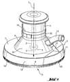
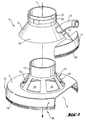
- the truncated conical outer contour 18 having top 6 is about the longitudinal direction L of the drive spindle 2 pivotable and non-displaceable in the longitudinal direction L on Housing 1 stored.
- On the outer contour 18 has an outwardly extending Exhaust nozzle 12, through which a vacuum source, not shown with the through Extraction hood 5 formed interior is connectable.
- the upper part 6 At the longitudinal direction L of the drive spindle 2 side facing away from the tool holder 4, the upper part 6 a Holding part 19 on.
- lower part 7 has a free End 3 and transversely to the longitudinal direction L of the drive spindle 2 open recess 8.
- the plane or surface spanned by the recess 8 corresponds to 0.07 times the enclosed by the free end 9 of the lower part 7, suction opening 10.
- the through the Recess 8 spanned plane extends transversely to the longitudinal direction L of the drive spindle. 2 A, for example, by a snap connection fastened to the lower part 7, cover 11 allows a closure of the recess 8 and thereby a maximum suction power.
- the cover 11 is formed substantially complementary to the recess 8.
- the lower part 7 has at the free end a dust curtain, for example a in the longitudinal direction L extending bristle rim 14, on, the free end of the lower part 7 bounded.
- the bristle rim 14 is made of an elastic material produced.
- the suction hood 5 also has an exhaust bracket 15. The one pivotable and axial mounting of the upper part 6 and the lower part 7 on the housing. 1 ensures.
- the suction holder 15 has a frustoconical cage element 16, and a side facing away from the longitudinal direction L of the tool holder 4 sides of the cage element 16 subsequent tubular-shaped holding element 17, which with the Holding part 19 of the upper part 6 cooperates.
- the lower part 7 adjoins the longitudinal direction L of the tool holder 4 facing side of the cage member 16th and is integrally formed with this.
- the lower part 7 is rotationally fixed and longitudinally L immovably mounted on the suction holder 15.
- the with recesses 24 provided cage element 16 serves to support the upper part 6 and has on the outer contour same slope up.
- the housing 1 has a tubular shape in the longitudinal direction L on the end facing the tool trained, for reasons of clarity, not shown, receiving part, which cooperates with the holding elements 17.
- a on the outer contour of the holding part 19 of the upper part 6 mounted clamping fixture 22 is the entire suction hood, in particular the upper part 6, the lower part 7 and the cage element 16 on the housing 1 Reibund / or lockable.
- the clamping attachment 22 has, for example, a Tensioning lever mechanism for releasably securing the upper part 6 and the lower part 7 am Housing 1 on.
- the cylinder-segment-shaped cover member 11 is connected by a connecting web 21, in particular an elastic connecting web 21, connected to the upper part 6. At his the free end facing the cover 11 has a dust curtain, For example, a bristle rim 23.
- the cover 11 is tubular and pivotable on the lower part. 7 and / or the cage element 16 stored. By pivoting the cover 11 against the lower part 7, the recess 8 is closed.
Landscapes
- Engineering & Computer Science (AREA)
- Mechanical Engineering (AREA)
- Grinding-Machine Dressing And Accessory Apparatuses (AREA)
- Finish Polishing, Edge Sharpening, And Grinding By Specific Grinding Devices (AREA)
- Prevention Of Fouling (AREA)
- Polishing Bodies And Polishing Tools (AREA)
- Disintegrating Or Milling (AREA)
- Carbon And Carbon Compounds (AREA)
- Shovels (AREA)
Claims (7)
- Ponceuse avec un carter (1) et une broche d'entraínement à entraínement motorisé (2), un mandrin d'outil (4) étant prévu à l'extrémité libre (3) de cette dernière dépassant du carter (1), et au carter (1) se raccordant un capot d'aspiration (5) qui entoure l'extrémité libre (3) de la broche d'entraínement (2) et est ouvert en direction du mandrin d'outil (4) et qui comporte une partie supérieure (6) et une partie inférieure (7) qui s'y raccorde et est ouverte en direction du mandrin d'outil (4), la partie inférieure (7) étant montée à rotation sur le carter (1) sensiblement autour de l'axe longitudinal (L) de la broche d'entraínement (2) et étant pourvue d'au moins un évidement (8) ouvert vers l'extrémité libre, le plan défini par l'évidement (8) s'étendant transversalement à la direction longitudinale (L) de la broche d'entraínement (2) et correspondant à 0,02 à 0,1 fois l'ouverture d'aspiration (10) entourée par l'extrémité libre (9) de la partie inférieure (7), et l'évidement (8) pouvant être fermé par une partie de recouvrement (11), caractérisée en ce que la partie de recouvrement (11) est montée à pivotement par rapport à la partie inférieure (7).
- Ponceuse selon la revendication 1, caractérisée en ce que la partie de recouvrement (11) est réalisée complémentaire de l'évidement (8).
- Ponceuse selon la revendication 1 ou 2, caractérisée en ce que sur la partie supérieure (6) est prévue une tubulure de raccordement (12) pour une source de dépression.
- Ponceuse selon une des revendications 1 à 3, caractérisée en ce que la partie de recouvrement (11) est montée rigide sur le carter (1).
- Ponceuse selon une des revendications 1 à 3, caractérisée en ce que la partie de recouvrement (11) est montée sur la partie supérieure (6).
- Ponceuse selon une des revendications 1 à 5, caractérisée en ce que la partie inférieure (7) peut pivoter par rapport à la partie supérieure (6) sensiblement autour de l'axe longitudinal (L) de la broche d'entraínement (2).
- Ponceuse selon une des revendications 1 à 6, caractérisée en ce que la partie supérieure (6) peut pivoter par rapport au carter (1) sensiblement autour de l'axe longitudinal (L) de la broche d'entraínement (2).
Priority Applications (1)
| Application Number | Priority Date | Filing Date | Title |
|---|---|---|---|
| DK02406077T DK1321228T3 (da) | 2001-12-20 | 2002-12-09 | Slibeindretning med udsugningshætte |
Applications Claiming Priority (2)
| Application Number | Priority Date | Filing Date | Title |
|---|---|---|---|
| DE10162632 | 2001-12-20 | ||
| DE10162632A DE10162632A1 (de) | 2001-12-20 | 2001-12-20 | Schleifgerät mit Absaughaube |
Publications (2)
| Publication Number | Publication Date |
|---|---|
| EP1321228A1 EP1321228A1 (fr) | 2003-06-25 |
| EP1321228B1 true EP1321228B1 (fr) | 2005-06-08 |
Family
ID=7709946
Family Applications (1)
| Application Number | Title | Priority Date | Filing Date |
|---|---|---|---|
| EP02406077A Expired - Lifetime EP1321228B1 (fr) | 2001-12-20 | 2002-12-09 | Meuleuse avec capot d'aspiration |
Country Status (8)
| Country | Link |
|---|---|
| US (1) | US6896605B2 (fr) |
| EP (1) | EP1321228B1 (fr) |
| AT (1) | ATE297289T1 (fr) |
| DE (2) | DE10162632A1 (fr) |
| DK (1) | DK1321228T3 (fr) |
| ES (1) | ES2243684T3 (fr) |
| HU (1) | HU226840B1 (fr) |
| PL (1) | PL203129B1 (fr) |
Families Citing this family (30)
| Publication number | Priority date | Publication date | Assignee | Title |
|---|---|---|---|---|
| ES2327237T3 (es) * | 2003-12-08 | 2009-10-27 | Flex Trim A/S | Pulidora. |
| USD537316S1 (en) * | 2005-11-10 | 2007-02-27 | Skradski Thomas J | Debris shield |
| USD589318S1 (en) * | 2005-11-24 | 2009-03-31 | Alfred Kaercher Gmbh & Co. Kg | Drill dust catcher |
| USD614678S1 (en) * | 2009-03-04 | 2010-04-27 | Rockler Companies, Inc. | Dust collection fitting |
| NL2002807C2 (nl) * | 2009-04-27 | 2010-10-28 | Collect Systems Europ B V | Beschermkap voor haakse slijpmachine, haakse slijpmachine. |
| US8702478B2 (en) * | 2009-05-08 | 2014-04-22 | Michael Loveless | Angle grinder dust shroud with unitary adjustable mounting collar |
| US8523637B2 (en) * | 2009-07-21 | 2013-09-03 | Dustless Depot, Llc | Angle grinder dust shroud with slideable access hatch |
| US8561512B2 (en) * | 2009-08-18 | 2013-10-22 | Dustless Depot Llc | Cutoff saw and stand with integrated dust filtration system |
| JP5323624B2 (ja) * | 2009-09-14 | 2013-10-23 | 株式会社マキタ | ディスクグラインダの集塵カバー |
| USD677292S1 (en) * | 2010-12-13 | 2013-03-05 | Dean Kevin Barnes | Debris collector for vertical drilling |
| JP2012213820A (ja) * | 2011-03-31 | 2012-11-08 | Makita Corp | 電動工具 |
| US9038275B2 (en) | 2011-09-07 | 2015-05-26 | Dustless Depot, Llc | Reciprocating saw dust shroud |
| CN103386642B (zh) * | 2012-05-09 | 2015-09-23 | 海峰机械工业股份有限公司 | 集尘式研磨机 |
| JP5998331B2 (ja) * | 2012-07-31 | 2016-09-28 | 極東産機株式会社 | 内装施工用パテ研削工具 |
| WO2016003876A1 (fr) | 2014-07-03 | 2016-01-07 | Oklahoma Medical Research Foundation | Traitement de la sclerose en plaque et de la neuromyelite optique |
| USD803916S1 (en) | 2016-07-14 | 2017-11-28 | Alfred Kaercher Gmbh & Co. Kg | Drilling dust collector |
| USD818788S1 (en) | 2016-07-14 | 2018-05-29 | Alfred Kaercher Gmbh & Co. Kg | Device for collecting drilling dust |
| US10293421B2 (en) | 2016-09-15 | 2019-05-21 | Dustless Depot, Llc | Circular saw dust collection shroud |
| USD816453S1 (en) | 2016-09-15 | 2018-05-01 | Dustless Depot, Llc | Circular saw dust shroud |
| USD818506S1 (en) * | 2017-06-26 | 2018-05-22 | Jpw Industries Inc. | Hood for drum sander |
| US10576599B2 (en) * | 2017-09-12 | 2020-03-03 | Baker Drywall IP Ltd. | Portable EPS panel rasping platform |
| US11440160B2 (en) * | 2018-03-23 | 2022-09-13 | Paul Mueller Company | Guards for use with power tools and power tools including such guards |
| US11491611B2 (en) * | 2018-08-14 | 2022-11-08 | Illinois Tool Works Inc. | Splash guards for grinder/polisher machines and grinder/polisher machines having splash guards |
| USD908149S1 (en) | 2018-10-23 | 2021-01-19 | Dustless Depot Llc | Angle grinder dust shroud with variable position slots for mounting brackets |
| US11123839B2 (en) | 2018-10-23 | 2021-09-21 | Dustless Depot Llc | Grinder dust shroud with input shaft gasket and adjustable mounting mechanism |
| US11273505B2 (en) | 2019-03-27 | 2022-03-15 | Dustless Depot, Llc | Circular saw dust collection shroud |
| EP3722051A1 (fr) * | 2019-04-08 | 2020-10-14 | Hilti Aktiengesellschaft | Capot anti-poussière pour un outil |
| USD1018619S1 (en) * | 2021-09-09 | 2024-03-19 | Thomas J . Skradski | Debris shield |
| USD1017657S1 (en) * | 2021-09-09 | 2024-03-12 | Thomas J. Skradski | Debris shield |
| USD1049188S1 (en) * | 2021-09-09 | 2024-10-29 | Thomas J. Skradski | Debris shield |
Family Cites Families (9)
| Publication number | Priority date | Publication date | Assignee | Title |
|---|---|---|---|---|
| US3256648A (en) * | 1963-07-17 | 1966-06-21 | Douglas A Rice | Particle removal device for portable power grinders and the like |
| US3673744A (en) * | 1971-02-12 | 1972-07-04 | Anders Oimoen | Portable grinder |
| US3824745A (en) * | 1972-08-21 | 1974-07-23 | A Hutchins | Suction system for abrading tool |
| DE2539762C3 (de) * | 1975-09-06 | 1978-05-18 | Hardo 2000 Hamburg Heuer | Schutz- und Absaughaube für Handschleif- und Poliermaschinen |
| JPS55112759A (en) * | 1979-02-19 | 1980-08-30 | Shibaura Eng Works Co Ltd | Disk grinder |
| JPS57211467A (en) * | 1981-06-23 | 1982-12-25 | Akira Takase | Disc grinder with polishing powder suction device |
| US4622782A (en) * | 1985-08-09 | 1986-11-18 | Roestenberg Jerome R | Sander shield |
| DE3636601A1 (de) * | 1986-10-28 | 1988-05-05 | Bosch Gmbh Robert | Schutzhaube fuer schleifmaschinen, insbesondere winkelschleifer, und dazu passende befestigungsaufnahme auf diese |
| DE19936555A1 (de) * | 1999-08-03 | 2001-02-08 | Hilti Ag | Staubschutzhaube für Oberflächenschleifgerät |
-
2001
- 2001-12-20 DE DE10162632A patent/DE10162632A1/de not_active Withdrawn
-
2002
- 2002-12-09 ES ES02406077T patent/ES2243684T3/es not_active Expired - Lifetime
- 2002-12-09 DE DE50203327T patent/DE50203327D1/de not_active Expired - Lifetime
- 2002-12-09 EP EP02406077A patent/EP1321228B1/fr not_active Expired - Lifetime
- 2002-12-09 AT AT02406077T patent/ATE297289T1/de active
- 2002-12-09 DK DK02406077T patent/DK1321228T3/da active
- 2002-12-10 US US10/315,782 patent/US6896605B2/en not_active Expired - Lifetime
- 2002-12-19 HU HU0204441A patent/HU226840B1/hu not_active IP Right Cessation
- 2002-12-19 PL PL357897A patent/PL203129B1/pl unknown
Also Published As
| Publication number | Publication date |
|---|---|
| HU0204441D0 (en) | 2003-02-28 |
| DE50203327D1 (de) | 2005-07-14 |
| ATE297289T1 (de) | 2005-06-15 |
| HUP0204441A2 (hu) | 2003-09-29 |
| DE10162632A1 (de) | 2003-07-03 |
| HU226840B1 (hu) | 2009-12-28 |
| EP1321228A1 (fr) | 2003-06-25 |
| US6896605B2 (en) | 2005-05-24 |
| PL203129B1 (pl) | 2009-08-31 |
| PL357897A1 (en) | 2003-06-30 |
| DK1321228T3 (da) | 2005-10-03 |
| HUP0204441A3 (en) | 2004-03-29 |
| ES2243684T3 (es) | 2005-12-01 |
| US20030119435A1 (en) | 2003-06-26 |
Similar Documents
| Publication | Publication Date | Title |
|---|---|---|
| EP1321228B1 (fr) | Meuleuse avec capot d'aspiration | |
| EP1116551B1 (fr) | Ponçeuse à guidage manuel | |
| DE19617572A1 (de) | Elektrische Handschleifmaschine | |
| EP2186600B1 (fr) | Dispositif de ponçage de surface, notamment un dispositif de ponçage de béton | |
| EP2163356B1 (fr) | Machine-outil manuel dotée d'un capot de recouvrement et d'un raccordement d'évacuation de poussière | |
| DE19923145A1 (de) | Absaughaube für handgeführte Trennschleifer | |
| DE10224837A1 (de) | Werkzeugmaschine | |
| DE10132951A1 (de) | Handgeführtes Arbeitsgerät | |
| DE10039777A1 (de) | Batteriegespeistes Elektrowerkzeug | |
| EP0820838A1 (fr) | Ponçeuse à plateau excentrique | |
| EP1305137A1 (fr) | Ponceuse manuelle a bande abrasive destinee a l'usinage d'objets ronds | |
| EP2163344A2 (fr) | Machine-outil manuelle dotée d'un recouvrement de bord latéral | |
| DE4032069C2 (fr) | ||
| DE3608301A1 (de) | Stichsaege mit einem von hand fuehrbaren maschinengehaeuse | |
| DE29802027U1 (de) | Motorbetriebenes Handwerkzeug | |
| DE4238245C3 (de) | Staubabsaugeinrichtung für ein als Handgerät ausgebildetes, motorisch angetriebenes Gerät | |
| DE19807439A1 (de) | Handwerkzeugmaschine, insbesondere Winkelschleifer | |
| EP0429013B1 (fr) | Meuleuse d'angle avec aspiration des poussières | |
| WO2024023223A1 (fr) | Scie circulaire portative | |
| DE29513967U1 (de) | Säge-, Schneide-, Trennvorrichtung | |
| DE3541728A1 (de) | Handhobelmaschine | |
| DE102014200511A1 (de) | Handwerkzeugmaschine mit einer Absaughaube | |
| EP1110651A2 (fr) | Scie circulaire motorisée à main | |
| DE9203823U1 (de) | Spanabhebende Werkzeugmaschine, insbesondere Stichsäge | |
| WO1995008422A1 (fr) | Appareil de meulage portatif a moteur d'avancement integre, pourvu d'un dispositif limitant la profondeur de coupe et se presentant sous forme de capot de protection |
Legal Events
| Date | Code | Title | Description |
|---|---|---|---|
| PUAI | Public reference made under article 153(3) epc to a published international application that has entered the european phase |
Free format text: ORIGINAL CODE: 0009012 |
|
| AK | Designated contracting states |
Designated state(s): AT BE BG CH CY CZ DE DK EE ES FI FR GB GR IE IT LI LU MC NL PT SE SI SK TR |
|
| AX | Request for extension of the european patent |
Extension state: AL LT LV MK RO |
|
| 17P | Request for examination filed |
Effective date: 20031229 |
|
| AKX | Designation fees paid |
Designated state(s): AT BE BG CH CY CZ DE DK EE ES FI FR GB GR IE IT LI LU MC NL PT SE SI SK TR |
|
| 17Q | First examination report despatched |
Effective date: 20040317 |
|
| GRAP | Despatch of communication of intention to grant a patent |
Free format text: ORIGINAL CODE: EPIDOSNIGR1 |
|
| GRAS | Grant fee paid |
Free format text: ORIGINAL CODE: EPIDOSNIGR3 |
|
| GRAA | (expected) grant |
Free format text: ORIGINAL CODE: 0009210 |
|
| AK | Designated contracting states |
Kind code of ref document: B1 Designated state(s): AT BE BG CH CY CZ DE DK EE ES FI FR GB GR IE IT LI LU MC NL PT SE SI SK TR |
|
| PG25 | Lapsed in a contracting state [announced via postgrant information from national office to epo] |
Ref country code: TR Free format text: LAPSE BECAUSE OF FAILURE TO SUBMIT A TRANSLATION OF THE DESCRIPTION OR TO PAY THE FEE WITHIN THE PRESCRIBED TIME-LIMIT Effective date: 20050608 Ref country code: SK Free format text: LAPSE BECAUSE OF FAILURE TO SUBMIT A TRANSLATION OF THE DESCRIPTION OR TO PAY THE FEE WITHIN THE PRESCRIBED TIME-LIMIT Effective date: 20050608 Ref country code: SI Free format text: LAPSE BECAUSE OF FAILURE TO SUBMIT A TRANSLATION OF THE DESCRIPTION OR TO PAY THE FEE WITHIN THE PRESCRIBED TIME-LIMIT Effective date: 20050608 Ref country code: IE Free format text: LAPSE BECAUSE OF FAILURE TO SUBMIT A TRANSLATION OF THE DESCRIPTION OR TO PAY THE FEE WITHIN THE PRESCRIBED TIME-LIMIT Effective date: 20050608 Ref country code: FI Free format text: LAPSE BECAUSE OF FAILURE TO SUBMIT A TRANSLATION OF THE DESCRIPTION OR TO PAY THE FEE WITHIN THE PRESCRIBED TIME-LIMIT Effective date: 20050608 Ref country code: EE Free format text: LAPSE BECAUSE OF FAILURE TO SUBMIT A TRANSLATION OF THE DESCRIPTION OR TO PAY THE FEE WITHIN THE PRESCRIBED TIME-LIMIT Effective date: 20050608 Ref country code: CZ Free format text: LAPSE BECAUSE OF FAILURE TO SUBMIT A TRANSLATION OF THE DESCRIPTION OR TO PAY THE FEE WITHIN THE PRESCRIBED TIME-LIMIT Effective date: 20050608 |
|
| REG | Reference to a national code |
Ref country code: GB Ref legal event code: FG4D Free format text: NOT ENGLISH |
|
| REG | Reference to a national code |
Ref country code: SE Ref legal event code: TRGR |
|
| REG | Reference to a national code |
Ref country code: CH Ref legal event code: EP |
|
| REF | Corresponds to: |
Ref document number: 50203327 Country of ref document: DE Date of ref document: 20050714 Kind code of ref document: P |
|
| REG | Reference to a national code |
Ref country code: IE Ref legal event code: FG4D Free format text: LANGUAGE OF EP DOCUMENT: GERMAN |
|
| GBT | Gb: translation of ep patent filed (gb section 77(6)(a)/1977) |
Effective date: 20050815 |
|
| PG25 | Lapsed in a contracting state [announced via postgrant information from national office to epo] |
Ref country code: GR Free format text: LAPSE BECAUSE OF FAILURE TO SUBMIT A TRANSLATION OF THE DESCRIPTION OR TO PAY THE FEE WITHIN THE PRESCRIBED TIME-LIMIT Effective date: 20050908 Ref country code: BG Free format text: LAPSE BECAUSE OF FAILURE TO SUBMIT A TRANSLATION OF THE DESCRIPTION OR TO PAY THE FEE WITHIN THE PRESCRIBED TIME-LIMIT Effective date: 20050908 |
|
| REG | Reference to a national code |
Ref country code: DK Ref legal event code: T3 |
|
| PG25 | Lapsed in a contracting state [announced via postgrant information from national office to epo] |
Ref country code: PT Free format text: LAPSE BECAUSE OF FAILURE TO SUBMIT A TRANSLATION OF THE DESCRIPTION OR TO PAY THE FEE WITHIN THE PRESCRIBED TIME-LIMIT Effective date: 20051114 |
|
| REG | Reference to a national code |
Ref country code: ES Ref legal event code: FG2A Ref document number: 2243684 Country of ref document: ES Kind code of ref document: T3 |
|
| PG25 | Lapsed in a contracting state [announced via postgrant information from national office to epo] |
Ref country code: CY Free format text: LAPSE BECAUSE OF FAILURE TO SUBMIT A TRANSLATION OF THE DESCRIPTION OR TO PAY THE FEE WITHIN THE PRESCRIBED TIME-LIMIT Effective date: 20051209 |
|
| PG25 | Lapsed in a contracting state [announced via postgrant information from national office to epo] |
Ref country code: MC Free format text: LAPSE BECAUSE OF NON-PAYMENT OF DUE FEES Effective date: 20051231 Ref country code: LU Free format text: LAPSE BECAUSE OF NON-PAYMENT OF DUE FEES Effective date: 20051231 |
|
| REG | Reference to a national code |
Ref country code: IE Ref legal event code: FD4D |
|
| ET | Fr: translation filed | ||
| PLBE | No opposition filed within time limit |
Free format text: ORIGINAL CODE: 0009261 |
|
| STAA | Information on the status of an ep patent application or granted ep patent |
Free format text: STATUS: NO OPPOSITION FILED WITHIN TIME LIMIT |
|
| 26N | No opposition filed |
Effective date: 20060309 |
|
| REG | Reference to a national code |
Ref country code: FR Ref legal event code: PLFP Year of fee payment: 14 |
|
| REG | Reference to a national code |
Ref country code: FR Ref legal event code: PLFP Year of fee payment: 15 |
|
| REG | Reference to a national code |
Ref country code: FR Ref legal event code: PLFP Year of fee payment: 16 |
|
| PGFP | Annual fee paid to national office [announced via postgrant information from national office to epo] |
Ref country code: SE Payment date: 20191219 Year of fee payment: 18 Ref country code: DE Payment date: 20191210 Year of fee payment: 18 Ref country code: NL Payment date: 20191219 Year of fee payment: 18 |
|
| PGFP | Annual fee paid to national office [announced via postgrant information from national office to epo] |
Ref country code: FR Payment date: 20191219 Year of fee payment: 18 Ref country code: BE Payment date: 20191219 Year of fee payment: 18 Ref country code: DK Payment date: 20191227 Year of fee payment: 18 |
|
| PGFP | Annual fee paid to national office [announced via postgrant information from national office to epo] |
Ref country code: AT Payment date: 20191220 Year of fee payment: 18 Ref country code: CH Payment date: 20191219 Year of fee payment: 18 |
|
| PGFP | Annual fee paid to national office [announced via postgrant information from national office to epo] |
Ref country code: GB Payment date: 20191220 Year of fee payment: 18 Ref country code: ES Payment date: 20200121 Year of fee payment: 18 |
|
| REG | Reference to a national code |
Ref country code: DE Ref legal event code: R119 Ref document number: 50203327 Country of ref document: DE |
|
| REG | Reference to a national code |
Ref country code: DK Ref legal event code: EBP Effective date: 20201231 |
|
| REG | Reference to a national code |
Ref country code: CH Ref legal event code: PL |
|
| REG | Reference to a national code |
Ref country code: SE Ref legal event code: EUG |
|
| REG | Reference to a national code |
Ref country code: NL Ref legal event code: MM Effective date: 20210101 |
|
| REG | Reference to a national code |
Ref country code: AT Ref legal event code: MM01 Ref document number: 297289 Country of ref document: AT Kind code of ref document: T Effective date: 20201209 |
|
| GBPC | Gb: european patent ceased through non-payment of renewal fee |
Effective date: 20201209 |
|
| REG | Reference to a national code |
Ref country code: BE Ref legal event code: MM Effective date: 20201231 |
|
| PG25 | Lapsed in a contracting state [announced via postgrant information from national office to epo] |
Ref country code: NL Free format text: LAPSE BECAUSE OF NON-PAYMENT OF DUE FEES Effective date: 20210101 |
|
| PG25 | Lapsed in a contracting state [announced via postgrant information from national office to epo] |
Ref country code: AT Free format text: LAPSE BECAUSE OF NON-PAYMENT OF DUE FEES Effective date: 20201209 Ref country code: FR Free format text: LAPSE BECAUSE OF NON-PAYMENT OF DUE FEES Effective date: 20201231 |
|
| PG25 | Lapsed in a contracting state [announced via postgrant information from national office to epo] |
Ref country code: GB Free format text: LAPSE BECAUSE OF NON-PAYMENT OF DUE FEES Effective date: 20201209 Ref country code: CH Free format text: LAPSE BECAUSE OF NON-PAYMENT OF DUE FEES Effective date: 20201231 Ref country code: DE Free format text: LAPSE BECAUSE OF NON-PAYMENT OF DUE FEES Effective date: 20210701 Ref country code: SE Free format text: LAPSE BECAUSE OF NON-PAYMENT OF DUE FEES Effective date: 20201210 Ref country code: LI Free format text: LAPSE BECAUSE OF NON-PAYMENT OF DUE FEES Effective date: 20201231 |
|
| PG25 | Lapsed in a contracting state [announced via postgrant information from national office to epo] |
Ref country code: DK Free format text: LAPSE BECAUSE OF NON-PAYMENT OF DUE FEES Effective date: 20201231 |
|
| REG | Reference to a national code |
Ref country code: ES Ref legal event code: FD2A Effective date: 20220208 |
|
| PG25 | Lapsed in a contracting state [announced via postgrant information from national office to epo] |
Ref country code: ES Free format text: LAPSE BECAUSE OF NON-PAYMENT OF DUE FEES Effective date: 20201210 |
|
| PGFP | Annual fee paid to national office [announced via postgrant information from national office to epo] |
Ref country code: IT Payment date: 20211224 Year of fee payment: 20 |
|
| PG25 | Lapsed in a contracting state [announced via postgrant information from national office to epo] |
Ref country code: BE Free format text: LAPSE BECAUSE OF NON-PAYMENT OF DUE FEES Effective date: 20201231 |
|
| P01 | Opt-out of the competence of the unified patent court (upc) registered |
Effective date: 20230322 |