EP1321568A2 - Drahtseil mit mehreren Litzen sowie Verfahren und Vorrichtung zum Einbringen einer Stützlitze - Google Patents
Drahtseil mit mehreren Litzen sowie Verfahren und Vorrichtung zum Einbringen einer Stützlitze Download PDFInfo
- Publication number
- EP1321568A2 EP1321568A2 EP02450283A EP02450283A EP1321568A2 EP 1321568 A2 EP1321568 A2 EP 1321568A2 EP 02450283 A EP02450283 A EP 02450283A EP 02450283 A EP02450283 A EP 02450283A EP 1321568 A2 EP1321568 A2 EP 1321568A2
- Authority
- EP
- European Patent Office
- Prior art keywords
- strands
- wire rope
- support
- strand
- roller
- Prior art date
- Legal status (The legal status is an assumption and is not a legal conclusion. Google has not performed a legal analysis and makes no representation as to the accuracy of the status listed.)
- Withdrawn
Links
Images

Classifications
-
- D—TEXTILES; PAPER
- D07—ROPES; CABLES OTHER THAN ELECTRIC
- D07B—ROPES OR CABLES IN GENERAL
- D07B7/00—Details of, or auxiliary devices incorporated in, rope- or cable-making machines; Auxiliary apparatus associated with such machines
- D07B7/16—Auxiliary apparatus
- D07B7/167—Auxiliary apparatus for joining rope components
-
- D—TEXTILES; PAPER
- D07—ROPES; CABLES OTHER THAN ELECTRIC
- D07B—ROPES OR CABLES IN GENERAL
- D07B7/00—Details of, or auxiliary devices incorporated in, rope- or cable-making machines; Auxiliary apparatus associated with such machines
- D07B7/16—Auxiliary apparatus
- D07B7/169—Auxiliary apparatus for interconnecting two cable or rope ends, e.g. by splicing or sewing
-
- D—TEXTILES; PAPER
- D07—ROPES; CABLES OTHER THAN ELECTRIC
- D07B—ROPES OR CABLES IN GENERAL
- D07B7/00—Details of, or auxiliary devices incorporated in, rope- or cable-making machines; Auxiliary apparatus associated with such machines
- D07B7/16—Auxiliary apparatus
- D07B7/18—Auxiliary apparatus for spreading or untwisting ropes or cables into constituent parts for treatment or splicing purposes
- D07B7/182—Auxiliary apparatus for spreading or untwisting ropes or cables into constituent parts for treatment or splicing purposes for spreading ropes or cables by hand-operated tools for splicing purposes, e.g. needles or spikes
-
- D—TEXTILES; PAPER
- D07—ROPES; CABLES OTHER THAN ELECTRIC
- D07B—ROPES OR CABLES IN GENERAL
- D07B2201/00—Ropes or cables
- D07B2201/20—Rope or cable components
- D07B2201/2047—Cores
- D07B2201/2052—Cores characterised by their structure
-
- D—TEXTILES; PAPER
- D07—ROPES; CABLES OTHER THAN ELECTRIC
- D07B—ROPES OR CABLES IN GENERAL
- D07B2201/00—Ropes or cables
- D07B2201/20—Rope or cable components
- D07B2201/2047—Cores
- D07B2201/2052—Cores characterised by their structure
- D07B2201/2055—Cores characterised by their structure comprising filaments or fibers
-
- D—TEXTILES; PAPER
- D07—ROPES; CABLES OTHER THAN ELECTRIC
- D07B—ROPES OR CABLES IN GENERAL
- D07B2201/00—Ropes or cables
- D07B2201/20—Rope or cable components
- D07B2201/2047—Cores
- D07B2201/2052—Cores characterised by their structure
- D07B2201/2059—Cores characterised by their structure comprising wires
- D07B2201/2061—Cores characterised by their structure comprising wires resulting in a twisted structure
-
- D—TEXTILES; PAPER
- D07—ROPES; CABLES OTHER THAN ELECTRIC
- D07B—ROPES OR CABLES IN GENERAL
- D07B7/00—Details of, or auxiliary devices incorporated in, rope- or cable-making machines; Auxiliary apparatus associated with such machines
- D07B7/16—Auxiliary apparatus
- D07B7/165—Auxiliary apparatus for making slings
Definitions
- the invention relates to a wire rope with several strands, wherein at least one long splice connection is provided.
- the invention relates to a method for Introducing at least one support strand in a multi-strand Wire rope.
- the invention also relates to a device for inserting at least one support strand in a multi-strand Wire rope.
- Long splice connections are used to connect the ends of rope sections interconnected, which in particular the manufacture of endless rope loops from finite rope sections for transport systems, for example cable cars, is made possible.
- long splice connection there is a reciprocal one Lay the individual strands of both rope ends into one another. The stranded wires replaced here in the area of Long splice connection previously made in this area from the wire rope removed central insert.
- This configuration creates a frictional connection that holds the rope sections together guaranteed even under the influence of high tensile forces, in particular even with wire ropes, which are in constant operation Are subjected to bending stress. As a result, it comes between the strands of the rope friction with respect to Achievable lifespan is of great importance when the wire ropes are intended for use in transport systems and in Operation run continuously over roles.
- the object of the invention is a wire rope of the beginning to create the type mentioned, in which the friction between the Strands as well as the compressive stresses at crossing points of the Strands (at the so-called splice nodes) should be kept as low as possible can and a largely uniform spacing of the strands is guaranteed becomes. This can reduce the development of wire breaks and thus an increase in the lifespan can be achieved.
- a method and a device according to the invention are intended to be created in the area of a long splice connection of the wire rope support strands on simple and quick Way to contribute.
- the wire rope of the type mentioned is according to the invention characterized in that in the area of the long splice connection at least between two neighboring strands at least a braid is provided.
- the support strands also not only secure one mutual distance between the adjacent strands of the wire rope from each other, making not only the friction of neighboring Strands against each other is avoided, but the support strands can also used as a very effective lubricant reservoir in which already during production and also later Lubricant can be easily introduced because the support strands through the internal gap between neighboring strands are accessible.
- a rope made of plastic preferably as a support strand Polyamide, which is provided, is a stable support and the Elimination of the friction between two neighboring strands guaranteed a comparatively long period.
- the method of the type mentioned is in accordance with the invention characterized in that in the area of a long splice connection at least two strands surrounding an insert strand be pushed apart, and the support strand between the apart from the strands.
- a Long splice connection support strands are introduced, this being the case can happen regardless of the number of strands of the wire rope; this also means that the rope strands are distanced in this area and achieved a reduction in the friction between them.
- the device of the type mentioned is according to the invention characterized in that at least one is rotatable mounted roller for pushing apart adjacent wire rope strands is provided in the area of a long splice connection, between which the support strand is inserted, the role has a groove for guiding the support wire to be inserted.
- the support strands in the long splice area of the multi-strand It is advantageous to use a wire rope if several support strands at the same time are introduced and accordingly several roles are provided, where the number of roles the number of to be brought in simultaneously Support strands corresponds.
- the number of roles corresponds to as already in connection with the above-mentioned procedure performed on a wire rope with an even number of strands advantageously half of the total number of wire rope strands, because on the one hand there is a dodge of the wire rope strands is possible to release an insertion gap and on the other hand the whole of the support strands only in two work steps can be introduced.
- the role (s) in each case is (are) stored in a U-shaped receiving device, which is attached to a threaded spindle.
- About the setting of the Threaded spindle can thus be transferred to their roles Insertion position approximated to the wire rope and after the end of the insertion process can be removed from the wire rope again. moreover can adapt to different wire rope diameters respectively.
- rollers are arranged on a support ring, results a structurally simple functional arrangement of the rollers, where the support ring is divided and a hinge connection can be closable in the area of a long splice connection wire rope to be provided with support strands in the interior of the Insert the support ring and then quickly and securely close it to be able to.
- each roll can be inserted the braid independent of the other roles with the braid be supplied. There is also easy guidance the support wire to be inserted from the supply spool to the roll.
- the entire device is used to insert the support strands moved along the wire rope, causing the reels to be two adjacent Strands in the area where the support strand is inserted will push apart. These wire rope strands spring as the roll continues to move back to its original position back, causing the support strands in the rope assembly be included.
- the entire device is preferred manually moved forward and at the same time the spiral following wound strands rotated around the rope circumference. An unwanted one Reliably loosen the device from the wire rope prevent it is beneficial if a support to secure the Device is provided on the wire rope.
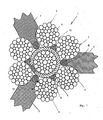
- FIG. 1 shows a wire rope 1 with six strands 2, which in turn is also composed of several strands 3 are.
- the cross section shown in Fig. 1 shows the area of a Long splice connection, in which instead of a central insert or core of the wire rope 1 an insertion strand 4 of a to be connected Wire rope or section is provided.
- the insert strands 4 is with a polyamide rope 5 to achieve a stable Wrapped in sheathing.
- rollers 3 each have a narrow end region 8 in which a groove 9 is provided for receiving the support strand 6 is.
- Starting from the narrow end area 8 are on both sides concave cross-sectional enlargements 10 - preferably in Circular arc shape with a radius approximately equal to that of the strands 2 - provided, resulting in an adaptation to the cylindrical Shape of the strands 2 and thus a space-saving recording of Wire rope strands 2 in the rolls 7 results.
- the forehead area 8 protrudes as far from Fig. 1 in the working position the wrapped stranded wire 4 that just space for the Support wire 6 remains.
- a six-strand wire rope 1 is shown, wherein three support strands 6 already used in a first operation were and in a second operation on the roles 7 the additional support strands 6 are introduced, so that between each two adjacent wire rope strands 2 each have a support strand 6 is arranged.
- the braids 6 result in a uniform distance between the strands 2, and the compressive stresses at the crossing points of the strands 2 (splice knot not shown) are reduced. This also reduces the development of wire breaks and thus increases the life of the wire rope 1.
- the device 12 for introducing Support strands 6 in a wire rope 1 in the area of a long splice connection shown.
- the device 12 has a split Support ring 13 on a hinge 14 for inserting the Wire rope 1 can be opened; can via a closure 15 the two parts of the support ring 13 are connected to one another.
- the rollers 7 are in U-shaped or fork-shaped receiving devices 16 rotatably mounted on a perpendicular to the Axis 1 'of the wire rope 1 arranged spindle drive 17 attached are.
- the position of the Rollers 7 can be set in the radial direction of the support ring 13.
- the spindle drive 17 is accommodated in a housing 19, whereby the rollers 7 with their axes of rotation in adjustment the lay angle of the strands 2 of the wire rope 1 can be adjusted can.
- the polyamide support strands 6 to be inserted are on supply spools 20 wound up, one supply spool 20 each Role 7 is assigned.
- the wound on the supply spools 20 Support strands 6 are inserted into the groove 9 via two guides 10 out of the roller 7 and introduced into the strand gap via this groove 9.
- Supply spools 20 by means of a supply spool 10 from the outside acting spiral spring 21 braked.
- the braking force of the springs 21 can be set using nuts 22, for example.
- other means for Applying pressure - and thus for braking the supply spools 20 - may be provided as spiral springs 21, such as a stiff one Storage.
- the entire device 12 becomes Insert the support strands 6 manually moved forward and at the same time following the spirally wound wire rope strands 2 the rope circumference rotated.
- the device 12 is also a Support 23, which is a sleeve 24 encompassing the wire rope 1 has, secured to the wire rope 1.
Landscapes
- Ropes Or Cables (AREA)
- Lift-Guide Devices, And Elevator Ropes And Cables (AREA)
Abstract
Description
Claims (18)
- Drahtseil (1) mit mehreren Litzen (2), wobei zumindest eine Langspleißverbindung vorgesehen ist, dadurch gekennzeichnet, dass im Bereich der Langspleißverbindung zumindest zwischen zwei benachbarten Litzen (2) mindestens eine Stützlitze (6) vorgesehen ist.
- Drahtseil nach Anspruch 1, dadurch gekennzeichnet, dass zwischen allen eine im Bereich der Langspleißverbindung eine mittige Einlage ersetzende Einlegelitze (4) umgebenden Litzen (2) mindestens eine Stützlitze (6) vorgesehen ist.
- Drahtseil nach Anspruch 1, dadurch gekennzeichnet, dass als Stützlitze (6) ein Seil aus Kunststoff, vorzugsweise Polyamid, vorgesehen ist.
- Verfahren zum Einbringen zumindest einer Stützlitze (6) in einem mehrlitzigen Drahtseil (1), dadurch gekennzeichnet, dass im Bereich einer Langspleißverbindung zumindest zwei eine Einlegelitze (4) umgebende Litzen (2) auseinander gedrückt werden, und die Stützlitze (6) zwischen den auseinander gedrückten Litzen (2) eingefügt wird.
- Verfahren nach Anspruch 4, dadurch gekennzeichnet, dass mehrere Stützlitzen (6) zugleich eingesetzt werden.
- Verfahren nach Anspruch 5, dadurch gekennzeichnet, dass die Hälfte der Gesamtzahl der Stützlitzen (6) zugleich eingesetzt wird.
- Vorrichtung zum Einbringen zumindest einer Stützlitze (6) in einem mehrlitzigen Drahtseil (1), dadurch gekennzeichnet, dass zumindest eine drehbar gelagerte Rolle (7) zum Auseinanderdrücken von benachbarten Drahtseil-Litzen (2) im Bereich einer Langspleißverbindung vorgesehen ist, zwischen denen die Stützlitze (6) eingesetzt wird, wobei die Rolle (7) zur Führung der einzubringenden Stützlitze (6) eine Nut (9) aufweist.
- Vorrichtung nach Anspruch 7, dadurch gekennzeichnet, dass die Anzahl der Rollen (7) der Anzahl der zugleich einzubringenden Stützlitzen (6) entspricht.
- Vorrichtung nach Anspruch 7 oder 8, dadurch gekennzeichnet, dass sich die bzw. jede Rolle (7) ausgehend von einem die mittige Nut (9) enthaltenden schmalen Stirnbereich (8) auf beiden Seiten hievon entsprechend einem konkaven Profil (10) erweitert.
- Vorrichtung nach einem der Ansprüche 7 bis 9, dadurch gekennzeichnet, dass die bzw. jede Rolle (7) in einer senkrecht zur Achse (1') des Drahtseils (1) angeordneten Ebene gelagert ist.
- Vorrichtung nach einem der Ansprüche 7 bis 9, dadurch gekennzeichnet, dass die bzw. jede Rolle (7) in einer U-förmigen Aufnahmevorrichtung (16) gelagert ist, die an einer Gewindespindel (17) befestigt ist.
- Vorrichtung nach einem der Ansprüche 7 bis 11, dadurch gekennzeichnet, dass die Ausrichtung der Drehachse der bzw. jeder Rolle (7) zur Anpassung an den Schlagwinkel des Drahtseils (1) relativ zur Seilachse (1') einstellbar ist.
- Vorrichtung nach einem der Ansprüche 7 bis 11, dadurch gekennzeichnet, dass mehrere Rollen (7), in Achsrichtung des Drahtseils (1) gesehen, in Umfangsrichtung gleichmäßig um das Drahtseil (1) angeordnet sind.
- Vorrichtung nach einem der Ansprüche 7 bis 13, dadurch gekennzeichnet, dass die Rollen (7) an einem Tragring (13) angeordnet sind.
- Vorrichtung nach Anspruch 14, dadurch gekennzeichnet, dass der Tragring (13) geteilt und über eine Scharnierverbindung (14) schließbar ist.
- Vorrichtung nach Anspruch 14 oder 15, dadurch gekennzeichnet, dass auf dem Tragring (13) entsprechend der Anzahl der Rollen (7) Vorratsspulen (20) drehbar gelagert sind, auf denen die einzubringenden Stützlitzen (6) aufgewickelt sind.
- Vorrichtung nach Anspruch 16, dadurch gekennzeichnet, dass den Vorratsspulen (20) eine einstellbare Bremse (21, 22) zugeordnet ist.
- Vorrichtung nach einem der Ansprüche 7 bis 17, gekennzeichnet durch eine Stütze (23) zur Sicherung der Vorrichtung (12) an dem Drahtseil (1).
Applications Claiming Priority (2)
| Application Number | Priority Date | Filing Date | Title |
|---|---|---|---|
| AT0096701U AT5699U1 (de) | 2001-12-20 | 2001-12-20 | Drahtseil mit mehreren litzen sowie verfahren und vorrichtung zum einbringen einer stützlitze |
| AT9672001U | 2001-12-20 |
Publications (2)
| Publication Number | Publication Date |
|---|---|
| EP1321568A2 true EP1321568A2 (de) | 2003-06-25 |
| EP1321568A3 EP1321568A3 (de) | 2004-11-24 |
Family
ID=3503912
Family Applications (1)
| Application Number | Title | Priority Date | Filing Date |
|---|---|---|---|
| EP02450283A Withdrawn EP1321568A3 (de) | 2001-12-20 | 2002-12-17 | Drahtseil mit mehreren Litzen sowie Verfahren und Vorrichtung zum Einbringen einer Stützlitze |
Country Status (2)
| Country | Link |
|---|---|
| EP (1) | EP1321568A3 (de) |
| AT (1) | AT5699U1 (de) |
Cited By (5)
| Publication number | Priority date | Publication date | Assignee | Title |
|---|---|---|---|---|
| EP2514867A2 (de) | 2011-04-21 | 2012-10-24 | Teufelberger Seil Gesellschaft m.b.H. | Drahtseil mit einer Langspleißverbindung |
| CN107476100A (zh) * | 2017-08-21 | 2017-12-15 | 长治高测新材料科技有限公司 | 环形钢丝绳的制造装置 |
| JP2020501033A (ja) * | 2016-11-28 | 2020-01-16 | ヴォッベン プロパティーズ ゲーエムベーハーWobben Properties Gmbh | 引張ワイヤ拡開装置、引張ワイヤ潤滑装置および引張ワイヤケーブル潤滑方法 |
| CN112483152A (zh) * | 2020-11-23 | 2021-03-12 | 山东焱鑫矿用材料加工有限公司 | 一种新型全长粘固锚索 |
| CN118880640A (zh) * | 2024-09-29 | 2024-11-01 | 宁波凯特机械有限公司 | 一种三角股钢丝绳成型系统 |
Families Citing this family (1)
| Publication number | Priority date | Publication date | Assignee | Title |
|---|---|---|---|---|
| JP6368449B1 (ja) | 2017-12-26 | 2018-08-01 | 理研興業株式会社 | 樹脂線付きワイヤロープ、樹脂線巻付型及び樹脂線付きワイヤロープの製造方法 |
Family Cites Families (7)
| Publication number | Priority date | Publication date | Assignee | Title |
|---|---|---|---|---|
| US2019519A (en) * | 1933-08-23 | 1935-11-05 | Wood Henry Allyn | Method of and machine for altering a steel rope |
| US2019520A (en) * | 1934-05-15 | 1935-11-05 | Wood Henry Allyn | Method and means for joining individual wires in two ropes to make a single rope |
| GB2011969B (en) * | 1977-11-11 | 1982-04-07 | Cable Belt Ltd | Ropes and the like |
| DE3237733A1 (de) * | 1982-10-12 | 1984-04-12 | Drahtseilwerk Saar GmbH, 6654 Kirkel | Verfahren zum herstellen eines zusammengesetzten drahtseils |
| AT407761B (de) * | 1989-10-31 | 2001-06-25 | Teufelberger Seil Ges M B H | Drahtseil |
| FR2724398B1 (fr) * | 1994-09-08 | 1997-01-24 | Pomagalski Sa | Cable d'une installation de transport |
| AT3186U1 (de) * | 1998-11-05 | 1999-11-25 | Teufelberger Seil Gmbh | Hüllenfreies förderseil für seilbahnen oder stadtbahnen |
-
2001
- 2001-12-20 AT AT0096701U patent/AT5699U1/de not_active IP Right Cessation
-
2002
- 2002-12-17 EP EP02450283A patent/EP1321568A3/de not_active Withdrawn
Cited By (9)
| Publication number | Priority date | Publication date | Assignee | Title |
|---|---|---|---|---|
| EP2514867A2 (de) | 2011-04-21 | 2012-10-24 | Teufelberger Seil Gesellschaft m.b.H. | Drahtseil mit einer Langspleißverbindung |
| EP2514867A3 (de) * | 2011-04-21 | 2013-03-06 | Teufelberger Seil Gesellschaft m.b.H. | Drahtseil mit einer Langspleißverbindung |
| JP2020501033A (ja) * | 2016-11-28 | 2020-01-16 | ヴォッベン プロパティーズ ゲーエムベーハーWobben Properties Gmbh | 引張ワイヤ拡開装置、引張ワイヤ潤滑装置および引張ワイヤケーブル潤滑方法 |
| US11248341B2 (en) | 2016-11-28 | 2022-02-15 | Wobben Properties Gmbh | Tensioning cable spreading device and tensioning cable lubrication device and method |
| CN107476100A (zh) * | 2017-08-21 | 2017-12-15 | 长治高测新材料科技有限公司 | 环形钢丝绳的制造装置 |
| CN107476100B (zh) * | 2017-08-21 | 2023-12-05 | 长治高测新材料科技有限公司 | 环形钢丝绳的制造装置 |
| CN112483152A (zh) * | 2020-11-23 | 2021-03-12 | 山东焱鑫矿用材料加工有限公司 | 一种新型全长粘固锚索 |
| CN112483152B (zh) * | 2020-11-23 | 2025-09-02 | 山东焱鑫矿用材料加工有限公司 | 一种新型全长粘固锚索及其使用方法 |
| CN118880640A (zh) * | 2024-09-29 | 2024-11-01 | 宁波凯特机械有限公司 | 一种三角股钢丝绳成型系统 |
Also Published As
| Publication number | Publication date |
|---|---|
| EP1321568A3 (de) | 2004-11-24 |
| AT5699U1 (de) | 2002-10-25 |
Similar Documents
| Publication | Publication Date | Title |
|---|---|---|
| DE69318291T2 (de) | Verfahren und einrichtung zur herstellung eines verbindungskabels | |
| DE202016102087U1 (de) | Leitungsführungssystem für mindestens eine auf- und abspulbare Versorgungsleitung sowie Drehführung hierfür | |
| DE1685829B2 (de) | Paralleldrahtbündel und Vorrichtung zu seiner Herstellung | |
| DE69733053T2 (de) | Herstellungsverfahren eines optischen Kabels mit SZ-Führungsnuten | |
| EP1145739A2 (de) | Bestrahlungsgerät | |
| EP1997762A2 (de) | Vorrichtung zum Auf- und Abwickeln von strangartigem Wickelgut | |
| DE2340833A1 (de) | Verfahren und vorrichtung zum aufbringen von bewehrungsband auf einen laenglichen kern, insbesondere auf eine kabelseele | |
| EP1321568A2 (de) | Drahtseil mit mehreren Litzen sowie Verfahren und Vorrichtung zum Einbringen einer Stützlitze | |
| DE2455154A1 (de) | Geraet zum verarbeiten von faeden | |
| DE2734398A1 (de) | Vorrichtung zur herstellung von kabeln aus kabelverseilelementen | |
| DE69410537T2 (de) | Verfahren zum Wickeln einer Spule und Zusammensetzung einer Spulenwickelmaschine zur Durchführung des Verfahrens | |
| DE2243718A1 (de) | Verfahren und vorrichtung zum aufwickeln einer vielzahl von draehten auf eine schlauchkarkasse | |
| DE3916740A1 (de) | Textilmaschine mit verstellbarer anpresswalzenanordnung | |
| EP2514867B1 (de) | Drahtseil mit einer Langspleißverbindung | |
| EP3775367B1 (de) | Verlitzmaschine | |
| DE102004037672A1 (de) | Drahtzuführungsverfahren und Vorrichtung zur Durchführung des Verfahrens | |
| EP0842716A2 (de) | Verfahren und Vorrichtung zur Herstellung von Metallröhrchen grosser Länge | |
| EP2223752B1 (de) | Werkzeugbausatz zum Ausbilden von an einer Werkzeugeinheit einer Biegemaschine ankoppelbaren Biegewerkzeugen zum Biegen oder Wickeln strangförmiger Werkstücke | |
| DE4424173A1 (de) | Einrichtung und Verfahren zum Fördern eines langgestreckten Gutes | |
| DE737307C (de) | Fuehrungsvorrichtung zum Aufwickeln von Faeden, Draehten, Kabeln, Ketten o. dgl. auf umlaufende Spulen oder Trommeln | |
| DE102016224176B3 (de) | Vorrichtung und Verfahren zum Abwickeln eines Materials von einer Vorratstrommel | |
| DE2201548C3 (de) | Seilwinde für unbegrenzten Seildurchlauf | |
| EP3715512B1 (de) | Kettbaumanordnung | |
| DE3736857A1 (de) | Aufwickeldorn fuer ein blechband | |
| DE2700218C3 (de) | Schlauchtrommel einer Flüssigkeitskühleinrichtung eines Walzwerkes zum Herstellen von Rohren |
Legal Events
| Date | Code | Title | Description |
|---|---|---|---|
| PUAI | Public reference made under article 153(3) epc to a published international application that has entered the european phase |
Free format text: ORIGINAL CODE: 0009012 |
|
| AK | Designated contracting states |
Designated state(s): AT BE BG CH CY CZ DE DK EE ES FI FR GB GR IE IT LI LU MC NL PT SE SI SK TR |
|
| AX | Request for extension of the european patent |
Extension state: AL LT LV MK RO |
|
| PUAL | Search report despatched |
Free format text: ORIGINAL CODE: 0009013 |
|
| AK | Designated contracting states |
Kind code of ref document: A3 Designated state(s): AT BE BG CH CY CZ DE DK EE ES FI FR GB GR IE IT LI LU MC NL PT SE SI SK TR |
|
| AX | Request for extension of the european patent |
Extension state: AL LT LV MK RO |
|
| AKX | Designation fees paid | ||
| REG | Reference to a national code |
Ref country code: DE Ref legal event code: 8566 |
|
| STAA | Information on the status of an ep patent application or granted ep patent |
Free format text: STATUS: THE APPLICATION IS DEEMED TO BE WITHDRAWN |
|
| 18D | Application deemed to be withdrawn |
Effective date: 20050101 |
|
| RIN1 | Information on inventor provided before grant (corrected) |
Inventor name: RATHWALLNER, ADOLF Inventor name: GRECHHAMMER, FRIEDRICH |