EP1323857A2 - Three-dimensional non-woven fabric, mold and method used therefore - Google Patents
Three-dimensional non-woven fabric, mold and method used therefore Download PDFInfo
- Publication number
- EP1323857A2 EP1323857A2 EP02027682A EP02027682A EP1323857A2 EP 1323857 A2 EP1323857 A2 EP 1323857A2 EP 02027682 A EP02027682 A EP 02027682A EP 02027682 A EP02027682 A EP 02027682A EP 1323857 A2 EP1323857 A2 EP 1323857A2
- Authority
- EP
- European Patent Office
- Prior art keywords
- mold
- mold piece
- piece
- woven fabric
- dimensional non
- Prior art date
- Legal status (The legal status is an assumption and is not a legal conclusion. Google has not performed a legal analysis and makes no representation as to the accuracy of the status listed.)
- Withdrawn
Links
Images


Classifications
-
- D—TEXTILES; PAPER
- D04—BRAIDING; LACE-MAKING; KNITTING; TRIMMINGS; NON-WOVEN FABRICS
- D04H—MAKING TEXTILE FABRICS, e.g. FROM FIBRES OR FILAMENTARY MATERIAL; FABRICS MADE BY SUCH PROCESSES OR APPARATUS, e.g. FELTS, NON-WOVEN FABRICS; COTTON-WOOL; WADDING ; NON-WOVEN FABRICS FROM STAPLE FIBRES, FILAMENTS OR YARNS, BONDED WITH AT LEAST ONE WEB-LIKE MATERIAL DURING THEIR CONSOLIDATION
- D04H3/00—Non-woven fabrics formed wholly or mainly of yarns or like filamentary material of substantial length
- D04H3/02—Non-woven fabrics formed wholly or mainly of yarns or like filamentary material of substantial length characterised by the method of forming fleeces or layers, e.g. reorientation of yarns or filaments
-
- D—TEXTILES; PAPER
- D04—BRAIDING; LACE-MAKING; KNITTING; TRIMMINGS; NON-WOVEN FABRICS
- D04H—MAKING TEXTILE FABRICS, e.g. FROM FIBRES OR FILAMENTARY MATERIAL; FABRICS MADE BY SUCH PROCESSES OR APPARATUS, e.g. FELTS, NON-WOVEN FABRICS; COTTON-WOOL; WADDING ; NON-WOVEN FABRICS FROM STAPLE FIBRES, FILAMENTS OR YARNS, BONDED WITH AT LEAST ONE WEB-LIKE MATERIAL DURING THEIR CONSOLIDATION
- D04H3/00—Non-woven fabrics formed wholly or mainly of yarns or like filamentary material of substantial length
- D04H3/02—Non-woven fabrics formed wholly or mainly of yarns or like filamentary material of substantial length characterised by the method of forming fleeces or layers, e.g. reorientation of yarns or filaments
- D04H3/07—Non-woven fabrics formed wholly or mainly of yarns or like filamentary material of substantial length characterised by the method of forming fleeces or layers, e.g. reorientation of yarns or filaments otherwise than in a plane, e.g. in a tubular way
Definitions
- the invention relates to a method for manufacturing a three-dimensional non-woven fabric in which semi-molten fibers are spun on a mold to form the three-dimensional non-woven fabric, a mold used for the method, and the three-dimensional non-woven fabric manufactured using the method and the mold.
- a manufacturing apparatus 90 for the three-dimensional non-woven fabric includes a chain conveyor 91.
- a plurality of molds 94 arranged in a moving direction is fitted on the conveyor 91.
- Each of the molds 94 is manufactured in accordance with a shape of the three-dimensional non-woven fabric.
- a spinning nozzle 96 for spinning semi-molten fibers F is provided above the chain conveyor 91, and a spray gun 97 for spraying a binder or the like for binding each of the fibers F and a heating furnance 98 for drying the fibers are provided downstream of the spinning nozzle 96.
- the fibers F When a certain amount of the fibers F is spun out of the spinning nozzle 96 with the chain conveyor 91 driven at a constant speed, the fibers F are stacked on a forming surface 94f of the mold 94 at a constant thickness. Then, the binder is sprayed on the stacked fibers F and the fibers F are dried with the binder in the heating furnance 98, whereby each of the stacked fibers F are bonded with to form the three-dimensional non-woven fabric FC in a product shape. The three-dimensional non-woven fabric FC is removed from the forming surface 94f of the mold 94, and developed into a product after an unnecessary portion is removed.
- a first aspect of the invention relates to a method for manufacturing a three-dimensional non-woven fabric in which semi-molten fibers are spun on a forming surface of a mold, and are formed into the three-dimensional non-woven fabric.
- the method includes the steps of preparing at least two mold pieces including a first mold piece, and a second mold piece which can be mutually overlapped with the first mold piece and whose area mutually overlapping with the first mold piece is adjustable, and forming a mold including a forming surface in an desired size by partly mutually overlapping the first mold piece with the second mold piece and adjusting the area in which the two mold pieces are mutually overlapped.
- the size of the forming surface of the mold can be changed by changing the area in which the first mold piece and the second mold piece, which constitute the mold, are mutually overlapped. That is, plural types of three-dimensional non-woven fabrics whose sizes are different can be formed using only one unit of mold. This results in a cost reduction in the molds when plural types of three-dimensional non-woven fabrics are formed.
- the area in which the two mold pieces are mutually overlapped may be adjusted by sliding the first mold piece with respect to the second mold piece.
- the area in which the two mold pieces are mutually overlapped may be adjusted by changing the number of portions in which a plurality of concave portions formed on the first mold piece are fitted to a plurality of convex portions formed on the second mold piece. This makes it easy to adjust the area in which the two mold pieces are mutually overlapped.
- the three-dimensional non-woven fabric includes a main portion and a peripheral portion which is provided on a periphery of the main portion, the concave portions and the convex portions may be provided on the forming surface of the mold which forms the main portion.
- a second aspect of the invention relates to a mold which is used for a method for manufacturing a three-dimensional non-woven fabric in which semi-molten fibers are spun on a forming surface of a mold to form the three-dimensional non-woven fabric.
- This mold includes at least a first mold piece, and a second mold piece which can be mutually overlapped with the first mold piece and whose area mutually overlapping with the first mold piece is adjustable.
- At least one of the first mold piece and the second mold piece may be formed by press molding or injection molding with resin or formed from a non-woven fabric.
- the three-dimensional non-woven fabric manufactured using the method according to the first aspect and the mold according to the second aspect is included in the scope of the invention.
- a method for manufacturing a three-dimensional non-woven fabric according to an embodiment of the invention will be explained with reference to FIGS. 1A to 5B.
- the embodiment relates to a method for manufacturing a filter as an example of the three-dimensional non-woven fabric.
- a width direction of the manufacturing equipment is referred to as an X direction
- a longitudinal direction thereof is referred to as a Y direction
- an altitudinal direction thereof is referred to as a Z direction.
- manufacturing equipment 1 for the filter includes a level conveyor 2, and a plurality of molds 10 (only one unit is shown in FIG. 5A) for forming the filter is arranged on the conveyor 2 in orderly manner.
- a spinning nozzle 4 is provided at a predetermined position above the conveyor 2.
- the spinning nozzle 4 is a nozzle which employs, for example, a melt blow method, and spins fiber type resin F (hereinafter referred to as fibers F) injected from an extruder (not shown) onto the whole mold 10 in which a right mold piece 12 and a left mold piece 17 are mutually overlapped.
- the fibers F spun out of the spinning nozzle 4 are semi-molten.
- the fibers F are stacked on the forming surface or the like of the mold 10, whereby the fibers F are bonded together to form the non-woven fabric.
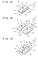
- the mold 10 for forming the filter is formed by mutually overlapping the right mold piece 12 and a left mold piece 15.
- the right mold piece 12 includes a square frame portion 13 with a constant width.
- a right mold main portion 14 is formed inside the square frame portion 13.
- the right mold main portion 14 includes a bellows portion 14w having a shape formed by sequentially arranging triangular ridges with substantially triangular side surfaces, and triangular side plate portions 14s which block right end surfaces of the bellows portion 14w. Note that left end portions 14c of the bellows portion 14w are open.
- the left mold piece 15 includes an edge portion 16 formed to have a plane U-shape with a constant width.
- a left mold main portion 17 is formed inside the edge portion 16.
- the left mold main portion 17 also includes a bellows portion 17w having a shape formed by sequentially arranging triangular ridges with substantially triangular side surfaces, and triangular side plate portions 17s which block left end surfaces of the bellows portion 17w. Note that right end portions 17c of the bellows portion 17w are open.
- crest portions of the bellows portion 14w seen from a direction opposite to the Z direction can be regarded as convex portions of the invention, and trough portions of the bellows portion 17w seen from the Z direction can be regarded as concave portions of the invention.
- the mold 10 for forming the filter is formed into the same shape as an desired shape of the filter by overlapping the right mold main portion 14 and the square frame portion 13 of the right mold piece 12 with the left mold main portion 17 and the edge portion 16 of the left mold piece 15, respectively.
- the left mold main portion 17 of the left mold piece 15 and the right mold main portion 14 of the right mold piece 12 function as forming surfaces for forming a filtration portion of the filter.
- the edge portion 16 of the left mold piece 15 and the square frame portion 13 of the right mold piece 12 function as the forming surfaces for forming a peripheral portion of the filter.
- the left mold main portion 17 of the left mold piece 15 and the right mold main portion 14 of the right mold piece 12 are referred to as first forming surfaces 14, 17, and the edge portion 16 of the left mold piece 15 and the square frame portion 13 of the right mold piece 12 are referred to as second forming surfaces 13, 16.
- the filtration portion of the filter can be regarded as a main portion of a three-dimensional non-woven fabric of the invention.
- the peripheral portion of the filter can be regarded as a peripheral portion of a three-dimensional non-woven fabric of the invention.
- Both of the mold pieces 12, 15 are configured to be relatively slidable in the width direction (X direction) with the right mold piece 12 mutually overlapped with the left mold piece 15. Therefore, as shown in FIG. 1A, widths of the forming surfaces 13, 14, 16, 17 of the mold 10 can be narrowed by increasing the area in which the right mold piece 12 is mutually overlapped with the left mold piece 15. Also, as shown in FIG. 1C, the widths of the forming surfaces 13, 14, 16, 17 of the mold 10 can be widen by reducing the area in which the right mold piece 12 is mutually overlapped with the left mold piece 15.
- the square frame portion 13 of the right piece 12 is fastened to the edge portion 16 of the left mold piece 15 with a clip or the like (not shown) so that they are retained firmly. As a result, displacement between the right piece 12 and the left mold piece 15 is prevented.
- the mold 10 is formed from, for example, a wire net, a resin net or the like which has an air permeability. Then, when the mold 10 is formed from a resin net or the like, a mold-releasing agent is applied to the mold 10 in order to prevent the fibers F from adhering to the mold 10.
- bellows portions 14w, 17w having four triangular ridges are exemplified in FIGS. 1A to 1C for the purpose of simplification of the figures.
- the actual number of the triangular ridges can be set at any value.
- the right mold piece 12 and the left mold piece 15 of the mold 10 are relatively slid in the width direction (X direction), and width dimensions of the forming surfaces 13, 14, 16, 17 of the mold 10 are adjusted to an desired width dimension of the filter. Then, the square frame portion 13 of the right mold piece 12 is fastened to the edge portion 16 of the left mold piece 15 with a clip or the like to be retained firmly to prevent displacement between the right piece 12 and the left mold piece 15.
- each of the molds 10 is set on the conveyor 2. Then, an approximately constant amount per unit of time of the fibers F is spun out of the spinning nozzle 4, and the conveyor 2 is driven at a constant speed. Thus, the mold 10 moves below the spinning nozzle 4 at a constant speed. Then, as shown in FIG. 5B, semi-molten fibers F are stacked on the first forming surfaces 14, 17 and the second forming surfaces 13, 16 of the mold 10 at an approximately constant thickness sequentially starting from an end side (left end in the figure) in the Y direction.
- the fibers F stacked on the first forming surfaces 14, 17 of the mold 10 and the fibers F stacked on the second forming surfaces 13, 16 of the mold 10 are fusion bonded with each other to form the non-woven fabric. Then, the non-woven fabric formed from the fibers F stacked on the first forming surfaces 14, 17 constitute the filtration portion of the filter. Also, the non-woven fabric formed from the fibers F stacked on the second forming surfaces 13, 16 constitute the peripheral portion of the filter.
- the filter is formed in the above-mentioned manner, a clip or the like is removed, and the right mold piece 12 of the mold 10 is moved with respect to the left mold piece 15 in a direction of narrowing the width of the mold 10. In this state, the filter is removed from the mold 10. The filter removed from the mold 10 is completed after an unnecessary portion thereof is removed.
- the mold 10 including the forming surfaces 13, 14, 16, 17 in a certain size is formed by partly overlapping a pair of the mold pieces 12, 15 and adjusting the area in which the mold pieces are mutually overlapped. Therefore, the width dimension of the forming surfaces 13, 14, 16, 17 of the mold 10 can be changed by changing the area in which the pair of mold pieces 12, 15 constituting the mold 10 are mutually overlapped. That is, plural types of filters whose width dimensions are different can be formed using only one unit of mold 10. This results in a cost reduction in the molds when plural types of filters are formed.
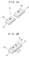
- a linear dimension of a forming surface of a mold 20 can be changed by changing the number of the triangular ridges of a bellows portion 22w of a front mold piece 22 fitted to the triangular ridges of a bellows portion 25w of an end mold piece 25, as shown in FIG. 2B.
- the width dimension and the linear dimension of forming surface of a mold 30 can be changed by constructing the mold 30 using four mold pieces 31, 32, 33, 34, which are arranged in a longitudinal direction and a lateral direction.
- the area in which the right mold piece 12 is overlapped with the left mold piece 15 may be easily adjusted by providing a convex portion on a top surface along the X direction of the square frame portion 13 of the right mold piece 12 and also providing a concave portion on a bottom surface along the X direction of the edge portion 16 of the left mold piece 15.
- filters in the same size can be manufactured without measuring the area (length) in which the right mold piece 12 is overlapped with the left mold piece 15 each time the filter is manufactured.
- FIGS 4A and 4B show modified examples of the mold 10 or the like.
- a mold 40 shown in FIG. 4B includes a first mold piece 41 and a second mold piece 42, which are in the same shape.
- the first mold piece 41 includes a square flat plate portion 41f and a plurality of convex portions 41t formed on a surface of the flat plate portion 41f.
- the convex portion 41t is formed in a frustum container shape whose bottom portion is open.
- An opening of the convex portion 41t (not shown) is formed on a rear surface of the flat plate portion 41f.
- a thickness of the convex portion 41t is formed to be substantially equal to the thickness of the flat plate portion 41f.
- the convex portions 41t are arranged at certain intervals in a longitudinal direction and a lateral direction in the first mold piece 41. Note that since the second mold piece 42 is in the same shape as the first mold piece 41, explanation thereof will be omitted.
- the first mold piece 41 and the second mold piece 42 are manufactured by pressing a steel plate or the like into shape or injection molding with resin.
- the first mold piece 41 and the second mold piece 42 may be formed from the non-woven fabric.
- the mold 40 is formed by fitting a part of the convex portion 41t of the first mold piece 41 into the inside (concave portion) of the convex portion 42t of the second mold piece 42. Therefore, the area in which the first mold piece 41 is overlapped with the second mold piece 42 may be changed by changing the number of the portions where the convex portions 41t of the first mold piece 41 are fitted in the concave portions of the second mold piece 42.
- first mold piece 41 and the second mold piece 42 in the longitudinal direction and mutually overlapping each of the end portions along the Y direction is shown in FIG. 4B, it is also possible to arrange the first mold piece 41 and the second mold piece 42 in the lateral direction and mutually overlap each of the end portions along the X direction.
- the filter as an example of the three-dimensional non-woven fabric is shown.
- a buffer material an acoustic material or the like can be produced.
- the cross sections of the bellows portions 14w, 17w of the mold pieces 12, 15 into a triangular shape is shown.
- the cross sections may be formed into a semicircular or polygonal shape.
- an example of forming the convex portions 41t, 42t of the mold piece 41, 42 into a frustum shape is shown.
- the convex portions may be formed into a hemispherical shape or a polyangular frustum shape.
- plural types of three-dimensional non-woven fabrics whose sizes are different can be formed using only one unit of mold. This results in a cost reduction in the molds when plural types of three-dimensional non-woven fabrics are formed.
Landscapes
- Engineering & Computer Science (AREA)
- Textile Engineering (AREA)
- Filtering Materials (AREA)
Abstract
Description
Claims (10)
- A method for manufacturing a three-dimensional non-woven fabric in which semi-molten fibers are spun onto a forming surface of a mold (10; 30; 40) to form the three dimensional non-woven fabric, characterized by comprising the steps of:preparing at least two mold pieces (12, 15; 22, 25; 31, 32, 33, 34; 41, 42) including a first mold piece, and a second mold piece which can be mutually overlapped with the first mold piece and whose area mutually overlapping with the first mold piece is adjustable, andforming a mold including a forming surface in an desired size by partly mutually overlapping the first mold piece with the second mold piece and adjusting the area in which the two mold pieces are mutually overlapped.
- The method according to claim 1, characterized in that
the area in which the two mold pieces are mutually overlapped is adjusted by sliding the first mold piece with respect to the second mold piece. - The method according to claim 1, characterized in that
the area in which the two mold pieces are mutually overlapped is adjusted by changing the number of portions where a plurality of concave portions (17w) formed on the first mold piece is fitted to a plurality of convex portions (14w; 41t) formed on the second mold piece. - The method according to claim 3, characterized in that
the three-dimensional non-woven fabric includes a main portion and a peripheral portion which is provided on a periphery of the main portion, and the concave portions and the convex portions are provided on the forming surface (14, 17) of the mold which form the main portion. - A mold used for a method for manufacturing a three-dimensional non-woven fabric in which semi-molten fibers are spun on a forming surface of a mold to form the three dimensional non-woven fabric, characterized by comprising at least
a first mold piece, and
a second mold piece which can be mutually overlapped with the first mold piece and whose area mutually overlapped with the first mold piece is adjustable. - The mold according to claim 5, characterized in that
at least one of the first mold piece and the second mold piece is formed by press molding. - The mold according to claim 5, characterized in that
at least one of the first mold piece and the second mold piece is formed by injection molding with resin. - The mold according to claim 5, characterized in that
at least one of the first mold piece and the second mold piece is formed from a non-woven fabric. - The three-dimensional non-woven fabric manufactured using the method according to any one of claims 1 to 4.
- The three-dimensional non-woven fabric manufactured using the mold according to any one of claims 5 to 8.
Applications Claiming Priority (4)
| Application Number | Priority Date | Filing Date | Title |
|---|---|---|---|
| JP2001391688A JP3815320B2 (en) | 2001-12-25 | 2001-12-25 | Manufacturing method of three-dimensional nonwoven fabric |
| JP2001391688 | 2001-12-25 | ||
| JP2001394710 | 2001-12-26 | ||
| JP2001394710A JP2003201663A (en) | 2001-12-26 | 2001-12-26 | Method for producing three-dimensional nonwoven fabric and mold used for the method |
Publications (2)
| Publication Number | Publication Date |
|---|---|
| EP1323857A2 true EP1323857A2 (en) | 2003-07-02 |
| EP1323857A3 EP1323857A3 (en) | 2005-02-02 |
Family
ID=26625250
Family Applications (1)
| Application Number | Title | Priority Date | Filing Date |
|---|---|---|---|
| EP02027682A Withdrawn EP1323857A3 (en) | 2001-12-25 | 2002-12-12 | Three-dimensional non-woven fabric, mold and method used therefore |
Country Status (2)
| Country | Link |
|---|---|
| US (1) | US20030116878A1 (en) |
| EP (1) | EP1323857A3 (en) |
Cited By (8)
| Publication number | Priority date | Publication date | Assignee | Title |
|---|---|---|---|---|
| WO2010074982A1 (en) * | 2008-12-23 | 2010-07-01 | 3M Innovative Properties Company | Patterned spunbond fibrous webs and methods of making and using the same |
| EP2302121A1 (en) * | 2009-09-15 | 2011-03-30 | Groz-Beckert KG | Felt body production method |
| WO2012006300A1 (en) | 2010-07-07 | 2012-01-12 | 3M Innovative Properties Company | Patterned air-laid nonwoven fibrous webs and methods of making and using same |
| US8882005B2 (en) | 2009-09-18 | 2014-11-11 | Groz-Beckert Kg | Nozzle bar for a textile processing machine |
| EP2788090A4 (en) * | 2011-12-09 | 2015-08-26 | 3M Innovative Properties Co | Respirator made from in-situ air-laid web(s) |
| US9816216B2 (en) | 2009-09-18 | 2017-11-14 | Groz-Beckert Kg | Nozzle foil for a nozzle bar with connectable foil segments |
| CN109137265A (en) * | 2018-10-23 | 2019-01-04 | 厦门大学 | A three-dimensional vascular electrospinning manufacturing device |
| CN109652920A (en) * | 2019-02-28 | 2019-04-19 | 嘉兴学院 | A kind of preparation facilities of three-dimensional structure melt-blow nonwoven |
Families Citing this family (4)
| Publication number | Priority date | Publication date | Assignee | Title |
|---|---|---|---|---|
| US20080029685A1 (en) * | 2006-07-03 | 2008-02-07 | West Mark W | Method of casting a concrete truss |
| JP5596769B2 (en) * | 2012-11-06 | 2014-09-24 | 株式会社太陽機械製作所 | Nonwoven fabric molding production equipment |
| CN104594135B (en) * | 2015-01-08 | 2016-06-22 | 苏州达菲特过滤技术股份有限公司 | A kind of filter element molding method for preparing |
| WO2025257719A1 (en) * | 2024-06-10 | 2025-12-18 | 3M Innovative Properties Company | Compactible nonwoven web |
Family Cites Families (9)
| Publication number | Priority date | Publication date | Assignee | Title |
|---|---|---|---|---|
| FR2323069A1 (en) * | 1975-09-05 | 1977-04-01 | Nordengren Patenter | PROCESS FOR FORMING A FILTER TAPE AND MOUNTING IT ON A FILTER ASSEMBLY |
| DK169084B1 (en) * | 1992-02-28 | 1994-08-08 | Hartmann As Brdr | Plant for the production of a shell-shaped cardboard blank of pulp material |
| DK169997B1 (en) * | 1993-04-15 | 1995-04-24 | Hartmann As Brdr | Modular molding tools for use in a machine for making pulp material shells |
| DE19632618C2 (en) * | 1996-08-13 | 1998-06-18 | Freudenberg Carl Fa | Filter insert |
| JP2002011311A (en) * | 2000-04-28 | 2002-01-15 | Toyoda Spinning & Weaving Co Ltd | Method for producing filtration material and filtration material |
| JP4595206B2 (en) * | 2001-01-24 | 2010-12-08 | トヨタ紡織株式会社 | Filter and manufacturing method thereof |
| JP4670166B2 (en) * | 2001-03-21 | 2011-04-13 | トヨタ紡織株式会社 | Filter manufacturing method |
| JP4631185B2 (en) * | 2001-03-13 | 2011-02-16 | トヨタ紡織株式会社 | Filter and manufacturing method thereof |
| JP2002339221A (en) * | 2001-03-13 | 2002-11-27 | Toyoda Spinning & Weaving Co Ltd | Three-dimensional nonwoven fabric and method for producing the same |
-
2002
- 2002-12-12 EP EP02027682A patent/EP1323857A3/en not_active Withdrawn
- 2002-12-19 US US10/322,682 patent/US20030116878A1/en not_active Abandoned
Cited By (13)
| Publication number | Priority date | Publication date | Assignee | Title |
|---|---|---|---|---|
| WO2010074982A1 (en) * | 2008-12-23 | 2010-07-01 | 3M Innovative Properties Company | Patterned spunbond fibrous webs and methods of making and using the same |
| CN102021748B (en) * | 2009-09-15 | 2013-10-30 | 格罗兹-贝克特公司 | Felt body production method |
| EP2302121A1 (en) * | 2009-09-15 | 2011-03-30 | Groz-Beckert KG | Felt body production method |
| CN102021748A (en) * | 2009-09-15 | 2011-04-20 | 格罗兹-贝克特公司 | Felt body production method |
| US8257626B2 (en) | 2009-09-15 | 2012-09-04 | Groz-Beckert Kg | Felt body manufacturing method |
| US9816216B2 (en) | 2009-09-18 | 2017-11-14 | Groz-Beckert Kg | Nozzle foil for a nozzle bar with connectable foil segments |
| US8882005B2 (en) | 2009-09-18 | 2014-11-11 | Groz-Beckert Kg | Nozzle bar for a textile processing machine |
| US9771675B2 (en) | 2010-07-07 | 2017-09-26 | 3M Innovative Properties Company | Patterned air-laid nonwoven fibrous webs and methods of making and using same |
| WO2012006300A1 (en) | 2010-07-07 | 2012-01-12 | 3M Innovative Properties Company | Patterned air-laid nonwoven fibrous webs and methods of making and using same |
| EP2788090A4 (en) * | 2011-12-09 | 2015-08-26 | 3M Innovative Properties Co | Respirator made from in-situ air-laid web(s) |
| CN109137265A (en) * | 2018-10-23 | 2019-01-04 | 厦门大学 | A three-dimensional vascular electrospinning manufacturing device |
| CN109652920A (en) * | 2019-02-28 | 2019-04-19 | 嘉兴学院 | A kind of preparation facilities of three-dimensional structure melt-blow nonwoven |
| CN109652920B (en) * | 2019-02-28 | 2021-10-08 | 嘉兴学院 | A kind of preparation device of three-dimensional structure meltblown nonwoven |
Also Published As
| Publication number | Publication date |
|---|---|
| US20030116878A1 (en) | 2003-06-26 |
| EP1323857A3 (en) | 2005-02-02 |
Similar Documents
| Publication | Publication Date | Title |
|---|---|---|
| US20030116878A1 (en) | Method for manufacturing three-dimensional non-woven fabric, mold used for the method, and three-dimensional non-woven fabric manufactured using the method and the mold | |
| EP1241288B1 (en) | Three-dimensional non-woven fabric, method and mold for manufacturing the same | |
| US6582639B2 (en) | Process for making vehicle headliner | |
| RU2203353C2 (en) | Embossment method for manufacture of structured bulky nonwoven material and pair of rolls for manufacturing the same | |
| EP0186016B1 (en) | A method of making a laminated body and a molding apparatus for the same | |
| FI940975A0 (en) | Glass insert with at least three glass sheets and a spacer element, as well as a manufacturing process and a spray nozzle | |
| KR980000866A (en) | Molded surface fasteners and method and apparatus for manufacturing same | |
| CA2110984A1 (en) | Improved bumper preform and method of forming same | |
| EP1149620A3 (en) | Filter medium and production method thereof | |
| MX9100894A (en) | METHOD AND APPARATUS FOR PRODUCING TOSCAS SHAPES FOR MOLD LOADING, FOR MOLDING PROCESSES | |
| EP1240934B1 (en) | Filter and method for manufacturing the filter | |
| WO1993020995A1 (en) | Method of fabricating a preform | |
| US20120068387A1 (en) | Molding method using shape memory polymer | |
| ITMI950742A0 (en) | FILTER NOZZLE FOR INJECTION MOLDING MACHINES FOR PROCESSING THERMOPLASTIC SYNTHETIC MATERIALS | |
| JP5124015B2 (en) | Method for producing plastic adhesive fastener element and instrument for carrying out the method | |
| US20020135106A1 (en) | Production method and apparatus for filter, forming die for filter, forming assembly for forming filter, and filter | |
| ATE121988T1 (en) | METHOD AND DEVICE FOR EXTRUSING HOLLOW CHAMBER PLATES MADE OF THERMOPLASTIC PLASTIC. | |
| JP2003201663A (en) | Method for producing three-dimensional nonwoven fabric and mold used for the method | |
| JPS63287521A (en) | Dust net for air cleaner and production thereof | |
| AU2015281112B2 (en) | Non-woven fabric | |
| EP1381509A1 (en) | Surface finishing compression molding with multi-layer extrusion | |
| WO1994014589A1 (en) | Injection moulding | |
| EP1219664A3 (en) | Melt-processible, thermoplastic random copolyimides having and process for manufacturing the same | |
| JP3273968B2 (en) | Manufacturing method of reinforced stampable sheet | |
| JP2787496B2 (en) | Molding method |
Legal Events
| Date | Code | Title | Description |
|---|---|---|---|
| PUAI | Public reference made under article 153(3) epc to a published international application that has entered the european phase |
Free format text: ORIGINAL CODE: 0009012 |
|
| 17P | Request for examination filed |
Effective date: 20021224 |
|
| AK | Designated contracting states |
Designated state(s): AT BE BG CH CY CZ DE DK EE ES FI FR GB GR IE IT LI LU MC NL PT SE SI SK TR |
|
| AX | Request for extension of the european patent |
Extension state: AL LT LV MK RO |
|
| STAA | Information on the status of an ep patent application or granted ep patent |
Free format text: STATUS: THE APPLICATION HAS BEEN WITHDRAWN |
|
| PUAL | Search report despatched |
Free format text: ORIGINAL CODE: 0009013 |
|
| PUAF | Information related to the publication of a search report (a3 document) modified or deleted |
Free format text: ORIGINAL CODE: 0009199SEPU |
|
| 18W | Application withdrawn |
Effective date: 20041129 |
|
| AK | Designated contracting states |
Kind code of ref document: A3 Designated state(s): AT BE BG CH CY CZ DE DK EE ES FI FR GB GR IE IT LI LU MC NL PT SE SI SK TR |
|
| AX | Request for extension of the european patent |
Extension state: AL LT LV MK RO |
|
| RIC1 | Information provided on ipc code assigned before grant |
Ipc: 7D 21J 7/00 B Ipc: 7D 04H 1/70 B Ipc: 7B 28B 7/02 B Ipc: 7D 04H 3/07 A |
|
| D17D | Deferred search report published (deleted) |