EP1323992B1 - Dispositif de support de corps de chauffe - Google Patents
Dispositif de support de corps de chauffe Download PDFInfo
- Publication number
- EP1323992B1 EP1323992B1 EP02293116A EP02293116A EP1323992B1 EP 1323992 B1 EP1323992 B1 EP 1323992B1 EP 02293116 A EP02293116 A EP 02293116A EP 02293116 A EP02293116 A EP 02293116A EP 1323992 B1 EP1323992 B1 EP 1323992B1
- Authority
- EP
- European Patent Office
- Prior art keywords
- insulating material
- ratchet
- fact
- formation
- convector
- Prior art date
- Legal status (The legal status is an assumption and is not a legal conclusion. Google has not performed a legal analysis and makes no representation as to the accuracy of the status listed.)
- Expired - Lifetime
Links
Images
Classifications
-
- F—MECHANICAL ENGINEERING; LIGHTING; HEATING; WEAPONS; BLASTING
- F24—HEATING; RANGES; VENTILATING
- F24H—FLUID HEATERS, e.g. WATER OR AIR HEATERS, HAVING HEAT-GENERATING MEANS, e.g. HEAT PUMPS, IN GENERAL
- F24H9/00—Details
- F24H9/18—Arrangement or mounting of grates or heating means
- F24H9/1854—Arrangement or mounting of grates or heating means for air heaters
- F24H9/1863—Arrangement or mounting of electric heating means
-
- F—MECHANICAL ENGINEERING; LIGHTING; HEATING; WEAPONS; BLASTING
- F28—HEAT EXCHANGE IN GENERAL
- F28F—DETAILS OF HEAT-EXCHANGE AND HEAT-TRANSFER APPARATUS, OF GENERAL APPLICATION
- F28F9/00—Casings; Header boxes; Auxiliary supports for elements; Auxiliary members within casings
- F28F9/007—Auxiliary supports for elements
-
- F—MECHANICAL ENGINEERING; LIGHTING; HEATING; WEAPONS; BLASTING
- F24—HEATING; RANGES; VENTILATING
- F24H—FLUID HEATERS, e.g. WATER OR AIR HEATERS, HAVING HEAT-GENERATING MEANS, e.g. HEAT PUMPS, IN GENERAL
- F24H3/00—Air heaters
- F24H3/002—Air heaters using electric energy supply
-
- F—MECHANICAL ENGINEERING; LIGHTING; HEATING; WEAPONS; BLASTING
- F28—HEAT EXCHANGE IN GENERAL
- F28F—DETAILS OF HEAT-EXCHANGE AND HEAT-TRANSFER APPARATUS, OF GENERAL APPLICATION
- F28F2275/00—Fastening; Joining
- F28F2275/08—Fastening; Joining by clamping or clipping
- F28F2275/085—Fastening; Joining by clamping or clipping with snap connection
Definitions
- the invention relates to a device for supporting a heating body, of the type comprising an element of insulating material intended to be fixed to the bodywork of a convector and at least one metal heater support member.
- the document FR 2 767 911 describes a heating element support, in particular for electric convector, comprising at least two metal parts attached to the body of the convector via insulating material parts.
- Each metal piece of elongate shape comprises, transversely, at least one zone narrowed separated by bulging areas.
- Each narrowed area of each room metal is lodged in a recess made in the longitudinal part of the heater.
- This device generally gives satisfaction, but has the disadvantage to require many supports to fix the heating body in the convector electric.
- the object of the invention is to remedy the disadvantages of the known technique, by proposing a new device for supporting the heating body, allowing a easy and economical installation of the heating element in the electric convector and reducing the risk of noise associated with heating and expansion differential of the heating element.
- the subject of the invention is a device for supporting a heating body, of the type comprising an element of insulating material intended to be fixed to the bodywork of the convector and at least one metal member for heating body support, characterized in that the metallic support member has two ends symmetrical heating element snap-on and snap-in conformation on said element made of insulating material.
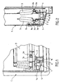
- a convector body C carries an element 1 in insulating material, on which is snapped a metal support member 2.
- the metallic support member 2 comprises two symmetrical ends 2a snap in the bases 3a of the fins 3 of a body comprising an element shielded heater and two fins 3.
- Each end 2a of the metal member 2 comprises an elastic loop engaged in a corresponding orifice made each base 3a of fins 3.
- the end of the metal member 2 opposite the ends 2a has a 2b snap conformation on the element 1 of insulating material.
- the element 1 made of insulating material has a conformation in square, with a wing 1a assembled by riveting to the bodywork C of the convector and a lower part 1b having a snap and guide conformation vertical.
- the invention thus provides the advantage of reducing the number of parts for the assembly of the heating elements, an improvement of the ergonomics, a saving mounting costs, and reducing noise due to expansion, reasons for the asymmetry of the assembly in the bodywork.
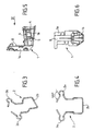
- a metal support member 2 is made by deformation of a stainless steel spring wire.
- the wire is bent to present the snap ends 2a in shape open eyelets with end segments forming an angle A of about 120 ° with the circular part of each eyelet 2a.
- the ends 2a have a narrowed dimension corresponding to the height of the holes made in the bases 3a fins 3 of the heating body.
- the orifices of the heating body have an elongated conformation in the horizontal direction, so as to allow an insertion with play in the horizontal direction and a nip after rotation of a quarter turn in the vertical direction corresponding to the assembly of Figures 1 and 2.
- the lower part 2b snap on an element 1 made of insulating material substantially U-shaped with two guided lateral branches by sliding and a lower branch intended to engage with a part an element 1 of insulating material for final locking.
- the plane of the U-shaped conformation corresponding to the snap-in end 2b is offset vertically with respect to the plane corresponding to the two latching ends 2a in the holes of the bases 3a fins 3 of the heating body.
- This vertical offset results from a partial twist median of the metallic support member 2, this twist of the elastic thread having as a function of increasing rigidity and inertia of the device while allowing a relative rotation in torsion and bending of the ends 2a with respect to the conformation 2b in U.
- an element 1 made of insulating material has a wing 1a intended to be assembled by riveting to a convector body.
- the lower part 1b of the element 1 made of insulating material has two channels 4 and 5 for guiding the vertical branches of the locking conformation 2b of the member 2 and a detent tongue 6 for locking the branch lower of the conformation 2b in U.
- the element made of insulating material is preferably manufactured by injection of a synthetic material, of the plastic material heat-resistant material, preferably polyamide.
- the thermal expansions occurring at the level of the fixing of the heating element are compensated by symmetrical mounting, while that thermal expansions likely to be produced by radiation to the heads Fastening rivets to the bodywork are prevented by the presence of the tab 8 forming a screen.
- the stiffening ribs of the insulating element 1 ensure a holding in the time and absence of vibrations transmitted by the material of the insulating element, while the slight expansions are damped by the snap-in tongue 6. contact of the lower cross member of the U-shaped snap-in conformation, acting on the way of a lever to maintain the heating body integral with the ends 2a of the support member 2.
Landscapes
- Engineering & Computer Science (AREA)
- General Engineering & Computer Science (AREA)
- Thermal Sciences (AREA)
- Mechanical Engineering (AREA)
- Physics & Mathematics (AREA)
- Chemical & Material Sciences (AREA)
- Combustion & Propulsion (AREA)
- Resistance Heating (AREA)
- Yarns And Mechanical Finishing Of Yarns Or Ropes (AREA)
- Heating, Cooling, Or Curing Plastics Or The Like In General (AREA)
- Supports For Pipes And Cables (AREA)
- Cooling Or The Like Of Semiconductors Or Solid State Devices (AREA)
- Die Bonding (AREA)
Description
- la conformation d'encliquetage sur ledit élément en matériau isolant présente une conformation en U avec deux branches de guidage latéral et une branche inférieure d'encliquetage,
- les extrémités symétriques d'encliquetage présentent chacune une conformation en oeillet élastique,
- l'élément en matériau isolant présente une conformation en équerre avec une aile de fixation à la carrosserie et une partie d'encliquetage de l'organe métallique de support de corps de chauffe,
- la partie d'encliquetage de l'élément en matériau isolant comporte deux canaux de guidage et une languette d'encliquetage,
- l'élément en matériau isolant comporte un moyen formant écran pour les moyens métalliques de fixation de l'élément en matériau isolant à la carrosserie du convecteur,
- chaque extrémité d'encliquetage est insérée à travers une ailette solidaire d'un élément chauffant blindé en forme d'épingle, de manière à constituer un assemblage apte à être encliqueté sur des éléments en matériau isolant préalablement solidarisés à la carrosserie du convecteur,
- chaque conformation d'encliquetage est une conformation plane décalée par rapport au plan défini par les extrémités d'encliquetage,
- l'organe métallique est fabriqué par mise en forme d'un fil en acier à ressort de préférence inoxydable.
- La figure 1 représente schématiquement, une vue partielle en perspective du montage d'un corps de chauffe dans un convecteur électrique à l'aide d'un dispositif selon l'invention.
- La figure 2 représente schématiquement, une vue en coupe par un plan médian vertical d'un convecteur utilisant un dispositif selon l'invention.
- La figure 3 représente schématiquement, une vue en perspective d'un organe métallique de support de dispositif selon l'invention.
- La figure 4 représente schématiquement, une vue de face d'un organe métallique de support de dispositif selon l'invention.
- La figure 5 représente schématiquement, une vue en perspective d'un élément en matériau isolant de dispositif selon l'invention.
- La figure 6 représente schématiquement, une vue dans le sens de la flèche V de la figure 5 d'un élément en matériau isolant de dispositif selon l'invention.
Claims (10)
- Dispositif de support de corps de chauffe, du type comportant un élément (1) en matériau isolant destiné à être fixé à la carrosserie (C) du convecteur et au moins un organe métallique de support (2) de corps de chauffe, caractérisé par le fait que l'organe métallique (2) de support présente deux extrémités (2a) symétriques d'encliquetage de corps de chauffe et une conformation (2b) d'encliquetage sur ledit élément (1) en matériau isolant.
- Dispositif selon la revendication 1, caractérisé par le fait que la conformation (2b) d'encliquetage sur ledit élément (1) en matériau isolant présente une conformation en U avec deux branches de guidage latéral et une branche inférieure d'encliquetage.
- Dispositif selon la revendication 1 ou la revendication 2, caractérisé par le fait que les extrémités symétriques (2a) d'encliquetage présentent chacune une conformation en oeillet élastique.
- Dispositif selon les revendications précédentes, caractérisé par le fait que l'élément (1) en matériau isolant présente une conformation en équerre avec une aile (1a) de fixation à la carrosserie et une partie (1b) d'encliquetage de l'organe (2) métallique de support de corps de chauffe.
- Dispositif selon la revendication 4, caractérisé par le fait que la partie (1b) d'encliquetage de l'élément (1) en matériau isolant comporte deux canaux (4, 5) de guidage et une languette (6) d'encliquetage.
- Dispositif selon la revendication 4 ou la revendication 5, caractérisé par le fait que l'élément (1) en matériau isolant comporte un moyen (8) formant écran pour les moyens métalliques de fixation de l'élément (1) en matériau isolant à la carrosserie du convecteur.
- Dispositif selon la revendication 6, caractérisé par le fait que le moyen (8) formant écran est une languette (8) masquant des vis ou rivets de fixation de l'élément (1) en matériau isolant à la carrosserie du convecteur.
- Dispositif selon l'une quelconque des revendications 1 à 3, caractérisé par le fait que chaque extrémité (2a) d'encliquetage est insérable à travers une ailette (3) solidaire d'un élément chauffant blindé en forme d'épingle, de manière à constituer un assemblage apte à être encliqueté sur des éléments (1) en matériau isolant préalablement solidarisés à la carrosserie (C) du convecteur.
- Dispositif selon la revendication 8, caractérisé par le fait que chaque conformation d'encliquetage (2b) est une conformation plane décalée par rapport au plan défini par les extrémités (2a) d'encliquetage.
- Dispositif selon l'une quelconque des revendications précédentes, caractérisé par le fait que l'organe (2) métallique est fabriqué par mise en forme d'un fil en acier à ressort de préférence inoxydable.
Applications Claiming Priority (2)
| Application Number | Priority Date | Filing Date | Title |
|---|---|---|---|
| FR0117012 | 2001-12-28 | ||
| FR0117012A FR2834335B1 (fr) | 2001-12-28 | 2001-12-28 | Dispositif de support de corps de chauffe |
Publications (2)
| Publication Number | Publication Date |
|---|---|
| EP1323992A1 EP1323992A1 (fr) | 2003-07-02 |
| EP1323992B1 true EP1323992B1 (fr) | 2005-05-04 |
Family
ID=8871067
Family Applications (1)
| Application Number | Title | Priority Date | Filing Date |
|---|---|---|---|
| EP02293116A Expired - Lifetime EP1323992B1 (fr) | 2001-12-28 | 2002-12-17 | Dispositif de support de corps de chauffe |
Country Status (5)
| Country | Link |
|---|---|
| EP (1) | EP1323992B1 (fr) |
| AT (1) | ATE294952T1 (fr) |
| DE (1) | DE60203985D1 (fr) |
| FR (1) | FR2834335B1 (fr) |
| NO (1) | NO20026204L (fr) |
Cited By (1)
| Publication number | Priority date | Publication date | Assignee | Title |
|---|---|---|---|---|
| DE102005052488A1 (de) * | 2005-11-03 | 2007-05-10 | Stiebel Eltron Gmbh & Co. Kg | Heizgerät, insbesondere Konvektions-Heizgerät |
Family Cites Families (4)
| Publication number | Priority date | Publication date | Assignee | Title |
|---|---|---|---|---|
| US3627984A (en) * | 1969-12-08 | 1971-12-14 | Federal Pacific Electric Co | Combined support and ground clip for heater elements |
| GB2035536B (en) * | 1978-10-11 | 1983-02-09 | Prl Soc | Heat exchanger mounting |
| FR2767911B1 (fr) | 1997-09-04 | 1999-10-29 | Atlantic Industrie Sas | Support de corps de chauffe |
| FR2805336B1 (fr) * | 2000-02-23 | 2002-05-03 | Atlantic Industrie Sas | Dispositif de support de corps de chauffe |
-
2001
- 2001-12-28 FR FR0117012A patent/FR2834335B1/fr not_active Expired - Fee Related
-
2002
- 2002-12-17 DE DE60203985T patent/DE60203985D1/de not_active Expired - Lifetime
- 2002-12-17 EP EP02293116A patent/EP1323992B1/fr not_active Expired - Lifetime
- 2002-12-17 AT AT02293116T patent/ATE294952T1/de not_active IP Right Cessation
- 2002-12-23 NO NO20026204A patent/NO20026204L/no not_active Application Discontinuation
Cited By (1)
| Publication number | Priority date | Publication date | Assignee | Title |
|---|---|---|---|---|
| DE102005052488A1 (de) * | 2005-11-03 | 2007-05-10 | Stiebel Eltron Gmbh & Co. Kg | Heizgerät, insbesondere Konvektions-Heizgerät |
Also Published As
| Publication number | Publication date |
|---|---|
| DE60203985D1 (de) | 2005-06-09 |
| FR2834335B1 (fr) | 2004-04-02 |
| NO20026204L (no) | 2003-06-30 |
| NO20026204D0 (no) | 2002-12-23 |
| ATE294952T1 (de) | 2005-05-15 |
| EP1323992A1 (fr) | 2003-07-02 |
| FR2834335A1 (fr) | 2003-07-04 |
Similar Documents
| Publication | Publication Date | Title |
|---|---|---|
| JP4874968B2 (ja) | フロントガラスのワイパー装置 | |
| EP3155941B1 (fr) | Recipient de cuisson comportant un support de capteur | |
| FR2674611A1 (fr) | Dispositif d'eclairage d'afficheurs, notamment pour appareils d'informatique. | |
| FR2492324A1 (fr) | Element elastique pour la fixation d'enjoliveur de roue | |
| WO2010023050A2 (fr) | Dispositif de fixation pour un echangeur de chaleur a ailettes, notamment pour vehicules automobiles | |
| JP6722501B2 (ja) | 樹脂カバー及び樹脂カバーを備えた車両用シート | |
| KR100447524B1 (ko) | 이륜차 차륜용 균형추 | |
| EP1323992B1 (fr) | Dispositif de support de corps de chauffe | |
| EP0262020A1 (fr) | Monture de lunettes | |
| FR2665496A1 (fr) | Etrier flottant pour frein a disque a garnitures partielles. | |
| EP2730487B1 (fr) | Organe de maintien de deux éléments de carrosserie de véhicule automobile l'un contre l'autre | |
| EP0685655B1 (fr) | Agrafe élastique de fixation | |
| EP1728687B1 (fr) | Agencement pour le montage d'un enjoliveur sur un élément de carrosserie de véhicule automobile | |
| FR2796427A1 (fr) | Dispositif de premontage d'un ecrou pour ensemble de fixation du type vis-ecrou | |
| FR2486477A1 (fr) | Dispositif d'essuyage pour glaces de vehicules automobiles | |
| EP0524069B1 (fr) | Balai d'essuie-glace du type comportant une lame déflectrice aérodynamique fixée au moyen d'une attache amovible | |
| FR3076517A1 (fr) | Balai d’essuie-glace et son procédé de montage | |
| FR2831636A1 (fr) | Dispositif de fixation d'un joint, en particulier d'un joint de soie de verre pour une porte de four de cuisson | |
| JPS58156476A (ja) | 特に自転車用レバ−とカラ−のユニツト | |
| KR0179738B1 (ko) | 차량의 사이드 실 몰딩 조립구조 | |
| EP1088172B1 (fr) | Dispositif de maintien d'un organe engage dans un orifice d'un support | |
| FR3137727A1 (fr) | Pièce de fixation | |
| FR3156089A1 (fr) | « Système d’essuyage de capteur lidar » | |
| JP4456987B2 (ja) | 巻き込み防止カバー及びこの巻き込み防止カバーが装着された自転車 | |
| FR2919247A3 (fr) | Dispositif de fixation d'un fermoir de boucle de ceinture d'un vehicule automobile et siege adapte pour recevoir un tel dispositif de fixation. |
Legal Events
| Date | Code | Title | Description |
|---|---|---|---|
| PUAI | Public reference made under article 153(3) epc to a published international application that has entered the european phase |
Free format text: ORIGINAL CODE: 0009012 |
|
| AK | Designated contracting states |
Designated state(s): AT BE BG CH CY CZ DE DK EE ES FI FR GB GR IE IT LI LU MC NL PT SE SI SK TR |
|
| AX | Request for extension of the european patent |
Extension state: AL LT LV MK RO |
|
| 17P | Request for examination filed |
Effective date: 20031227 |
|
| AKX | Designation fees paid |
Designated state(s): AT BE BG CH CY CZ DE DK EE ES FI FR GB GR IE IT LI LU MC NL PT SE SI SK TR |
|
| AXX | Extension fees paid |
Extension state: LT Payment date: 20030118 Extension state: LV Payment date: 20030118 |
|
| GRAP | Despatch of communication of intention to grant a patent |
Free format text: ORIGINAL CODE: EPIDOSNIGR1 |
|
| GRAS | Grant fee paid |
Free format text: ORIGINAL CODE: EPIDOSNIGR3 |
|
| GRAA | (expected) grant |
Free format text: ORIGINAL CODE: 0009210 |
|
| AK | Designated contracting states |
Kind code of ref document: B1 Designated state(s): AT BE BG CH CY CZ DE DK EE ES FI FR GB GR IE IT LI LU MC NL PT SE SI SK TR |
|
| AX | Request for extension of the european patent |
Extension state: LT LV |
|
| PG25 | Lapsed in a contracting state [announced via postgrant information from national office to epo] |
Ref country code: IT Free format text: LAPSE BECAUSE OF FAILURE TO SUBMIT A TRANSLATION OF THE DESCRIPTION OR TO PAY THE FEE WITHIN THE PRESCRIBED TIME-LIMIT;WARNING: LAPSES OF ITALIAN PATENTS WITH EFFECTIVE DATE BEFORE 2007 MAY HAVE OCCURRED AT ANY TIME BEFORE 2007. THE CORRECT EFFECTIVE DATE MAY BE DIFFERENT FROM THE ONE RECORDED. Effective date: 20050504 Ref country code: IE Free format text: LAPSE BECAUSE OF FAILURE TO SUBMIT A TRANSLATION OF THE DESCRIPTION OR TO PAY THE FEE WITHIN THE PRESCRIBED TIME-LIMIT Effective date: 20050504 Ref country code: GB Free format text: LAPSE BECAUSE OF FAILURE TO SUBMIT A TRANSLATION OF THE DESCRIPTION OR TO PAY THE FEE WITHIN THE PRESCRIBED TIME-LIMIT Effective date: 20050504 Ref country code: TR Free format text: LAPSE BECAUSE OF FAILURE TO SUBMIT A TRANSLATION OF THE DESCRIPTION OR TO PAY THE FEE WITHIN THE PRESCRIBED TIME-LIMIT Effective date: 20050504 Ref country code: SI Free format text: LAPSE BECAUSE OF FAILURE TO SUBMIT A TRANSLATION OF THE DESCRIPTION OR TO PAY THE FEE WITHIN THE PRESCRIBED TIME-LIMIT Effective date: 20050504 Ref country code: FI Free format text: LAPSE BECAUSE OF FAILURE TO SUBMIT A TRANSLATION OF THE DESCRIPTION OR TO PAY THE FEE WITHIN THE PRESCRIBED TIME-LIMIT Effective date: 20050504 Ref country code: SK Free format text: LAPSE BECAUSE OF FAILURE TO SUBMIT A TRANSLATION OF THE DESCRIPTION OR TO PAY THE FEE WITHIN THE PRESCRIBED TIME-LIMIT Effective date: 20050504 Ref country code: CZ Free format text: LAPSE BECAUSE OF FAILURE TO SUBMIT A TRANSLATION OF THE DESCRIPTION OR TO PAY THE FEE WITHIN THE PRESCRIBED TIME-LIMIT Effective date: 20050504 Ref country code: EE Free format text: LAPSE BECAUSE OF FAILURE TO SUBMIT A TRANSLATION OF THE DESCRIPTION OR TO PAY THE FEE WITHIN THE PRESCRIBED TIME-LIMIT Effective date: 20050504 Ref country code: AT Free format text: LAPSE BECAUSE OF FAILURE TO SUBMIT A TRANSLATION OF THE DESCRIPTION OR TO PAY THE FEE WITHIN THE PRESCRIBED TIME-LIMIT Effective date: 20050504 Ref country code: NL Free format text: LAPSE BECAUSE OF FAILURE TO SUBMIT A TRANSLATION OF THE DESCRIPTION OR TO PAY THE FEE WITHIN THE PRESCRIBED TIME-LIMIT Effective date: 20050504 |
|
| REG | Reference to a national code |
Ref country code: GB Ref legal event code: FG4D Free format text: NOT ENGLISH |
|
| REG | Reference to a national code |
Ref country code: CH Ref legal event code: EP |
|
| REG | Reference to a national code |
Ref country code: IE Ref legal event code: FG4D Free format text: LANGUAGE OF EP DOCUMENT: FRENCH |
|
| REF | Corresponds to: |
Ref document number: 60203985 Country of ref document: DE Date of ref document: 20050609 Kind code of ref document: P |
|
| PG25 | Lapsed in a contracting state [announced via postgrant information from national office to epo] |
Ref country code: DK Free format text: LAPSE BECAUSE OF FAILURE TO SUBMIT A TRANSLATION OF THE DESCRIPTION OR TO PAY THE FEE WITHIN THE PRESCRIBED TIME-LIMIT Effective date: 20050804 Ref country code: BG Free format text: LAPSE BECAUSE OF FAILURE TO SUBMIT A TRANSLATION OF THE DESCRIPTION OR TO PAY THE FEE WITHIN THE PRESCRIBED TIME-LIMIT Effective date: 20050804 Ref country code: GR Free format text: LAPSE BECAUSE OF FAILURE TO SUBMIT A TRANSLATION OF THE DESCRIPTION OR TO PAY THE FEE WITHIN THE PRESCRIBED TIME-LIMIT Effective date: 20050804 Ref country code: SE Free format text: LAPSE BECAUSE OF FAILURE TO SUBMIT A TRANSLATION OF THE DESCRIPTION OR TO PAY THE FEE WITHIN THE PRESCRIBED TIME-LIMIT Effective date: 20050804 |
|
| PG25 | Lapsed in a contracting state [announced via postgrant information from national office to epo] |
Ref country code: DE Free format text: LAPSE BECAUSE OF FAILURE TO SUBMIT A TRANSLATION OF THE DESCRIPTION OR TO PAY THE FEE WITHIN THE PRESCRIBED TIME-LIMIT Effective date: 20050805 |
|
| PG25 | Lapsed in a contracting state [announced via postgrant information from national office to epo] |
Ref country code: ES Free format text: LAPSE BECAUSE OF FAILURE TO SUBMIT A TRANSLATION OF THE DESCRIPTION OR TO PAY THE FEE WITHIN THE PRESCRIBED TIME-LIMIT Effective date: 20050815 |
|
| PG25 | Lapsed in a contracting state [announced via postgrant information from national office to epo] |
Ref country code: PT Free format text: LAPSE BECAUSE OF FAILURE TO SUBMIT A TRANSLATION OF THE DESCRIPTION OR TO PAY THE FEE WITHIN THE PRESCRIBED TIME-LIMIT Effective date: 20051017 |
|
| LTIE | Lt: invalidation of european patent or patent extension |
Effective date: 20050504 |
|
| NLV1 | Nl: lapsed or annulled due to failure to fulfill the requirements of art. 29p and 29m of the patents act | ||
| GBV | Gb: ep patent (uk) treated as always having been void in accordance with gb section 77(7)/1977 [no translation filed] |
Effective date: 20050504 |
|
| PG25 | Lapsed in a contracting state [announced via postgrant information from national office to epo] |
Ref country code: CY Free format text: LAPSE BECAUSE OF FAILURE TO SUBMIT A TRANSLATION OF THE DESCRIPTION OR TO PAY THE FEE WITHIN THE PRESCRIBED TIME-LIMIT Effective date: 20051217 |
|
| REG | Reference to a national code |
Ref country code: IE Ref legal event code: FD4D |
|
| PG25 | Lapsed in a contracting state [announced via postgrant information from national office to epo] |
Ref country code: MC Free format text: LAPSE BECAUSE OF NON-PAYMENT OF DUE FEES Effective date: 20051231 Ref country code: BE Free format text: LAPSE BECAUSE OF NON-PAYMENT OF DUE FEES Effective date: 20051231 Ref country code: LU Free format text: LAPSE BECAUSE OF NON-PAYMENT OF DUE FEES Effective date: 20051231 |
|
| PLBI | Opposition filed |
Free format text: ORIGINAL CODE: 0009260 |
|
| PLAX | Notice of opposition and request to file observation + time limit sent |
Free format text: ORIGINAL CODE: EPIDOSNOBS2 |
|
| 26 | Opposition filed |
Opponent name: STIEBEL ELTRON GMBH & CO. KG Effective date: 20060206 |
|
| PLAF | Information modified related to communication of a notice of opposition and request to file observations + time limit |
Free format text: ORIGINAL CODE: EPIDOSCOBS2 |
|
| PLBB | Reply of patent proprietor to notice(s) of opposition received |
Free format text: ORIGINAL CODE: EPIDOSNOBS3 |
|
| PG25 | Lapsed in a contracting state [announced via postgrant information from national office to epo] |
Ref country code: LI Free format text: LAPSE BECAUSE OF NON-PAYMENT OF DUE FEES Effective date: 20061231 Ref country code: CH Free format text: LAPSE BECAUSE OF NON-PAYMENT OF DUE FEES Effective date: 20061231 |
|
| PLBP | Opposition withdrawn |
Free format text: ORIGINAL CODE: 0009264 |
|
| PLBD | Termination of opposition procedure: decision despatched |
Free format text: ORIGINAL CODE: EPIDOSNOPC1 |
|
| PLBM | Termination of opposition procedure: date of legal effect published |
Free format text: ORIGINAL CODE: 0009276 |
|
| STAA | Information on the status of an ep patent application or granted ep patent |
Free format text: STATUS: OPPOSITION PROCEDURE CLOSED |
|
| 27C | Opposition proceedings terminated |
Effective date: 20070409 |
|
| REG | Reference to a national code |
Ref country code: CH Ref legal event code: PL |
|
| BERE | Be: lapsed |
Owner name: ATLANTIC INDUSTRIE Effective date: 20051231 |
|
| REG | Reference to a national code |
Ref country code: FR Ref legal event code: PLFP Year of fee payment: 14 |
|
| REG | Reference to a national code |
Ref country code: FR Ref legal event code: PLFP Year of fee payment: 15 |
|
| REG | Reference to a national code |
Ref country code: FR Ref legal event code: PLFP Year of fee payment: 16 |
|
| PGFP | Annual fee paid to national office [announced via postgrant information from national office to epo] |
Ref country code: FR Payment date: 20211224 Year of fee payment: 20 |