EP1324472A2 - Inner and outer rotor slotless electric motor with ring-type winding - Google Patents
Inner and outer rotor slotless electric motor with ring-type winding Download PDFInfo
- Publication number
- EP1324472A2 EP1324472A2 EP02018189A EP02018189A EP1324472A2 EP 1324472 A2 EP1324472 A2 EP 1324472A2 EP 02018189 A EP02018189 A EP 02018189A EP 02018189 A EP02018189 A EP 02018189A EP 1324472 A2 EP1324472 A2 EP 1324472A2
- Authority
- EP
- European Patent Office
- Prior art keywords
- iron core
- screws
- ring
- magnetic yokes
- slot
- Prior art date
- Legal status (The legal status is an assumption and is not a legal conclusion. Google has not performed a legal analysis and makes no representation as to the accuracy of the status listed.)
- Granted
Links
- 238000004804 winding Methods 0.000 title claims abstract description 19
- XEEYBQQBJWHFJM-UHFFFAOYSA-N Iron Chemical group [Fe] XEEYBQQBJWHFJM-UHFFFAOYSA-N 0.000 claims abstract description 22
- 238000010276 construction Methods 0.000 claims abstract description 5
- 230000005674 electromagnetic induction Effects 0.000 claims abstract description 4
- 230000001105 regulatory effect Effects 0.000 abstract 1
- 230000033228 biological regulation Effects 0.000 description 2
- 230000007547 defect Effects 0.000 description 1
- 230000006698 induction Effects 0.000 description 1
- 238000003780 insertion Methods 0.000 description 1
- 230000037431 insertion Effects 0.000 description 1
- 229910052742 iron Inorganic materials 0.000 description 1
- 238000000034 method Methods 0.000 description 1
- 238000005406 washing Methods 0.000 description 1
Images

Classifications
-
- D—TEXTILES; PAPER
- D06—TREATMENT OF TEXTILES OR THE LIKE; LAUNDERING; FLEXIBLE MATERIALS NOT OTHERWISE PROVIDED FOR
- D06F—LAUNDERING, DRYING, IRONING, PRESSING OR FOLDING TEXTILE ARTICLES
- D06F37/00—Details specific to washing machines covered by groups D06F21/00 - D06F25/00
- D06F37/30—Driving arrangements
- D06F37/304—Arrangements or adaptations of electric motors
-
- H—ELECTRICITY
- H02—GENERATION; CONVERSION OR DISTRIBUTION OF ELECTRIC POWER
- H02K—DYNAMO-ELECTRIC MACHINES
- H02K21/00—Synchronous motors having permanent magnets; Synchronous generators having permanent magnets
- H02K21/12—Synchronous motors having permanent magnets; Synchronous generators having permanent magnets with stationary armatures and rotating magnets
-
- Y—GENERAL TAGGING OF NEW TECHNOLOGICAL DEVELOPMENTS; GENERAL TAGGING OF CROSS-SECTIONAL TECHNOLOGIES SPANNING OVER SEVERAL SECTIONS OF THE IPC; TECHNICAL SUBJECTS COVERED BY FORMER USPC CROSS-REFERENCE ART COLLECTIONS [XRACs] AND DIGESTS
- Y02—TECHNOLOGIES OR APPLICATIONS FOR MITIGATION OR ADAPTATION AGAINST CLIMATE CHANGE
- Y02B—CLIMATE CHANGE MITIGATION TECHNOLOGIES RELATED TO BUILDINGS, e.g. HOUSING, HOUSE APPLIANCES OR RELATED END-USER APPLICATIONS
- Y02B40/00—Technologies aiming at improving the efficiency of home appliances, e.g. induction cooking or efficient technologies for refrigerators, freezers or dish washers
Definitions
- This invention relates to electromotors.
- the coil windings in the conventional electromotors are shuttle-shape, wherein the unefficient connecting sides of two ends of the coil windings are composed of two slanting sides, and the coils are so large that total resistance of coil windings of conventional brushless motor can not be reduced. Consequently, performance of motor is greatly influenced, and defects such as insufficiency of torque at low speed, low efficiency and instability in operation widely exist.
- the object of the present invention provides a novel electromotor with higher efficiency and good performance at low speed.
- Conventional iron core with slots is changed to iron core without slots, winding coils are directly wound on iron, wherein inner and outer circular peripheries face respectively to inner and outer magnets and inner and outer magnetic yokes to form a complete system of electro-magnetic induction circuit.
- Inner and outer magnets, inner and outer yokes and shaft are joined together by means of screws and connection plate to form the rotor, which rotates in the bearing housing.
- Iron core, fixed with bearing housing by positioning flange constitutes the stator.
- the said motor has advantages such as big power/volume ratio, wide speed regulation range, good performance at low speed and higher efficiency. It is especially suitable for driving motors in cases demanding wide speed regulation range, large torque at low speed, high efficiency and small volume, such as for direct-drive multi-purpose washing machine, electric-drive bicycle and so on.
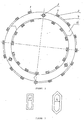
- the iron core 1 of the present invention is of a construction without slots, winding coils 2 are wound directly on iron core 1, which is split construction.
- the iron core 1 is composed of three arc-shaped iron core sections 16, whereby it is not only convenient for insertion of coils but also simplified in structure of core, resulting in lower cost.
- Each iron core has an interval 3 for screws 6 passing to fix positioning seating 4 and positioning plate 5.
- bearing housing 14 is assembled in positioning seating 4 to form the stator.
- Figure 2 shows one of the 16-pole 3-phase coils, wherein A is the beginning terminal and X is the end terminal. From beginning to end terminal, each coil is wound in forward and backward directions sequentially, connecting through bridge wires 7.
- the inner and outer peripheries of winding coils wound on iron core face respectively to inner and outer magnets 8, 9 and inner and outer magnetic yokes 10, 11, together forming a complete system of electromagnetic induction circuit.
- Inner and outer magnets 8, 9, inner and outer magnetic yokes 10, 11 and rotating shaft are joined respectively to joining plate 13 through screws to form the rotor, rotating in bearing housing 14.
Landscapes
- Engineering & Computer Science (AREA)
- Textile Engineering (AREA)
- Power Engineering (AREA)
- Iron Core Of Rotating Electric Machines (AREA)
- Motor Or Generator Frames (AREA)
- Insulation, Fastening Of Motor, Generator Windings (AREA)
- Windings For Motors And Generators (AREA)
Abstract
Description
Claims (2)
- A slot-less electromotor having inner and outer rotors as well as ring-type windings, comprising iron core (1) with winding coils (2) wound thereon, the iron core passing through positioning plate (5) underside, the positioning seating (4) thereof secured to bearing housing (4) by screws to form stator, wherein the winding coils (2) being ringed around the iron core (1), the inner and the outer peripheries thereof respectively corresponding to inner and outer magnets (8, 9) and the inner and outer magnetic yokes (10,11) to form an entire assembly of electromagnetic induction circuit, the inner and outer magnets (8, 9) and the inner and outer magnetic yokes (10, 11) as well as rotating shaft (12) joined to connecting plate (13) by screws to form the rotors, which rotate within the bearing housing (14).
- A slot-less electromotor of Claim 1, wherein the iron core (1) is split construction, composed of three arc-shaped iron core sections (16), each iron core is provided with an interval (3), through which screws (6) pass to fix the positioning seating (4) and positioning plate (5) in position at the interval.
Applications Claiming Priority (2)
| Application Number | Priority Date | Filing Date | Title |
|---|---|---|---|
| CN01145511A CN1133260C (en) | 2001-12-25 | 2001-12-25 | Electric machine with ring windings on internal and external rotors without slots |
| CN01145511 | 2001-12-25 |
Publications (3)
| Publication Number | Publication Date |
|---|---|
| EP1324472A2 true EP1324472A2 (en) | 2003-07-02 |
| EP1324472A3 EP1324472A3 (en) | 2005-10-05 |
| EP1324472B1 EP1324472B1 (en) | 2010-03-17 |
Family
ID=4678203
Family Applications (1)
| Application Number | Title | Priority Date | Filing Date |
|---|---|---|---|
| EP02018189A Expired - Lifetime EP1324472B1 (en) | 2001-12-25 | 2002-08-20 | Inner and outer rotor slotless electric motor with ring-type winding |
Country Status (4)
| Country | Link |
|---|---|
| EP (1) | EP1324472B1 (en) |
| CN (1) | CN1133260C (en) |
| AT (1) | ATE461548T1 (en) |
| DE (1) | DE60235685D1 (en) |
Cited By (9)
| Publication number | Priority date | Publication date | Assignee | Title |
|---|---|---|---|---|
| WO2011014934A1 (en) | 2009-08-03 | 2011-02-10 | Atlas Copco Airpower | Turbocompressor system |
| EP3035501A1 (en) | 2014-12-18 | 2016-06-22 | Siemens Aktiengesellschaft | Stator for an electric machine |
| EP3035500A1 (en) | 2014-12-18 | 2016-06-22 | Siemens Aktiengesellschaft | Stator segment for a hollow cylindrical segmented stator of an electric machine |
| CN107489701A (en) * | 2016-06-12 | 2017-12-19 | 安徽聚隆传动科技股份有限公司 | A kind of two-power washing machine bucket attachment means |
| CN109067123A (en) * | 2018-07-31 | 2018-12-21 | 华南理工大学 | A kind of brushless slotless of Novel splicing formula is without rectification adverser permanent magnet DC motor |
| WO2019077261A1 (en) | 2017-10-17 | 2019-04-25 | Moving Magnet Technologies | Toroidal polyphase electric machine |
| RU2686686C1 (en) * | 2018-07-09 | 2019-04-30 | Акционерное общество "Мостком" | Instant precision motor |
| CN111463929A (en) * | 2020-04-03 | 2020-07-28 | 中国航发哈尔滨东安发动机有限公司 | High-speed motor stator without inner groove |
| WO2024157213A1 (en) * | 2023-01-27 | 2024-08-02 | Dyson Technology Limited | A stator assembly |
Families Citing this family (6)
| Publication number | Priority date | Publication date | Assignee | Title |
|---|---|---|---|---|
| CN101083411B (en) * | 2006-05-30 | 2010-08-25 | 比亚迪股份有限公司 | Permanent-magnetic electric machine rotor magnet steel fixing structure |
| CN101820209B (en) * | 2009-02-27 | 2012-11-07 | 金健 | Coaxial double-output brushless motor |
| CN105453394B (en) * | 2013-08-09 | 2018-09-21 | 深圳市配天电机技术有限公司 | A kind of double-rotor machine and fan, compressor using this motor |
| CN105281511A (en) * | 2015-11-18 | 2016-01-27 | 张喜明 | A compound type motor |
| CN107620714A (en) * | 2017-09-29 | 2018-01-23 | 广东威灵电机制造有限公司 | Electronic water pump |
| CN116388417B (en) * | 2023-02-10 | 2024-06-07 | 张勇 | Slotless ultra-high-speed permanent magnet motor with variable radial surrounding winding distribution structure |
Family Cites Families (4)
| Publication number | Priority date | Publication date | Assignee | Title |
|---|---|---|---|---|
| JPS5315502A (en) * | 1976-07-28 | 1978-02-13 | Hitachi Ltd | Rotary electric machine |
| JPS5441401A (en) * | 1977-09-07 | 1979-04-02 | Hitachi Ltd | Stator core in motor |
| US5172021A (en) * | 1991-07-03 | 1992-12-15 | Fuji Xerox Co., Ltd. | Deflector motor with gas bearing and magnet thrust bearing |
| AU1092799A (en) * | 1997-10-16 | 1999-05-03 | Steven L. Sullivan | Generators and transformers with toroidally wound stator winding |
-
2001
- 2001-12-25 CN CN01145511A patent/CN1133260C/en not_active Expired - Fee Related
-
2002
- 2002-08-20 EP EP02018189A patent/EP1324472B1/en not_active Expired - Lifetime
- 2002-08-20 AT AT02018189T patent/ATE461548T1/en not_active IP Right Cessation
- 2002-08-20 DE DE60235685T patent/DE60235685D1/en not_active Expired - Lifetime
Cited By (14)
| Publication number | Priority date | Publication date | Assignee | Title |
|---|---|---|---|---|
| WO2011014934A1 (en) | 2009-08-03 | 2011-02-10 | Atlas Copco Airpower | Turbocompressor system |
| US20120128512A1 (en) * | 2009-08-03 | 2012-05-24 | Atlas Copco Airpower | Turbocompressor system |
| US9470238B2 (en) | 2009-08-03 | 2016-10-18 | Atlas Copco Airpower, Naamloze Vennootschap | Electric motor having segmented stator windings |
| EP3035500A1 (en) | 2014-12-18 | 2016-06-22 | Siemens Aktiengesellschaft | Stator segment for a hollow cylindrical segmented stator of an electric machine |
| WO2016096348A1 (en) | 2014-12-18 | 2016-06-23 | Siemens Aktiengesellschaft | Stator segment for a hollow cylinder-shaped, segmented stator of an electrical machine |
| WO2016096343A1 (en) | 2014-12-18 | 2016-06-23 | Siemens Aktiengesellschaft | Stator for an electrical machine |
| EP3035501A1 (en) | 2014-12-18 | 2016-06-22 | Siemens Aktiengesellschaft | Stator for an electric machine |
| CN107489701A (en) * | 2016-06-12 | 2017-12-19 | 安徽聚隆传动科技股份有限公司 | A kind of two-power washing machine bucket attachment means |
| WO2019077261A1 (en) | 2017-10-17 | 2019-04-25 | Moving Magnet Technologies | Toroidal polyphase electric machine |
| US11967870B2 (en) | 2017-10-17 | 2024-04-23 | Moving Magnet Technologies | Toroidal polyphase electric machine |
| RU2686686C1 (en) * | 2018-07-09 | 2019-04-30 | Акционерное общество "Мостком" | Instant precision motor |
| CN109067123A (en) * | 2018-07-31 | 2018-12-21 | 华南理工大学 | A kind of brushless slotless of Novel splicing formula is without rectification adverser permanent magnet DC motor |
| CN111463929A (en) * | 2020-04-03 | 2020-07-28 | 中国航发哈尔滨东安发动机有限公司 | High-speed motor stator without inner groove |
| WO2024157213A1 (en) * | 2023-01-27 | 2024-08-02 | Dyson Technology Limited | A stator assembly |
Also Published As
| Publication number | Publication date |
|---|---|
| DE60235685D1 (en) | 2010-04-29 |
| EP1324472B1 (en) | 2010-03-17 |
| CN1373544A (en) | 2002-10-09 |
| EP1324472A3 (en) | 2005-10-05 |
| CN1133260C (en) | 2003-12-31 |
| ATE461548T1 (en) | 2010-04-15 |
Similar Documents
| Publication | Publication Date | Title |
|---|---|---|
| JP3983423B2 (en) | Electric motor | |
| US7626299B2 (en) | Motor | |
| US6995494B2 (en) | Axial gap brushless DC motor | |
| US6590312B1 (en) | Rotary electric machine having a permanent magnet stator and permanent magnet rotor | |
| US6975049B2 (en) | Electrical machine and method of manufacturing the same | |
| EP1324472B1 (en) | Inner and outer rotor slotless electric motor with ring-type winding | |
| CN101291095B (en) | Hybrid switch reluctance motor | |
| EP1043827A3 (en) | Rotor for permanent magnet type rotating machine | |
| US20090134735A1 (en) | Motor having twin-rotor and apparatus having the same | |
| JP2010063196A (en) | Axial gap motor and electromotive fluid drive unit | |
| JP2003032978A (en) | Rotating electric machine | |
| JP7771420B2 (en) | Harmonic magnetic field drive motor | |
| JP2011120465A (en) | Two-phase bldc motor | |
| JP5188746B2 (en) | Brushless DC motor | |
| JP7193422B2 (en) | Rotating electric machine and manufacturing method of rotating electric machine | |
| CN114726180A (en) | Wide-narrow stator pole axial flux switch reluctance motor and control method thereof | |
| JP3117164B2 (en) | Permanent magnet rotating electric machine, control method and control device thereof, and electric vehicle using the same | |
| US20250149940A1 (en) | Flux-concentrated motor | |
| CN207150380U (en) | A kind of rotor alternate angle stator magnetic barrier type axial permanent magnetic aids in double salient-pole electric machine | |
| CN116191800B (en) | Short magnetic circuit shaft radial mixed magnetic flux switch reluctance motor and control method | |
| CN217956802U (en) | Composite excitation weak-magnetism-free permanent magnet water-cooling driving motor | |
| JP4491211B2 (en) | Permanent magnet rotating electric machine | |
| EP2028747A1 (en) | Two-phase DC brushless motor | |
| KR20210104351A (en) | High efficient Permanent magnet Generator of cogging torque reduction | |
| JP3632721B2 (en) | Permanent magnet synchronous motor |
Legal Events
| Date | Code | Title | Description |
|---|---|---|---|
| PUAI | Public reference made under article 153(3) epc to a published international application that has entered the european phase |
Free format text: ORIGINAL CODE: 0009012 |
|
| AK | Designated contracting states |
Designated state(s): AT BE BG CH CY CZ DE DK EE ES FI FR GB GR IE IT LI LU MC NL PT SE SK TR |
|
| AX | Request for extension of the european patent |
Extension state: AL LT LV MK RO SI |
|
| PUAL | Search report despatched |
Free format text: ORIGINAL CODE: 0009013 |
|
| AK | Designated contracting states |
Kind code of ref document: A3 Designated state(s): AT BE BG CH CY CZ DE DK EE ES FI FR GB GR IE IT LI LU MC NL PT SE SK TR |
|
| AX | Request for extension of the european patent |
Extension state: AL LT LV MK RO SI |
|
| RIC1 | Information provided on ipc code assigned before grant |
Ipc: 7H 02K 1/18 A Ipc: 7H 02K 1/12 B Ipc: 7H 02K 16/02 B |
|
| 17P | Request for examination filed |
Effective date: 20060317 |
|
| AKX | Designation fees paid |
Designated state(s): AT BE BG CH CY CZ DE DK EE ES FI FR GB GR IE IT LI LU MC NL PT SE SK TR |
|
| GRAP | Despatch of communication of intention to grant a patent |
Free format text: ORIGINAL CODE: EPIDOSNIGR1 |
|
| GRAS | Grant fee paid |
Free format text: ORIGINAL CODE: EPIDOSNIGR3 |
|
| GRAA | (expected) grant |
Free format text: ORIGINAL CODE: 0009210 |
|
| AK | Designated contracting states |
Kind code of ref document: B1 Designated state(s): AT BE BG CH CY CZ DE DK EE ES FI FR GB GR IE IT LI LU MC NL PT SE SK TR |
|
| REG | Reference to a national code |
Ref country code: GB Ref legal event code: FG4D |
|
| REG | Reference to a national code |
Ref country code: CH Ref legal event code: EP |
|
| REG | Reference to a national code |
Ref country code: IE Ref legal event code: FG4D |
|
| REF | Corresponds to: |
Ref document number: 60235685 Country of ref document: DE Date of ref document: 20100429 Kind code of ref document: P |
|
| REG | Reference to a national code |
Ref country code: NL Ref legal event code: VDEP Effective date: 20100317 |
|
| PG25 | Lapsed in a contracting state [announced via postgrant information from national office to epo] |
Ref country code: FI Free format text: LAPSE BECAUSE OF FAILURE TO SUBMIT A TRANSLATION OF THE DESCRIPTION OR TO PAY THE FEE WITHIN THE PRESCRIBED TIME-LIMIT Effective date: 20100317 Ref country code: AT Free format text: LAPSE BECAUSE OF FAILURE TO SUBMIT A TRANSLATION OF THE DESCRIPTION OR TO PAY THE FEE WITHIN THE PRESCRIBED TIME-LIMIT Effective date: 20100317 |
|
| PG25 | Lapsed in a contracting state [announced via postgrant information from national office to epo] |
Ref country code: EE Free format text: LAPSE BECAUSE OF FAILURE TO SUBMIT A TRANSLATION OF THE DESCRIPTION OR TO PAY THE FEE WITHIN THE PRESCRIBED TIME-LIMIT Effective date: 20100317 Ref country code: CY Free format text: LAPSE BECAUSE OF FAILURE TO SUBMIT A TRANSLATION OF THE DESCRIPTION OR TO PAY THE FEE WITHIN THE PRESCRIBED TIME-LIMIT Effective date: 20100317 Ref country code: BE Free format text: LAPSE BECAUSE OF FAILURE TO SUBMIT A TRANSLATION OF THE DESCRIPTION OR TO PAY THE FEE WITHIN THE PRESCRIBED TIME-LIMIT Effective date: 20100317 Ref country code: SE Free format text: LAPSE BECAUSE OF FAILURE TO SUBMIT A TRANSLATION OF THE DESCRIPTION OR TO PAY THE FEE WITHIN THE PRESCRIBED TIME-LIMIT Effective date: 20100317 Ref country code: NL Free format text: LAPSE BECAUSE OF FAILURE TO SUBMIT A TRANSLATION OF THE DESCRIPTION OR TO PAY THE FEE WITHIN THE PRESCRIBED TIME-LIMIT Effective date: 20100317 Ref country code: GR Free format text: LAPSE BECAUSE OF FAILURE TO SUBMIT A TRANSLATION OF THE DESCRIPTION OR TO PAY THE FEE WITHIN THE PRESCRIBED TIME-LIMIT Effective date: 20100618 Ref country code: ES Free format text: LAPSE BECAUSE OF FAILURE TO SUBMIT A TRANSLATION OF THE DESCRIPTION OR TO PAY THE FEE WITHIN THE PRESCRIBED TIME-LIMIT Effective date: 20100628 |
|
| PG25 | Lapsed in a contracting state [announced via postgrant information from national office to epo] |
Ref country code: CZ Free format text: LAPSE BECAUSE OF FAILURE TO SUBMIT A TRANSLATION OF THE DESCRIPTION OR TO PAY THE FEE WITHIN THE PRESCRIBED TIME-LIMIT Effective date: 20100317 Ref country code: SK Free format text: LAPSE BECAUSE OF FAILURE TO SUBMIT A TRANSLATION OF THE DESCRIPTION OR TO PAY THE FEE WITHIN THE PRESCRIBED TIME-LIMIT Effective date: 20100317 Ref country code: BG Free format text: LAPSE BECAUSE OF FAILURE TO SUBMIT A TRANSLATION OF THE DESCRIPTION OR TO PAY THE FEE WITHIN THE PRESCRIBED TIME-LIMIT Effective date: 20100617 |
|
| PLBE | No opposition filed within time limit |
Free format text: ORIGINAL CODE: 0009261 |
|
| STAA | Information on the status of an ep patent application or granted ep patent |
Free format text: STATUS: NO OPPOSITION FILED WITHIN TIME LIMIT |
|
| PG25 | Lapsed in a contracting state [announced via postgrant information from national office to epo] |
Ref country code: PT Free format text: LAPSE BECAUSE OF FAILURE TO SUBMIT A TRANSLATION OF THE DESCRIPTION OR TO PAY THE FEE WITHIN THE PRESCRIBED TIME-LIMIT Effective date: 20100719 Ref country code: DK Free format text: LAPSE BECAUSE OF FAILURE TO SUBMIT A TRANSLATION OF THE DESCRIPTION OR TO PAY THE FEE WITHIN THE PRESCRIBED TIME-LIMIT Effective date: 20100317 |
|
| 26N | No opposition filed |
Effective date: 20101220 |
|
| PG25 | Lapsed in a contracting state [announced via postgrant information from national office to epo] |
Ref country code: IT Free format text: LAPSE BECAUSE OF FAILURE TO SUBMIT A TRANSLATION OF THE DESCRIPTION OR TO PAY THE FEE WITHIN THE PRESCRIBED TIME-LIMIT Effective date: 20100317 Ref country code: MC Free format text: LAPSE BECAUSE OF NON-PAYMENT OF DUE FEES Effective date: 20100831 |
|
| REG | Reference to a national code |
Ref country code: CH Ref legal event code: PL |
|
| GBPC | Gb: european patent ceased through non-payment of renewal fee |
Effective date: 20100820 |
|
| PG25 | Lapsed in a contracting state [announced via postgrant information from national office to epo] |
Ref country code: LI Free format text: LAPSE BECAUSE OF NON-PAYMENT OF DUE FEES Effective date: 20100831 Ref country code: CH Free format text: LAPSE BECAUSE OF NON-PAYMENT OF DUE FEES Effective date: 20100831 |
|
| PG25 | Lapsed in a contracting state [announced via postgrant information from national office to epo] |
Ref country code: IE Free format text: LAPSE BECAUSE OF NON-PAYMENT OF DUE FEES Effective date: 20100820 |
|
| PG25 | Lapsed in a contracting state [announced via postgrant information from national office to epo] |
Ref country code: GB Free format text: LAPSE BECAUSE OF NON-PAYMENT OF DUE FEES Effective date: 20100820 |
|
| PGFP | Annual fee paid to national office [announced via postgrant information from national office to epo] |
Ref country code: FR Payment date: 20110907 Year of fee payment: 10 Ref country code: DE Payment date: 20110914 Year of fee payment: 10 |
|
| PG25 | Lapsed in a contracting state [announced via postgrant information from national office to epo] |
Ref country code: LU Free format text: LAPSE BECAUSE OF NON-PAYMENT OF DUE FEES Effective date: 20100820 |
|
| PG25 | Lapsed in a contracting state [announced via postgrant information from national office to epo] |
Ref country code: TR Free format text: LAPSE BECAUSE OF FAILURE TO SUBMIT A TRANSLATION OF THE DESCRIPTION OR TO PAY THE FEE WITHIN THE PRESCRIBED TIME-LIMIT Effective date: 20100317 |
|
| REG | Reference to a national code |
Ref country code: FR Ref legal event code: ST Effective date: 20130430 |
|
| PG25 | Lapsed in a contracting state [announced via postgrant information from national office to epo] |
Ref country code: DE Free format text: LAPSE BECAUSE OF NON-PAYMENT OF DUE FEES Effective date: 20130301 |
|
| PG25 | Lapsed in a contracting state [announced via postgrant information from national office to epo] |
Ref country code: FR Free format text: LAPSE BECAUSE OF NON-PAYMENT OF DUE FEES Effective date: 20120831 |
|
| REG | Reference to a national code |
Ref country code: DE Ref legal event code: R082 Ref document number: 60235685 Country of ref document: DE Representative=s name: PATRONUS IP PATENT- & RECHTSANWAELTE BERNHARD , DE |
|
| REG | Reference to a national code |
Ref country code: DE Ref legal event code: R119 Ref document number: 60235685 Country of ref document: DE Effective date: 20130301 |