EP1331072B1 - Verfahren und Vorrichtung zur gesteuerten Entnahme von flüssigen Materialien aus mehreren Vorlagebehältern - Google Patents
Verfahren und Vorrichtung zur gesteuerten Entnahme von flüssigen Materialien aus mehreren Vorlagebehältern Download PDFInfo
- Publication number
- EP1331072B1 EP1331072B1 EP02001853A EP02001853A EP1331072B1 EP 1331072 B1 EP1331072 B1 EP 1331072B1 EP 02001853 A EP02001853 A EP 02001853A EP 02001853 A EP02001853 A EP 02001853A EP 1331072 B1 EP1331072 B1 EP 1331072B1
- Authority
- EP
- European Patent Office
- Prior art keywords
- supply
- supply containers
- containers
- filled
- pulse frequency
- Prior art date
- Legal status (The legal status is an assumption and is not a legal conclusion. Google has not performed a legal analysis and makes no representation as to the accuracy of the status listed.)
- Expired - Lifetime
Links
- 239000000463 material Substances 0.000 title claims abstract description 18
- 238000000034 method Methods 0.000 title claims description 14
- 239000007788 liquid Substances 0.000 claims description 10
- 239000011344 liquid material Substances 0.000 claims description 3
- 230000001419 dependent effect Effects 0.000 claims description 2
- 230000004308 accommodation Effects 0.000 claims 1
- 238000007872 degassing Methods 0.000 claims 1
- 238000001746 injection moulding Methods 0.000 claims 1
- 238000009434 installation Methods 0.000 claims 1
- 238000011835 investigation Methods 0.000 claims 1
- 239000012530 fluid Substances 0.000 abstract description 10
- 238000012544 monitoring process Methods 0.000 abstract 1
- 238000004140 cleaning Methods 0.000 description 4
- 239000000126 substance Substances 0.000 description 4
- 239000007795 chemical reaction product Substances 0.000 description 2
- 238000011161 development Methods 0.000 description 2
- 230000018109 developmental process Effects 0.000 description 2
- 238000002347 injection Methods 0.000 description 2
- 239000007924 injection Substances 0.000 description 2
- 239000004033 plastic Substances 0.000 description 2
- 229920003023 plastic Polymers 0.000 description 2
- 238000005507 spraying Methods 0.000 description 2
- 230000000740 bleeding effect Effects 0.000 description 1
- 239000011248 coating agent Substances 0.000 description 1
- 238000000576 coating method Methods 0.000 description 1
- 238000004891 communication Methods 0.000 description 1
- 238000013461 design Methods 0.000 description 1
- 239000002920 hazardous waste Substances 0.000 description 1
- 238000007654 immersion Methods 0.000 description 1
- 239000004413 injection moulding compound Substances 0.000 description 1
- 238000012986 modification Methods 0.000 description 1
- 230000004048 modification Effects 0.000 description 1
- 229920001296 polysiloxane Polymers 0.000 description 1
- 239000011527 polyurethane coating Substances 0.000 description 1
- 238000007493 shaping process Methods 0.000 description 1
- 238000009423 ventilation Methods 0.000 description 1
- 239000002699 waste material Substances 0.000 description 1
Images


Classifications
-
- B—PERFORMING OPERATIONS; TRANSPORTING
- B01—PHYSICAL OR CHEMICAL PROCESSES OR APPARATUS IN GENERAL
- B01F—MIXING, e.g. DISSOLVING, EMULSIFYING OR DISPERSING
- B01F35/00—Accessories for mixers; Auxiliary operations or auxiliary devices; Parts or details of general application
- B01F35/80—Forming a predetermined ratio of the substances to be mixed
- B01F35/83—Forming a predetermined ratio of the substances to be mixed by controlling the ratio of two or more flows, e.g. using flow sensing or flow controlling devices
-
- B—PERFORMING OPERATIONS; TRANSPORTING
- B29—WORKING OF PLASTICS; WORKING OF SUBSTANCES IN A PLASTIC STATE IN GENERAL
- B29B—PREPARATION OR PRETREATMENT OF THE MATERIAL TO BE SHAPED; MAKING GRANULES OR PREFORMS; RECOVERY OF PLASTICS OR OTHER CONSTITUENTS OF WASTE MATERIAL CONTAINING PLASTICS
- B29B7/00—Mixing; Kneading
- B29B7/74—Mixing; Kneading using other mixers or combinations of mixers, e.g. of dissimilar mixers ; Plant
- B29B7/76—Mixers with stream-impingement mixing head
- B29B7/7615—Mixers with stream-impingement mixing head characterised by arrangements for controlling, measuring or regulating, e.g. for feeding or proportioning the components
- B29B7/7626—Mixers with stream-impingement mixing head characterised by arrangements for controlling, measuring or regulating, e.g. for feeding or proportioning the components using measuring chambers of piston or plunger type
-
- B—PERFORMING OPERATIONS; TRANSPORTING
- B01—PHYSICAL OR CHEMICAL PROCESSES OR APPARATUS IN GENERAL
- B01F—MIXING, e.g. DISSOLVING, EMULSIFYING OR DISPERSING
- B01F35/00—Accessories for mixers; Auxiliary operations or auxiliary devices; Parts or details of general application
- B01F35/71—Feed mechanisms
- B01F35/712—Feed mechanisms for feeding fluids
-
- B—PERFORMING OPERATIONS; TRANSPORTING
- B01—PHYSICAL OR CHEMICAL PROCESSES OR APPARATUS IN GENERAL
- B01F—MIXING, e.g. DISSOLVING, EMULSIFYING OR DISPERSING
- B01F35/00—Accessories for mixers; Auxiliary operations or auxiliary devices; Parts or details of general application
- B01F35/71—Feed mechanisms
- B01F35/717—Feed mechanisms characterised by the means for feeding the components to the mixer
- B01F35/7174—Feed mechanisms characterised by the means for feeding the components to the mixer using pistons, plungers or syringes
-
- B—PERFORMING OPERATIONS; TRANSPORTING
- B01—PHYSICAL OR CHEMICAL PROCESSES OR APPARATUS IN GENERAL
- B01F—MIXING, e.g. DISSOLVING, EMULSIFYING OR DISPERSING
- B01F35/00—Accessories for mixers; Auxiliary operations or auxiliary devices; Parts or details of general application
- B01F35/71—Feed mechanisms
- B01F35/717—Feed mechanisms characterised by the means for feeding the components to the mixer
- B01F35/7176—Feed mechanisms characterised by the means for feeding the components to the mixer using pumps
- B01F35/717613—Piston pumps
-
- B—PERFORMING OPERATIONS; TRANSPORTING
- B05—SPRAYING OR ATOMISING IN GENERAL; APPLYING FLUENT MATERIALS TO SURFACES, IN GENERAL
- B05C—APPARATUS FOR APPLYING FLUENT MATERIALS TO SURFACES, IN GENERAL
- B05C11/00—Component parts, details or accessories not specifically provided for in groups B05C1/00 - B05C9/00
- B05C11/10—Storage, supply or control of liquid or other fluent material; Recovery of excess liquid or other fluent material
- B05C11/1036—Means for supplying a selected one of a plurality of liquids or other fluent materials, or several in selected proportions, to the applying apparatus
-
- B—PERFORMING OPERATIONS; TRANSPORTING
- B67—OPENING, CLOSING OR CLEANING BOTTLES, JARS OR SIMILAR CONTAINERS; LIQUID HANDLING
- B67D—DISPENSING, DELIVERING OR TRANSFERRING LIQUIDS, NOT OTHERWISE PROVIDED FOR
- B67D7/00—Apparatus or devices for transferring liquids from bulk storage containers or reservoirs into vehicles or into portable containers, e.g. for retail sale purposes
- B67D7/06—Details or accessories
- B67D7/58—Arrangements of pumps
- B67D7/62—Arrangements of pumps power operated
- B67D7/64—Arrangements of pumps power operated of piston type
- B67D7/645—Barrel pumps
-
- B—PERFORMING OPERATIONS; TRANSPORTING
- B01—PHYSICAL OR CHEMICAL PROCESSES OR APPARATUS IN GENERAL
- B01F—MIXING, e.g. DISSOLVING, EMULSIFYING OR DISPERSING
- B01F35/00—Accessories for mixers; Auxiliary operations or auxiliary devices; Parts or details of general application
- B01F35/71—Feed mechanisms
-
- B—PERFORMING OPERATIONS; TRANSPORTING
- B05—SPRAYING OR ATOMISING IN GENERAL; APPLYING FLUENT MATERIALS TO SURFACES, IN GENERAL
- B05C—APPARATUS FOR APPLYING FLUENT MATERIALS TO SURFACES, IN GENERAL
- B05C11/00—Component parts, details or accessories not specifically provided for in groups B05C1/00 - B05C9/00
- B05C11/11—Vats or other containers for liquids or other fluent materials
-
- B—PERFORMING OPERATIONS; TRANSPORTING
- B29—WORKING OF PLASTICS; WORKING OF SUBSTANCES IN A PLASTIC STATE IN GENERAL
- B29C—SHAPING OR JOINING OF PLASTICS; SHAPING OF MATERIAL IN A PLASTIC STATE, NOT OTHERWISE PROVIDED FOR; AFTER-TREATMENT OF THE SHAPED PRODUCTS, e.g. REPAIRING
- B29C31/00—Handling, e.g. feeding of the material to be shaped, storage of plastics material before moulding; Automation, i.e. automated handling lines in plastics processing plants, e.g. using manipulators or robots
- B29C31/04—Feeding of the material to be moulded, e.g. into a mould cavity
- B29C31/06—Feeding of the material to be moulded, e.g. into a mould cavity in measured doses, e.g. by weighting
- B29C31/061—Feeding of the material to be moulded, e.g. into a mould cavity in measured doses, e.g. by weighting using stationary volumetric measuring chambers
- B29C31/063—Feeding of the material to be moulded, e.g. into a mould cavity in measured doses, e.g. by weighting using stationary volumetric measuring chambers of the piston type
-
- B—PERFORMING OPERATIONS; TRANSPORTING
- B29—WORKING OF PLASTICS; WORKING OF SUBSTANCES IN A PLASTIC STATE IN GENERAL
- B29K—INDEXING SCHEME ASSOCIATED WITH SUBCLASSES B29B, B29C OR B29D, RELATING TO MOULDING MATERIALS OR TO MATERIALS FOR MOULDS, REINFORCEMENTS, FILLERS OR PREFORMED PARTS, e.g. INSERTS
- B29K2083/00—Use of polymers having silicon, with or without sulfur, nitrogen, oxygen, or carbon only, in the main chain, as moulding material
- B29K2083/005—LSR, i.e. liquid silicone rubbers, or derivatives thereof
Definitions
- the present invention relates to a method and a device for controlled removal of liquid materials from several storage containers and supply of these substances a mixing unit.
- US 4,167,151 protects an automatic spraying device for coating objects with polyurethane coatings, which consist of two liquid immediately before spraying Components are mixed.
- Such devices are used to plastic injection molding compounds, which immediately are mixed with one another in the desired manner before being fed to the shaping device To put the mixing ratio together.
- silicone injection molded parts are made up of two different components together, so far the components on each other are agreed that their mixing ratio corresponds to about 50:50.
- the storage containers are usually arranged directly next to one another.
- the Template materials are coordinated by the manufacturer. It is therefore necessary always operate related container at the same time. Once a Storage container is emptied, both storage containers must therefore be replaced. there are also the parts of the device touching the original material with each change clean.
- the current standard storage containers have a volume of 20 or 200 liters on. The users are due to the shorter guideline time, which is particularly important for the Cleaning must be used, the 200 liter container is often preferred, although these are more difficult to manipulate due to the high weight.
- a so-called follower plate is placed on each container, which has a valve opening has, this valve opens when the follower plate contacts the substance and allows existing air in the container to escape. This process is done by creating a predetermined pressure on the follower plate supported. Once the bleeding is complete, the valve is closed. Then one is driven by a pneumatic cylinder Bucket piston pump immersed in the material. The immersion cycle is the Controlled amount of liquid substance. The scoop piston pump manages it removed material to a mixing channel in which the substance with another liquid component is mixed.
- EP 0 112 638 proposes a device for mixing and dispensing of a fluid, which has two storage containers for two different fluids. Each A feed pump is assigned to the storage container. Furthermore, a drive device for the Pumps, a device that connects the pumps together to remove fluid from the Storage containers in a proportionate manner with a predetermined volume ratio pump, a mixing head with inlet channels, which are in fluid communication with outlet channels of the respective pumps are provided. The pumps are driven by the drive unit corresponding speeds driven, which are inversely proportional to the respective viscosities of the pumped fluid. Furthermore, facilities are connected with the inlet side of the pumps provided to determine when a reservoir is emptied is so that the drive of the pumps can be set in time.
- EP 0 904 927 describes a device for injecting at least one two components of existing plastic known in a mold, the components via a volumetric dosing unit of a mixing device and via this one Injection cylinders are supplied.
- the present invention therefore has as its object a method for the control of a To create device of the type mentioned, the goal of the complete emptying of Storage container is. This object is achieved by the features specified in claim 1. Advantageous further developments of this method are set out in the dependent claims 2 to 5 cited.
- the invention has for its object to provide a device which the inventive method can be operated, with an improved Embodiment should take into account the fact that the full Do not empty the storage containers by means of disruptive fastening devices on the underside of the follower plates is to be restricted.
- the invention sets itself the task of being as simple as possible and not very strenuous To allow manipulation when changing the storage container and the time required for the change from a storage container to a subsequent storage container to save time design, cleaning the side of the follower plate touching the original material should be done as quickly and easily as possible.
- Both storage containers are changed at the same time.
- the control uses this to calculate the optimal mixing ratio, which must be within the specified tolerance limits.
- This optimal Mixing ratio is controlled by controlling the individual scoop piston pumps different pulse frequencies sought. However, due to the different compressibility of the original materials in the course of emptying the storage container again to deviations in the ratio of Fill levels of the individual storage containers. These deviations are from Control system recognized and continuously considered in the calculation of the pulse frequency.
- the base plate has a height that is as easy and gentle as possible offset areas for the assembly of transport rollers. This allows the base plate arranged very close to the ground and the full storage container can be easily opened this base plate can be tilted.
- the follower plates are like this attached to the device that no protruding screw heads on the the Project the side of the follower plate in contact with the liquid surface. This allows the Cleaning process can be carried out more quickly and easily.
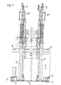
- Fig. 1 shows a side view of the device according to the invention.
- Fig. 2 shows another, around 90 Degree rotated side view of the device.
- Fig. 3 shows a top view of the same Contraption.
- the device according to the invention consists of a holding frame 1, which is attached to a base plate 2, the location of the device via Rollers 3 can be changed with minimal effort.
- the footprint is dimensioned that they are suitable for holding two containers 4 each with a capacity of 200 liters is.
- they are Areas 5 for fastening the rollers 3 in relation to the base 2 offset in height arranged.
- a housing 10 jacketed pneumatic cylinder arranged with a clocked scoop piston pump. This scoop piston pump is controlled by a motor 11 with a program Immersion cycle immersed in the original liquid.
Landscapes
- Chemical & Material Sciences (AREA)
- Chemical Kinetics & Catalysis (AREA)
- Engineering & Computer Science (AREA)
- Mechanical Engineering (AREA)
- Loading And Unloading Of Fuel Tanks Or Ships (AREA)
- Feeding, Discharge, Calcimining, Fusing, And Gas-Generation Devices (AREA)
- Processing And Handling Of Plastics And Other Materials For Molding In General (AREA)
- Control Of Positive-Displacement Pumps (AREA)
- Cleaning And De-Greasing Of Metallic Materials By Chemical Methods (AREA)
- Cleaning Or Drying Semiconductors (AREA)
Description
Claims (9)
- Verfahren für die Steuerung einer Vorrichtung zur Entnahme von flüssigen Materialien aus mehreren Vorlagebehältern und Zuführung dieser Substanzen zu einer Mischeinrichtung, wobei eine Folgeplatte (8) auf der Flüssigkeitsoberfläche aufliegt und das Material aus dem Vorlagebehälter (4) über eine Schöpfkolbenpumpe, welche von einem Motor (11) über einen Pneumatikzylinder angetrieben wird, entnommen und der Mischeinrichtung zugeführt wird, wobei die Menge des entnommenen Materials pro Zeiteinheit über die Taktung der Schöpfkolbenpumpe erfolgt dadurch gekennzeichnet, dass die Taktung abhängig vom Füllstand im Vorlagebehälter und abhängig von der Viskosität des Vorlagematerials gesteuert wird.
- Verfahren nach Anspruch 1, dadurch gekennzeichnet, dass die Füllstandshöhe unmittelbar nach der Entlüftung bestimmt und diese Information an einen Impulsfrequenzgeber weitergeleitet wird, worauf der Impulsfrequenzgeber die Impulsfrequenz jedes einzelnen Motors (11) nach dem Verhältnis der einzelnen Füllstandshöhen zueinander dergestalt berechnet, dass beide Vorlagebehälter (4) zeitgleich entleert sind.
- Verfahren nach Anspruch 1 oder 2, dadurch gekennzeichnet, dass eine Steuerungseinheit das Mengenverhältnis der Komponenten berechnet und die Einhaltung von vorgegebenen Toleranzgrenzen überwacht
- Verfahren nach Anspruch 1, 2 oder 3, dadurch gekennzeichnet, dass Sensoren kontinuierlich während des Entleerungsvorganges den Füllstand jedes Vorlagebehälters (4) messen und die Steuerung Abweichungen der Füllstandshöhen zueinander, welche nicht auf die ursprünglich eingestellte Impulsfrequenz zurück zu führen sind als solche erkennt und eine Nachjustierung der Impulsfrequenzen bewirkt.
- Verfahren nach einem der Ansprüche 1 bis 4, dadurch gekennzeichnet, dass der Druck, mit welchem die Folgeplatten (8) beaufschlagt werden abhängig ist von der Viskosität des Vorlagematerials.
- Vorrichtung zur vollständigen Leerung von flüssiges Material enthaltenden Vorlagebehältern und Zuführung dieser Materialien an eine Mischeinrichtung für Einrichtungen von Spritzgußmaschinen , bestehend aus einem Gestell(1), einer Standplatte (2) für die Aufnahme und den Transport der Vorlagebehälter (4), einer Haltevorrichtung (7) für Folgeplatten (8) und Schöpfkolbenpumpen (10) samt Motoren (11), Folgeplatten (8), welche auf den Flüssigkeitsoberflächen aufliegen und Schöpfkolbenpumpen (10), welche von Motoren (11) über Pneumatikzylinder angetrieben werden, dadurch gekennzeichnet, daß die Vorrichtung Sensoren zur laufenden Ermittlung der Füllstandshöhe der Vorlagebehälter (4), eine Rechen-und Steuereinheit, welche auf der Basis der aktuellen Füllstandshöhen der Vorlagebehälter (4) die aktuelle Impulsfrequenz der Motoren (11) ermittelt und eine Anzeigevorrichtung zur Darstellung der aktuellen Restmenge in den Vorlagebehältern (4) und deren Verhältnis zueinander aufweist.
- Vorrichtung nach Anspruch 6, dadurch gekennzeichnet, dass ein Datenspeicher vorhanden ist, der kontinuierlich die Sensordaten aufzeichnet.
- Vorrichtung nach Anspruch 6, dadurch gekennzeichnet, dass die Standplatte (2) für die Vorlagebehälter (4) in ihrer Höhe versetzte Bereiche (5) für die Montage von Transportrollen (3) aufweist.
- Vorrichtung nach Anspruch 6, dadurch gekennzeichnet, dass die auf der Flüssigkeitsoberfläche aufliegende Seite einer Folgeplatte (8) eine durchgehend glatte Oberfläche aufweist.
Priority Applications (6)
| Application Number | Priority Date | Filing Date | Title |
|---|---|---|---|
| AT02001853T ATE276860T1 (de) | 2002-01-28 | 2002-01-28 | Verfahren und vorrichtung zur gesteuerten entnahme von flüssigen materialien aus mehreren vorlagebehältern |
| PT02001853T PT1331072E (pt) | 2002-01-28 | 2002-01-28 | Metodo e dispositivo para a remocao controlada de materiais liquidos de varios reservatorios de abastecimento |
| DK02001853T DK1331072T3 (da) | 2002-01-28 | 2002-01-28 | Fremgangsmåde og anordning til kontrolleret tömning af flydende materialer fra flere beholdere |
| EP02001853A EP1331072B1 (de) | 2002-01-28 | 2002-01-28 | Verfahren und Vorrichtung zur gesteuerten Entnahme von flüssigen Materialien aus mehreren Vorlagebehältern |
| DE50201089T DE50201089D1 (de) | 2002-01-28 | 2002-01-28 | Verfahren und Vorrichtung zur gesteuerten Entnahme von flüssigen Materialien aus mehreren Vorlagebehältern |
| ES02001853T ES2225659T3 (es) | 2002-01-28 | 2002-01-28 | Procedimiento y dispositivo para la extraccion controlada de materiales liquidos desde varios depositos de almacenamiento. |
Applications Claiming Priority (1)
| Application Number | Priority Date | Filing Date | Title |
|---|---|---|---|
| EP02001853A EP1331072B1 (de) | 2002-01-28 | 2002-01-28 | Verfahren und Vorrichtung zur gesteuerten Entnahme von flüssigen Materialien aus mehreren Vorlagebehältern |
Publications (2)
| Publication Number | Publication Date |
|---|---|
| EP1331072A1 EP1331072A1 (de) | 2003-07-30 |
| EP1331072B1 true EP1331072B1 (de) | 2004-09-22 |
Family
ID=8185358
Family Applications (1)
| Application Number | Title | Priority Date | Filing Date |
|---|---|---|---|
| EP02001853A Expired - Lifetime EP1331072B1 (de) | 2002-01-28 | 2002-01-28 | Verfahren und Vorrichtung zur gesteuerten Entnahme von flüssigen Materialien aus mehreren Vorlagebehältern |
Country Status (6)
| Country | Link |
|---|---|
| EP (1) | EP1331072B1 (de) |
| AT (1) | ATE276860T1 (de) |
| DE (1) | DE50201089D1 (de) |
| DK (1) | DK1331072T3 (de) |
| ES (1) | ES2225659T3 (de) |
| PT (1) | PT1331072E (de) |
Cited By (4)
| Publication number | Priority date | Publication date | Assignee | Title |
|---|---|---|---|---|
| WO2009140776A3 (de) * | 2008-05-21 | 2010-12-02 | Dopag Dosiertechnik Und Pneumatik Ag | Vorrichtung zur entnahme von flüssigen materialien aus zwei vorlagebehältern |
| AT512536A4 (de) * | 2012-10-10 | 2013-09-15 | Waizenauer | Mischvorrichtung |
| DE202014100750U1 (de) | 2014-02-20 | 2014-02-28 | Elast Kunststoffverarbeitungs Gmbh & Co. Kg | Vorrichtung zur gesteuerten Entnahme von flüssigen Materialien aus mehreren Vorlagebehältern |
| EP2801462A1 (de) | 2013-05-07 | 2014-11-12 | ELAST Kunststoffverarbeitungs-GmbH & Co. KG | Verfahren und Vorrichtung zur gesteuerten Entnahme von flüssigen Materialien aus mehreren Vorlagebehältern |
Families Citing this family (4)
| Publication number | Priority date | Publication date | Assignee | Title |
|---|---|---|---|---|
| DE202007015059U1 (de) * | 2007-10-30 | 2008-01-03 | Lincoln Gmbh | Folgeplattenpumpen-Führungsgestell und Folgeplattenpumpe |
| DE202012103481U1 (de) | 2012-09-12 | 2013-12-16 | 2 Komponenten Maschinenbau Gmbh | Mehrkomponentendosiereinrichtung |
| AT513651B1 (de) * | 2012-11-21 | 2015-06-15 | Waizenauer Dietmar Bsc | Mischanlage für viskose Medien |
| AT513814B1 (de) * | 2013-01-07 | 2018-09-15 | Nexus Automation Gmbh | Fördervorrichtung |
Family Cites Families (5)
| Publication number | Priority date | Publication date | Assignee | Title |
|---|---|---|---|---|
| US4167151A (en) * | 1974-11-01 | 1979-09-11 | Sumitomo Heavy Industries, Ltd. | Automatic spraying apparatus for forming hard polyurethane foam coating |
| CA1040161A (en) * | 1976-02-09 | 1978-10-10 | Accuratio Systems | Apparatus for metering, mixing and dispensing fluids |
| US4789100A (en) * | 1980-11-04 | 1988-12-06 | Adhesive Engineering Company | Multiple fluid pumping system |
| WO1996026057A1 (de) * | 1995-02-20 | 1996-08-29 | Wilhelm Hedrich Vakuumanlagen Gmbh & Co. Kg | Vorrichtung für die abgabe von fliessfähigen, aus wenigstens zwei miteinander reagierenden komponenten bestehenden stoffen, insbesondere giessharz |
| AT2517U1 (de) * | 1997-09-25 | 1998-12-28 | Engel Gmbh Maschbau | Einrichtung zum einspritzen eines aus mindestens zwei komponenten bestehenden kunststoffes in eine form |
-
2002
- 2002-01-28 ES ES02001853T patent/ES2225659T3/es not_active Expired - Lifetime
- 2002-01-28 EP EP02001853A patent/EP1331072B1/de not_active Expired - Lifetime
- 2002-01-28 PT PT02001853T patent/PT1331072E/pt unknown
- 2002-01-28 AT AT02001853T patent/ATE276860T1/de active
- 2002-01-28 DE DE50201089T patent/DE50201089D1/de not_active Expired - Lifetime
- 2002-01-28 DK DK02001853T patent/DK1331072T3/da active
Cited By (8)
| Publication number | Priority date | Publication date | Assignee | Title |
|---|---|---|---|---|
| WO2009140776A3 (de) * | 2008-05-21 | 2010-12-02 | Dopag Dosiertechnik Und Pneumatik Ag | Vorrichtung zur entnahme von flüssigen materialien aus zwei vorlagebehältern |
| CH701376B1 (de) * | 2008-05-21 | 2011-01-14 | Dopag Dosiertechnik Und Pneumatik Ag | Vorrichtung zur Entnahme von flüssigen Materialien aus zwei Vorlagebehältern. |
| AT512536A4 (de) * | 2012-10-10 | 2013-09-15 | Waizenauer | Mischvorrichtung |
| AT512536B1 (de) * | 2012-10-10 | 2013-09-15 | Waizenauer Dietmar Bsc | Mischvorrichtung |
| WO2014056011A2 (de) | 2012-10-10 | 2014-04-17 | Waizenauer Dietmar | Mischvorrichtung |
| WO2014056011A3 (de) * | 2012-10-10 | 2014-07-17 | Waizenauer Dietmar | Mischvorrichtung |
| EP2801462A1 (de) | 2013-05-07 | 2014-11-12 | ELAST Kunststoffverarbeitungs-GmbH & Co. KG | Verfahren und Vorrichtung zur gesteuerten Entnahme von flüssigen Materialien aus mehreren Vorlagebehältern |
| DE202014100750U1 (de) | 2014-02-20 | 2014-02-28 | Elast Kunststoffverarbeitungs Gmbh & Co. Kg | Vorrichtung zur gesteuerten Entnahme von flüssigen Materialien aus mehreren Vorlagebehältern |
Also Published As
| Publication number | Publication date |
|---|---|
| DE50201089D1 (de) | 2004-10-28 |
| EP1331072A1 (de) | 2003-07-30 |
| DK1331072T3 (da) | 2004-12-20 |
| ATE276860T1 (de) | 2004-10-15 |
| ES2225659T3 (es) | 2005-03-16 |
| PT1331072E (pt) | 2005-02-28 |
Similar Documents
| Publication | Publication Date | Title |
|---|---|---|
| EP0590099B1 (de) | Verfahren zum transport und zur aufbereitung von und zur beschickung einer giessanlage mit giessharz, sowie vorrichtung zur ausführung des verfahrens | |
| EP2906333B1 (de) | Mischvorrichtung und mischverfahren | |
| DE202008018406U1 (de) | Vorrichtung zum Dosieren flüssiger Medien und Behältersystem dafür | |
| EP1331072B1 (de) | Verfahren und Vorrichtung zur gesteuerten Entnahme von flüssigen Materialien aus mehreren Vorlagebehältern | |
| DE69710447T2 (de) | Vorrichtung und verfahren zur öleinspritzung in der verarbeitung von polymeren | |
| DE10018856C1 (de) | Vorrichtung zum Befüllen und Entgasen eines Vorratsbehälters für viskose Produkte, Container zum Nachfüllen dieser Vorrichtung und Verfahren zum Betrieb | |
| EP0946274B1 (de) | Dosier- und abtönanlage | |
| EP0853502B1 (de) | Verfahren und vorrichtung zum dosieren von dickstoffen | |
| WO2014029740A1 (de) | Dosiervorrichtung und verfahren zur dosierung von zusatzmitteln in behandlungsflüssigkeiten einer fahrzeugbehandlungsanlage | |
| EP0478876B1 (de) | Anordnung zum Füllen von Giessformen mit Giessharz und dergleichen | |
| EP0793566B1 (de) | Vorrichtung zum dosierten zuführen der einzelkomponenten von flüssigem mehrkomponenten-kunststoff an einen mischkopf | |
| DE69603368T2 (de) | Verfahren und vorrichtung zum dosieren von waschmitteln | |
| DE69928026T2 (de) | Vorrichtung und verfahren zur dosierung von fluiden | |
| DE69501622T2 (de) | Verfahren zum kontinuierlichem Mischen von zwei oder mehreren Materialien in nicht pulsierendem Mischen und Füllen von Speicherbehälter | |
| EP2801462B1 (de) | Verfahren und Vorrichtung zur gesteuerten Entnahme von flüssigen Materialien aus mehreren Vorlagebehältern | |
| DE202014100750U1 (de) | Vorrichtung zur gesteuerten Entnahme von flüssigen Materialien aus mehreren Vorlagebehältern | |
| DE60002834T2 (de) | Verfahren und vorrichtung zum dosieren von flüssigkeiten | |
| DE60102739T2 (de) | Dosier- und Austragsvorrichtung für ein- oder zweikomponentigen Klebstoff | |
| DE3824744A1 (de) | Landwirtschaftliche feldspritze | |
| DE202018106652U1 (de) | Dosiersystem | |
| EP3803289B1 (de) | Behälter mit ventilkopf zur pneumatischen dosierung und dosieranlage umfassend einen solchen behälter | |
| DE4023923C2 (de) | ||
| AT401240B (de) | Spritzanlage mit spritzpistole und druckluftregler | |
| DE4442718A1 (de) | Dosiereinheit für flüssige Füllgüter | |
| DE102023111260A1 (de) | Vergussanlage und Verfahren |
Legal Events
| Date | Code | Title | Description |
|---|---|---|---|
| PUAI | Public reference made under article 153(3) epc to a published international application that has entered the european phase |
Free format text: ORIGINAL CODE: 0009012 |
|
| 17P | Request for examination filed |
Effective date: 20020930 |
|
| AK | Designated contracting states |
Designated state(s): AT BE CH CY DE DK ES FI FR GB GR IE IT LI LU MC NL PT SE TR |
|
| AX | Request for extension of the european patent |
Extension state: AL LT LV MK RO SI |
|
| GRAP | Despatch of communication of intention to grant a patent |
Free format text: ORIGINAL CODE: EPIDOSNIGR1 |
|
| AKX | Designation fees paid |
Designated state(s): AT BE CH CY DE DK ES FI FR GB GR IE IT LI LU MC NL PT SE TR |
|
| GRAS | Grant fee paid |
Free format text: ORIGINAL CODE: EPIDOSNIGR3 |
|
| GRAA | (expected) grant |
Free format text: ORIGINAL CODE: 0009210 |
|
| AK | Designated contracting states |
Kind code of ref document: B1 Designated state(s): AT BE CH CY DE DK ES FI FR GB GR IE IT LI LU MC NL PT SE TR |
|
| PG25 | Lapsed in a contracting state [announced via postgrant information from national office to epo] |
Ref country code: TR Free format text: LAPSE BECAUSE OF FAILURE TO SUBMIT A TRANSLATION OF THE DESCRIPTION OR TO PAY THE FEE WITHIN THE PRESCRIBED TIME-LIMIT Effective date: 20040922 |
|
| REG | Reference to a national code |
Ref country code: GB Ref legal event code: FG4D Free format text: NOT ENGLISH |
|
| REG | Reference to a national code |
Ref country code: CH Ref legal event code: EP |
|
| GBT | Gb: translation of ep patent filed (gb section 77(6)(a)/1977) |
Effective date: 20040922 |
|
| REG | Reference to a national code |
Ref country code: IE Ref legal event code: FG4D Free format text: GERMAN |
|
| REF | Corresponds to: |
Ref document number: 50201089 Country of ref document: DE Date of ref document: 20041028 Kind code of ref document: P |
|
| REG | Reference to a national code |
Ref country code: CH Ref legal event code: NV Representative=s name: A. BRAUN, BRAUN, HERITIER, ESCHMANN AG PATENTANWAE |
|
| REG | Reference to a national code |
Ref country code: DK Ref legal event code: T3 |
|
| REG | Reference to a national code |
Ref country code: SE Ref legal event code: TRGR |
|
| REG | Reference to a national code |
Ref country code: GR Ref legal event code: EP Ref document number: 20040404006 Country of ref document: GR |
|
| PG25 | Lapsed in a contracting state [announced via postgrant information from national office to epo] |
Ref country code: IE Free format text: LAPSE BECAUSE OF NON-PAYMENT OF DUE FEES Effective date: 20050128 Ref country code: LU Free format text: LAPSE BECAUSE OF NON-PAYMENT OF DUE FEES Effective date: 20050128 Ref country code: CY Free format text: LAPSE BECAUSE OF NON-PAYMENT OF DUE FEES Effective date: 20050128 |
|
| PG25 | Lapsed in a contracting state [announced via postgrant information from national office to epo] |
Ref country code: MC Free format text: LAPSE BECAUSE OF NON-PAYMENT OF DUE FEES Effective date: 20050131 |
|
| REG | Reference to a national code |
Ref country code: PT Ref legal event code: SC4A Free format text: AVAILABILITY OF NATIONAL TRANSLATION Effective date: 20041222 |
|
| REG | Reference to a national code |
Ref country code: ES Ref legal event code: FG2A Ref document number: 2225659 Country of ref document: ES Kind code of ref document: T3 |
|
| ET | Fr: translation filed | ||
| PLBE | No opposition filed within time limit |
Free format text: ORIGINAL CODE: 0009261 |
|
| STAA | Information on the status of an ep patent application or granted ep patent |
Free format text: STATUS: NO OPPOSITION FILED WITHIN TIME LIMIT |
|
| 26N | No opposition filed |
Effective date: 20050623 |
|
| REG | Reference to a national code |
Ref country code: IE Ref legal event code: MM4A |
|
| PG25 | Lapsed in a contracting state [announced via postgrant information from national office to epo] |
Ref country code: GR Free format text: LAPSE BECAUSE OF NON-PAYMENT OF DUE FEES Effective date: 20040922 |
|
| REG | Reference to a national code |
Ref country code: CH Ref legal event code: PFA Owner name: ELAST KUNSTSTOFFTECHNIK GMBH & CO. KEG Free format text: ELAST KUNSTSTOFFTECHNIK GMBH & CO. KEG#GRUB 5#4730 HEILIGENBERG (AT) $ ELMET ELASTOMERE PRODUKTIONS- UND DIENSTLEISTUNGS-GMBH#HAUS NR. 70#4064 OFTERING-TRINDORF (AT) -TRANSFER TO- ELAST KUNSTSTOFFTECHNIK GMBH & CO. KEG#GRUB 5#4730 HEILIGENBERG (AT) $ ELMET ELASTOMERE PRODUKTIONS- UND DIENSTLEISTUNGS-GMBH#HAUS NR. 70#4064 OFTERING-TRINDORF (AT) |
|
| REG | Reference to a national code |
Ref country code: DE Ref legal event code: R082 Ref document number: 50201089 Country of ref document: DE Representative=s name: STAUDT, ARMIN, DIPL.-ING. (UNIV.), DE |
|
| REG | Reference to a national code |
Ref country code: DE Ref legal event code: R082 Ref document number: 50201089 Country of ref document: DE Representative=s name: STAUDT, ARMIN, DIPL.-ING. (UNIV.), DE |
|
| REG | Reference to a national code |
Ref country code: DE Ref legal event code: R081 Ref document number: 50201089 Country of ref document: DE Owner name: ELAST KUNSTSTOFFVERARBEITUNGS GMBH & CO. KG, AT Free format text: FORMER OWNER: ELAST KUNSTSTOFFTECHNIK GMBH & , ELMET ELASTOMERE PRODUKTIONS- U, , AT Effective date: 20130724 Ref country code: DE Ref legal event code: R082 Ref document number: 50201089 Country of ref document: DE Representative=s name: STAUDT, ARMIN, DIPL.-ING. (UNIV.), DE Effective date: 20130730 Ref country code: DE Ref legal event code: R082 Ref document number: 50201089 Country of ref document: DE Representative=s name: STAUDT, ARMIN, DIPL.-ING. (UNIV.), DE Effective date: 20130724 Ref country code: DE Ref legal event code: R081 Ref document number: 50201089 Country of ref document: DE Owner name: ELMET ELASTOMERE PRODUKTIONS- UND DIENSTLEISTU, AT Free format text: FORMER OWNER: ELAST KUNSTSTOFFTECHNIK GMBH & , ELMET ELASTOMERE PRODUKTIONS- U, , AT Effective date: 20130724 Ref country code: DE Ref legal event code: R081 Ref document number: 50201089 Country of ref document: DE Owner name: ELMET ELASTOMERE PRODUKTIONS- UND DIENSTLEISTU, AT Free format text: FORMER OWNER: ELAST KUNSTSTOFFVERARBEITUNGS-G, ELMET ELASTOMERE PRODUKTIONS- U, , AT Effective date: 20130730 Ref country code: DE Ref legal event code: R081 Ref document number: 50201089 Country of ref document: DE Owner name: ELAST KUNSTSTOFFVERARBEITUNGS GMBH & CO. KG, AT Free format text: FORMER OWNER: ELAST KUNSTSTOFFVERARBEITUNGS-G, ELMET ELASTOMERE PRODUKTIONS- U, , AT Effective date: 20130730 Ref country code: DE Ref legal event code: R081 Ref document number: 50201089 Country of ref document: DE Owner name: ELAST KUNSTSTOFFVERARBEITUNGS GMBH & CO. KG, AT Free format text: FORMER OWNERS: ELAST KUNSTSTOFFTECHNIK GMBH & CO. KEG, HEILIGENBERG, AT; ELMET ELASTOMERE PRODUKTIONS- UND DIENSTLEISTUNGS-GMBH, OFTERING-TRINDORF, AT Effective date: 20130724 Ref country code: DE Ref legal event code: R081 Ref document number: 50201089 Country of ref document: DE Owner name: ELMET ELASTOMERE PRODUKTIONS- UND DIENSTLEISTU, AT Free format text: FORMER OWNERS: ELAST KUNSTSTOFFVERARBEITUNGS-GMBH & CO. KEG, HEILIGENBERG, AT; ELMET ELASTOMERE PRODUKTIONS- UND DIENSTLEISTUNGS-GMBH, OFTERING-TRINDORF, AT Effective date: 20130730 Ref country code: DE Ref legal event code: R081 Ref document number: 50201089 Country of ref document: DE Owner name: ELAST KUNSTSTOFFVERARBEITUNGS GMBH & CO. KG, AT Free format text: FORMER OWNERS: ELAST KUNSTSTOFFVERARBEITUNGS-GMBH & CO. KEG, HEILIGENBERG, AT; ELMET ELASTOMERE PRODUKTIONS- UND DIENSTLEISTUNGS-GMBH, OFTERING-TRINDORF, AT Effective date: 20130730 Ref country code: DE Ref legal event code: R081 Ref document number: 50201089 Country of ref document: DE Owner name: ELMET ELASTOMERE PRODUKTIONS- UND DIENSTLEISTU, AT Free format text: FORMER OWNERS: ELAST KUNSTSTOFFTECHNIK GMBH & CO. KEG, HEILIGENBERG, AT; ELMET ELASTOMERE PRODUKTIONS- UND DIENSTLEISTUNGS-GMBH, OFTERING-TRINDORF, AT Effective date: 20130724 |
|
| REG | Reference to a national code |
Ref country code: CH Ref legal event code: PCAR Free format text: NEW ADDRESS: HOLBEINSTRASSE 36-38, 4051 BASEL (CH) |
|
| REG | Reference to a national code |
Ref country code: FR Ref legal event code: PLFP Year of fee payment: 14 |
|
| PGFP | Annual fee paid to national office [announced via postgrant information from national office to epo] |
Ref country code: NL Payment date: 20150129 Year of fee payment: 14 |
|
| PGFP | Annual fee paid to national office [announced via postgrant information from national office to epo] |
Ref country code: PT Payment date: 20150126 Year of fee payment: 14 Ref country code: FI Payment date: 20150113 Year of fee payment: 14 Ref country code: ES Payment date: 20150128 Year of fee payment: 14 Ref country code: IT Payment date: 20150129 Year of fee payment: 14 Ref country code: DK Payment date: 20150121 Year of fee payment: 14 |
|
| PGFP | Annual fee paid to national office [announced via postgrant information from national office to epo] |
Ref country code: FR Payment date: 20150122 Year of fee payment: 14 Ref country code: SE Payment date: 20150121 Year of fee payment: 14 Ref country code: GB Payment date: 20150121 Year of fee payment: 14 |
|
| PGFP | Annual fee paid to national office [announced via postgrant information from national office to epo] |
Ref country code: BE Payment date: 20150121 Year of fee payment: 14 |
|
| PG25 | Lapsed in a contracting state [announced via postgrant information from national office to epo] |
Ref country code: BE Free format text: LAPSE BECAUSE OF NON-PAYMENT OF DUE FEES Effective date: 20160131 |
|
| REG | Reference to a national code |
Ref country code: DK Ref legal event code: EBP Effective date: 20160131 |
|
| GBPC | Gb: european patent ceased through non-payment of renewal fee |
Effective date: 20160128 |
|
| REG | Reference to a national code |
Ref country code: NL Ref legal event code: MM Effective date: 20160201 |
|
| REG | Reference to a national code |
Ref country code: FR Ref legal event code: ST Effective date: 20160930 |
|
| PG25 | Lapsed in a contracting state [announced via postgrant information from national office to epo] |
Ref country code: GB Free format text: LAPSE BECAUSE OF NON-PAYMENT OF DUE FEES Effective date: 20160128 Ref country code: FI Free format text: LAPSE BECAUSE OF NON-PAYMENT OF DUE FEES Effective date: 20160128 |
|
| PG25 | Lapsed in a contracting state [announced via postgrant information from national office to epo] |
Ref country code: SE Free format text: LAPSE BECAUSE OF NON-PAYMENT OF DUE FEES Effective date: 20160129 Ref country code: FR Free format text: LAPSE BECAUSE OF NON-PAYMENT OF DUE FEES Effective date: 20160201 Ref country code: NL Free format text: LAPSE BECAUSE OF NON-PAYMENT OF DUE FEES Effective date: 20160201 Ref country code: PT Free format text: LAPSE BECAUSE OF NON-PAYMENT OF DUE FEES Effective date: 20160728 |
|
| PG25 | Lapsed in a contracting state [announced via postgrant information from national office to epo] |
Ref country code: IT Free format text: LAPSE BECAUSE OF NON-PAYMENT OF DUE FEES Effective date: 20160128 |
|
| PG25 | Lapsed in a contracting state [announced via postgrant information from national office to epo] |
Ref country code: DK Free format text: LAPSE BECAUSE OF NON-PAYMENT OF DUE FEES Effective date: 20160131 |
|
| PG25 | Lapsed in a contracting state [announced via postgrant information from national office to epo] |
Ref country code: ES Free format text: LAPSE BECAUSE OF NON-PAYMENT OF DUE FEES Effective date: 20160129 |
|
| REG | Reference to a national code |
Ref country code: ES Ref legal event code: FD2A Effective date: 20181205 |
|
| REG | Reference to a national code |
Ref country code: DE Ref legal event code: R082 Ref document number: 50201089 Country of ref document: DE Representative=s name: STAUDT, ARMIN, DIPL.-ING. (UNIV.), DE Ref country code: DE Ref legal event code: R081 Ref document number: 50201089 Country of ref document: DE Owner name: ELAST KUNSTSTOFFVERARBEITUNGS GMBH & CO. KG, AT Free format text: FORMER OWNERS: ELAST KUNSTSTOFFVERARBEITUNGS GMBH & CO. KG, HEILIGENBERG, AT; ELMET ELASTOMERE PRODUKTIONS- UND DIENSTLEISTUNGS-GMBH, OFTERING-TRINDORF, AT |
|
| REG | Reference to a national code |
Ref country code: CH Ref legal event code: PUE Owner name: ELAST KUNSTSTOFFVERARBEITUNGS-GMBH AND CO KG, AT Free format text: FORMER OWNER: ELAST KUNSTSTOFFTECHNIK GMBH AND CO. KEG, AT |
|
| REG | Reference to a national code |
Ref country code: AT Ref legal event code: PC Ref document number: 276860 Country of ref document: AT Kind code of ref document: T Owner name: ELAST KUNSTSTOFFVERARBEITUNGS-GMBH & CO KG, AT Effective date: 20200305 |
|
| PGFP | Annual fee paid to national office [announced via postgrant information from national office to epo] |
Ref country code: CH Payment date: 20210120 Year of fee payment: 20 |
|
| PGFP | Annual fee paid to national office [announced via postgrant information from national office to epo] |
Ref country code: AT Payment date: 20210128 Year of fee payment: 20 Ref country code: DE Payment date: 20210120 Year of fee payment: 20 |
|
| REG | Reference to a national code |
Ref country code: DE Ref legal event code: R071 Ref document number: 50201089 Country of ref document: DE |
|
| REG | Reference to a national code |
Ref country code: CH Ref legal event code: PL |
|
| REG | Reference to a national code |
Ref country code: AT Ref legal event code: MK07 Ref document number: 276860 Country of ref document: AT Kind code of ref document: T Effective date: 20220128 |