EP1334908A1 - Dispositif et procédé pour remplir des matériaux en vrac - Google Patents
Dispositif et procédé pour remplir des matériaux en vrac Download PDFInfo
- Publication number
- EP1334908A1 EP1334908A1 EP03405066A EP03405066A EP1334908A1 EP 1334908 A1 EP1334908 A1 EP 1334908A1 EP 03405066 A EP03405066 A EP 03405066A EP 03405066 A EP03405066 A EP 03405066A EP 1334908 A1 EP1334908 A1 EP 1334908A1
- Authority
- EP
- European Patent Office
- Prior art keywords
- filling
- container
- filling head
- bag
- residual
- Prior art date
- Legal status (The legal status is an assumption and is not a legal conclusion. Google has not performed a legal analysis and makes no representation as to the accuracy of the status listed.)
- Withdrawn
Links
- 238000000034 method Methods 0.000 title claims abstract description 20
- 239000000463 material Substances 0.000 title description 10
- 239000013590 bulk material Substances 0.000 claims abstract description 12
- 239000000835 fiber Substances 0.000 abstract 3
- 239000007789 gas Substances 0.000 description 13
- 239000000428 dust Substances 0.000 description 7
- 238000007789 sealing Methods 0.000 description 7
- 239000000725 suspension Substances 0.000 description 7
- 238000011109 contamination Methods 0.000 description 5
- 238000003466 welding Methods 0.000 description 4
- 238000005303 weighing Methods 0.000 description 3
- IJGRMHOSHXDMSA-UHFFFAOYSA-N Atomic nitrogen Chemical compound N#N IJGRMHOSHXDMSA-UHFFFAOYSA-N 0.000 description 2
- 238000012864 cross contamination Methods 0.000 description 2
- 238000011010 flushing procedure Methods 0.000 description 2
- 239000011261 inert gas Substances 0.000 description 2
- 239000002245 particle Substances 0.000 description 2
- 238000000926 separation method Methods 0.000 description 2
- 238000003860 storage Methods 0.000 description 2
- -1 CO 2 Inorganic materials 0.000 description 1
- 241000408529 Libra Species 0.000 description 1
- 238000010521 absorption reaction Methods 0.000 description 1
- 239000013543 active substance Substances 0.000 description 1
- 239000000853 adhesive Substances 0.000 description 1
- 230000001070 adhesive effect Effects 0.000 description 1
- 238000004140 cleaning Methods 0.000 description 1
- 238000005260 corrosion Methods 0.000 description 1
- 230000007797 corrosion Effects 0.000 description 1
- 230000000694 effects Effects 0.000 description 1
- 230000007613 environmental effect Effects 0.000 description 1
- 238000003912 environmental pollution Methods 0.000 description 1
- 238000005429 filling process Methods 0.000 description 1
- 239000012847 fine chemical Substances 0.000 description 1
- 238000012423 maintenance Methods 0.000 description 1
- 238000004519 manufacturing process Methods 0.000 description 1
- 229910052757 nitrogen Inorganic materials 0.000 description 1
- 229910052756 noble gas Inorganic materials 0.000 description 1
- 230000010355 oscillation Effects 0.000 description 1
- 230000000717 retained effect Effects 0.000 description 1
- 239000000126 substance Substances 0.000 description 1
- XLYOFNOQVPJJNP-UHFFFAOYSA-N water Substances O XLYOFNOQVPJJNP-UHFFFAOYSA-N 0.000 description 1
Images


Classifications
-
- B—PERFORMING OPERATIONS; TRANSPORTING
- B65—CONVEYING; PACKING; STORING; HANDLING THIN OR FILAMENTARY MATERIAL
- B65B—MACHINES, APPARATUS OR DEVICES FOR, OR METHODS OF, PACKAGING ARTICLES OR MATERIALS; UNPACKING
- B65B1/00—Packaging fluent solid material, e.g. powders, granular or loose fibrous material, loose masses of small articles, in individual containers or receptacles, e.g. bags, sacks, boxes, cartons, cans, or jars
- B65B1/28—Controlling escape of air or dust from containers or receptacles during filling
Definitions
- the invention relates to a filling device and a method for filling of bulk goods in bags open on one side, drums with inner bags, or so-called big bags.
- a well-known alternative is the endless hose system Advantages compared to filling systems used so far, that here also low dust the container can be changed.
- the disadvantage of this system lies in the low absorption capacity of the so-called endless bag of approx. 30 m at ⁇ 100 ⁇ m (micrometers), whereby the low material thickness, if a container is filled with> 25 kg net, cause a problem can.
- the sack can easily be lifted out of the drum tear.
- the endless bag can be closed by means of clips or welding take place, here also only thin bag material ⁇ 100 microns Advantage is. Low temperatures can be used for welding or when clinging, the end becomes denser because the thinner material thicker material should be used to compress it better slightly leaky floor closures can be expected.
- a bottling plant essentially consists of a feed hopper, one Dosing device and the so-called filling head.
- a dosing device Swivel slide, squeeze hoses or screw conveyors, as a filling head become simple open pipes or tapered, conical, open Cylinder (truncated cone) used. Sealing from the filling head to one side open sack (big bag) is usually made with inflatable cuffs without Ring (advantage: very tight on the outside, material is stretched.
- shut-off device e.g. a flap at the end of the filling head install?
- a normal shut-off device valve, flap or slide at the open end of the filling head prevents falling of Product from the filling pipe, since this shut-off device also comes with the product If the container is contaminated, the product also falls from it when the container is changed downward.
- the object of the present invention is a method and an associated To provide a device to ensure that when changing containers no product is released into the environment.
- the invention accordingly relates to a device for low-dust Change of containers of one-sided open sacks and big bags with dusty ones or granular bulk material, which is characterized in that in the filling head Means are provided to one after filling a container Filling head to grasp remaining container hose ("residual container") and to be withdrawn through the outlet opening of the filling head.
- the inventive The device has the advantage that when changing the container Danger of environmental pollution in comparison with known devices is less.
- an empty container can already be under be arranged on both sides of the remaining container before this through the outlet opening of the filling head is pulled upwards.
- the Gripping means can for example be a movable gripping tool, e.g.
- a movable gripping pliers or gripping arm with which the remaining container packed and up through the exit opening, i.e. opposite the direction of the filling stream can be removed. It is conceivable that the filling head via a line with shut-off device in connection with a Vacuum source is. This has the advantage that a suction effect in the Filling head is adjustable when the remaining bag is removed.
- the gripping means are advantageously one that ends in the filling head or in the filling tube or additional pipe connected to the filling head, below also called “residual bag suction pipe", which with a vacuum source in Connection is established.
- the additional suction tube makes it possible for a after closing and separating the filled container at the filling head remaining container hose, hereinafter also referred to as “residual container”, sucked in and out through the suction pipe connected to the filling head can be.
- the remaining container can be sucked off particularly easily, if this closes to form a residual bag when the container is removed becomes. It is conceivable that the suction pipe is connected directly to the filling pipe is and that the residual bag is withdrawn through the filling tube becomes.
- the filling head jammed sack (inliner, big bag) by means of a closing device with clips, cable ties, bag closers or the like twice, i.e. by means of two clamping points provided at a distance from one another, locked.
- the filling container can then between the closures be separated (cut through).
- the remaining bag remains on the filling head back. Thanks to the remaining bag, the filling head remains even after removal of the filled container closed to the outside. Even if the clasp of the remaining bag should not be carried out exactly, can be put on no product can get into the environment due to negative pressure on the filling head, because the direction of flow to the exhaust fan (vacuum generator) of a dedusting system acts.
- two pinch points can also be a single pinch point wide set come.
- the residual bag suction pipe by means of a shut-off device is lockable. This has the advantage that no bulk goods are filled in the suction pipe can get.
- the suction pipe can also be used permanently be subjected to a negative pressure. This expediently extends Residual bag suction tube into the filling head. This allows the remaining bag easily grasped and vacuumed. If the residual bag suction tube is movable and movable a certain distance in the direction of the outlet opening the remaining bag can be particularly easily gripped.
- the end of the Residual bag suction tube as a closing flap or valve flap for the outlet opening of the filling head.
- the suction pipe can be rigid and provided with a shut-off device be attached to the filling head.
- the suction tube is preferably movable in the Filling head continued as a shut-off device with a hollow shaft, which is the outlet opening of the filling head closes to the outside when changing the container.
- the present invention also relates to a method for filling of dusty or granular bulk material, which characterizes it is that the remaining container on the filling head through the outlet opening is subtracted.
- This method has the advantage that the Can change faster and the risk of contamination the environment is less.
- the container is by means of a wide weld seam or two spaced apart and the clamping points running transversely to the bag opening are closed such that after the filled container has been cut off, the filling head closing residual bag remains.
- the remaining bag can then through the Outlet opening by means of a vacuum and / or movable gripping means subtracted from.
- the container is expediently equipped with at least 2 bag closers, Cable ties or clips to form two clamping points.
- two disconnection points single wide pinch point, e.g. by welding, manufacturing and cut them in about the middle so that a closed, filled container on the filling head and a container that closes the outlet opening The remaining bag remains.
- the filling head with a connected, closed container is advantageous a preferably light one even before the filled container is separated Vacuum applied. This has the advantage that no dust particles from the Filling head can escape to the environment, as this due to the negative pressure be sucked towards the vacuum source.
- the residual bag is preferably drawn off into a dedusting system. There or in front of the dedusting system, a device for separation can be used of the residual bag may be provided.
- Figures 1 to 5 show the prior art mainly used bag clamps 19 for releasably attaching a one-sided open container 13, e.g. of a sack to a filling head 11.
- Figure 1 shows a filling head 11 with an inflatable sleeve 15, but without a ring.
- This Embodiment of a sealing device has the advantage that it is very dense to the outside. Disadvantages, however, are that the filling head 11 is very voluminous and tailored to a specific sack diameter is. Another disadvantage is that the sack material tears when inflated can. If sacks with different sack diameters are to be filled, so there must be a large stock of replacement parts.
- the known sealing device according to Figure 2 has an inflatable sleeve 15 with a ring 17.
- sealing is also used Ring or funnel clamping devices 16 ( Figure 3) used.
- Ring or funnel clamping devices 16 Figure 3
- With these Embodiments is the container to be filled (sack) by means of a Ring 18 clamped from the outside to the funnel jacket.
- One is also known Sealing device with a bag buckle arranged on a belt 22 20 ( Figure 4). To attach a container to the filling head 11 the straps 22 around the filling head and the container placed over the filling head placed and closed with the bag buckle 20.
- FIG. 5 shows another filling head with a vacuum or inflation sleeve 21.
- This Embodiment has the advantage that the seal is carried out internally is.
- the filling head can be made less voluminous.
- the filling heads are also for different bag diameters are suitable.
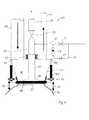
- the filling device 23 shown in FIGS. 6 to 10 has a through a hopper 25 formed filling head 11, on which a sack (bundle) 13th is attached.
- a Bag clamping device 19 e.g. an inflatable gasket pressed in from the outside, provided, which will be described in more detail below.
- an exhaust pipe 27 is provided in the funnel 25.
- the suction pipe 27 is with a pipe 29 connected, which with a vacuum source not shown in the figures, e.g. with a fan with exhaust air filter.
- a Shut-off device 31, e.g. a valve allows the suction pipe 27 opposite to seal the vacuum source airtight.
- the suction pipe 27 is axially displaceable relative to the pipe 29 arranged.
- a sliding tube or bellows 33 provided which connects the suction pipe 27 to the pipe 29. through a motor, hydraulic or pneumatic device, not shown the suction pipe 27 is adjustable in height. In the lowered state ( Figure 6) is the end of the suction tube 27 in the area of Outlet opening of the funnel 25.
- the suction pipe is 27 widened to a closure flap 35.
- the closure flap 35 has one Diameter which corresponds approximately to the outlet opening 37 of the funnel 25 and closes the filling head to the outside.
- a filling pipe 39 also opens into the funnel 25.
- the filling pipe 39 is connected via a Shut-off device with a storage container (neither in the figures shown) for a powdery or granular bulk material in connection.
- a storage container not in the figures shown
- the Filling tube 39 can be integrated known metering devices to the Dosing the amount of bulk material to be filled.
- a second opens Tube 41 in the funnel 25.
- the tube 41 serves as a gas suspension line and is connected to a filter system and / or the filling bunker. about the gas suspension line 41 becomes present in the atmosphere of the filling head Product returned to the filling bunker during the filling process.
- a vacuum source can be connected to the filter system.
- the gas suspension line 41 can also be used as a residual bag suction pipe 27 become.
- a line 45 is seen in the flow direction in front of the shut-off device 31 connected to the suction pipe 27. By means of a valve 47 can the line 45 are blocked.
- a bypass line 49 is before and after the valve 47 connected to the line 45. In the bypass line 49 is a valve 51 and a small flow meter 53 are provided.
- the lines 45 and 49 serve either the suction tube 27 during filling flush with a small gas stream or a new container 13 via line 39 inflate using a stronger gas flow.
- the bag clamping device 19 shown only schematically has one or several lifting cylinders 55, which have one end at the suspension points Support 57 on the filling device 23. The other end of the Lift cylinder engages the clamping ring 18.
- the lifting cylinders are in the axial direction (Arrow 61) adjustable in length.
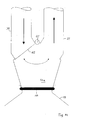
- Figures 7 to 10 show the individual steps in the filling of a Container 13 in detail.
- Figure 8 it can be seen that when closing the Container 13 has two clamps arranged a short distance apart 62a, 62b or container closures. The first pinch point 62a closes the container 13, the second clamping point 62b seals the container hose remaining on the filling head to the so-called Residual bag 63.
- a residual bag holding device can optionally be attached to the bag clamping device 19 64 may be provided.
- the remaining bag holding device 64 can be the remaining bag 63 clamp on the filling head 11, even if the clamping ring 18 already is solved.
- the second embodiment of a filling device has a filling head 11a, in which a filling pipe 39 and a suction pipe 27 lead.
- a movable, preferably provided in the filling head 11a pivotable flap 65 pivotable about a pivot axis 67. It is in the one end position, the filling pipe 39 (Fig. 11), and in the other end position the suction pipe 27 closed.
- the seal to the sack that is open on one side 13 and the change of containers can take place as shown in FIG. 6.
- the container 13 is prepared.
- the sack 13 or also the big bag is connected to the filling head 11 preferably by means of ring or funnel clamping or blah ring (FIG. 6).
- the container 13 consists of a gas-impermeable, flexible material.
- the container 13 is first evacuated as best as possible.
- the atmosphere is sucked off through the residual bag suction pipe 29 (FIG. 6) with the shut-off element 31 open to a filter system (dust removal).
- the shut-off device 31 is closed and then the container 13 is preferably inflated with an inerting gas (nitrogen, CO 2 , noble gas).
- the valve 47 remains open until the container 13 is filled with gas.
- the system is switched to rinsing.
- the valve 51 is opened and a small amount of air or inert gas flows continuously via the small flow meter 53 via the residual bag suction pipe 27 into the filling head 11.
- the lower part of the residual bag suction pipe 27 is also lifted by means of a lifting cylinder 55.
- the dosage from the filling bunker into the filling container 13 can, respectively, via the filling chute.
- Filling tube can be carried out with all known methods (squeeze tube, screw or swivel slide). It is advantageous if a gas oscillation is carried out via pipe 41 between the filling bunker and the filling container. However, this is not absolutely necessary, but prevents product losses in the direction of dedusting and thus reduces maintenance costs.
- the container 13 is closed with cable ties, bag closers or clamps at two spaced apart locations 62a, 62b in order to form two clamping locations 62a, 62b.
- the two pinch points 62a, 62b can also be two narrow weld seams or a single wide weld seam.
- the shut-off device 51 ininert gas flushing
- the container is prepared and the bag 13 is placed on the filling head (preferably Ring or funnel clamping) connected.
- the dosage of the Bulk material is now removed from the storage bunker with a not shown known metering device via filling pipe 39 into the filling container 13th
- the container 13 is fastened with cable ties, Bag closers, clamps twice to form two spaced apart arranged terminal points closed. Alternatively, you could a wide weld seam should be provided.
- the shut-off device 31 opens to the residual bag suction pipe 27 and at the same time closes the filling pipe 39. Now there is a slight negative pressure (vacuum) between the filling head 11a and the container 13 created so that the upper part of the bag (residual bag 63) is sucked in becomes.
- an additional residual bag holder 64 (see Figure 6) are activated, which holds the remaining bag on the filling head. Is the Residual bag holder 64 activated, the maximum generated by a blower Vacuum can be applied immediately.
- the sack 13 is cut through (separated).
- the full package 13 is now removed from the scales, a new container 13 is lowered the clamping ring 18 by means of lifting cylinder 55 and threading a new one Sacks prepared and put on hold, that is, immediately is now under the filling head 11a with the remaining bag 63 held an empty sack 13.
- the vacuum is via the residual sack suction tube 27 increased (the vacuum gets better), and the remaining bag 63 is over the Residual bag suction tube 27 e.g. sucked into a filter system or separation chamber.
- the blower output is now reduced again, to recirculation changed over, and the fresh container 13 finished to the filling head 11a connected.
- the device according to the invention thus ensures that when changing containers in a filling system with dusty or granular Bulk goods, such as fine chemicals or active substances that are low in dust he follows. This will contaminate the system, the filling container and pallets avoided, thereby cleaning them eliminated. In addition, contamination of the filling team or prevents possible cross-contamination with other chemicals.
- the filling head remains closed to the outside, since according to FIG. 6 the closure cap 35 of the residual bag suction tube 27 closes the filling head 11 or additionally as in FIG. 6, the residual bag 62a, 62b remains on the filling head until a new filling is started and the system is rendered inert remains. Adhesive product in the filling head does not have any external environmental influences exposed.
Landscapes
- Engineering & Computer Science (AREA)
- Mechanical Engineering (AREA)
- Basic Packing Technique (AREA)
Applications Claiming Priority (2)
| Application Number | Priority Date | Filing Date | Title |
|---|---|---|---|
| AT2012002 | 2002-02-08 | ||
| AT2012002 | 2002-02-08 |
Publications (1)
| Publication Number | Publication Date |
|---|---|
| EP1334908A1 true EP1334908A1 (fr) | 2003-08-13 |
Family
ID=27587159
Family Applications (1)
| Application Number | Title | Priority Date | Filing Date |
|---|---|---|---|
| EP03405066A Withdrawn EP1334908A1 (fr) | 2002-02-08 | 2003-02-07 | Dispositif et procédé pour remplir des matériaux en vrac |
Country Status (1)
| Country | Link |
|---|---|
| EP (1) | EP1334908A1 (fr) |
Cited By (7)
| Publication number | Priority date | Publication date | Assignee | Title |
|---|---|---|---|---|
| EP3041749B1 (fr) | 2013-09-02 | 2017-08-02 | Rubitec AG | Dispositif de transvasement de matière de processus entre un premier et un deuxième récipient et procédé correspondant |
| CN107839932A (zh) * | 2017-10-30 | 2018-03-27 | 无锡大东机械制造有限公司 | 夹袋称重装置及称重控制方法 |
| CN112357228A (zh) * | 2020-12-18 | 2021-02-12 | 湖北哈佛水泥机械有限公司 | 一种用于吨袋的伸缩灌装装置 |
| CN113291503A (zh) * | 2021-07-02 | 2021-08-24 | 上海威泽尔机械设备制造有限公司 | 一种吨袋自动罐装系统 |
| CN117225746A (zh) * | 2023-11-14 | 2023-12-15 | 乐山市奇能米业有限责任公司 | 一种大米生产用的筛分装置 |
| WO2024109385A1 (fr) * | 2022-11-22 | 2024-05-30 | 无锡理奇智能装备有限公司 | Appareil de serrage de sac, structure de scellement, machine d'ouverture de sac et procédé d'ouverture de sac |
| CN120716991A (zh) * | 2025-08-12 | 2025-09-30 | 常州吉烯石墨烯科技有限公司 | 石墨烯生产用研磨下料装置及其工作方法 |
Citations (1)
| Publication number | Priority date | Publication date | Assignee | Title |
|---|---|---|---|---|
| FR1370495A (fr) * | 1963-10-03 | 1964-08-21 | Dispositif d'ensachage supprimant tout contact du produit et de la capacité contenante avec l'air extérieur |
-
2003
- 2003-02-07 EP EP03405066A patent/EP1334908A1/fr not_active Withdrawn
Patent Citations (1)
| Publication number | Priority date | Publication date | Assignee | Title |
|---|---|---|---|---|
| FR1370495A (fr) * | 1963-10-03 | 1964-08-21 | Dispositif d'ensachage supprimant tout contact du produit et de la capacité contenante avec l'air extérieur |
Cited By (11)
| Publication number | Priority date | Publication date | Assignee | Title |
|---|---|---|---|---|
| EP3041749B1 (fr) | 2013-09-02 | 2017-08-02 | Rubitec AG | Dispositif de transvasement de matière de processus entre un premier et un deuxième récipient et procédé correspondant |
| US10167102B2 (en) | 2013-09-02 | 2019-01-01 | Rubitec Ag | Apparatus for transferring process material between a first container and a second container, and method for this purpose |
| US10800567B2 (en) | 2013-09-02 | 2020-10-13 | Rubitec Ag | Apparatus for transferring process material between a first container and a second container, and method for this purpose |
| CN107839932A (zh) * | 2017-10-30 | 2018-03-27 | 无锡大东机械制造有限公司 | 夹袋称重装置及称重控制方法 |
| CN112357228A (zh) * | 2020-12-18 | 2021-02-12 | 湖北哈佛水泥机械有限公司 | 一种用于吨袋的伸缩灌装装置 |
| CN113291503A (zh) * | 2021-07-02 | 2021-08-24 | 上海威泽尔机械设备制造有限公司 | 一种吨袋自动罐装系统 |
| WO2024109385A1 (fr) * | 2022-11-22 | 2024-05-30 | 无锡理奇智能装备有限公司 | Appareil de serrage de sac, structure de scellement, machine d'ouverture de sac et procédé d'ouverture de sac |
| CN117225746A (zh) * | 2023-11-14 | 2023-12-15 | 乐山市奇能米业有限责任公司 | 一种大米生产用的筛分装置 |
| CN117225746B (zh) * | 2023-11-14 | 2024-02-02 | 乐山市奇能米业有限责任公司 | 一种大米生产用的筛分装置 |
| CN120716991A (zh) * | 2025-08-12 | 2025-09-30 | 常州吉烯石墨烯科技有限公司 | 石墨烯生产用研磨下料装置及其工作方法 |
| CN120716991B (zh) * | 2025-08-12 | 2026-03-13 | 常州吉烯石墨烯科技有限公司 | 石墨烯生产用研磨下料装置及其工作方法 |
Similar Documents
| Publication | Publication Date | Title |
|---|---|---|
| EP0835829B1 (fr) | Dispositif de déchargement de sac de grande taille et méthode d'utilisation | |
| DE2235355A1 (de) | Vorrichtung zum sammeln von bohrstaub | |
| EP2049403B1 (fr) | Élément doseur sur un récipient pour des matériaux coulants ou en vrac | |
| DE102007038974B4 (de) | Vorrichtung zum kontaminationsfreien Abfüllen von Fliess- und Schüttgütern | |
| CH699603B1 (de) | Verfahren und Vorrichtung zum Umfüllen von Füllgut aus einem ersten Behälter in einen zweiten Behälter. | |
| DE69908750T2 (de) | Verfahren zum Entladen von Schüttgut aus einem Behälter und Einrichtung dafür | |
| EP4046926A1 (fr) | Dispositif de remplissage de matières en vrac d'un récipient dans un sac de récipient | |
| EP1334908A1 (fr) | Dispositif et procédé pour remplir des matériaux en vrac | |
| DE3220780A1 (de) | Vorrichtung zum befuellen von saecken mit fliess- bzw. rieselfoermigem, insbesondere staubfoermigem fuellgut | |
| EP1571088A1 (fr) | Procédé de remplissage et dispositif de préhension pour une machine de remplissage | |
| DE3726137C2 (fr) | ||
| DE102008014489A1 (de) | Behandlungseinrichtung und Verfahren zum Behandeln eines mit einem Schüttgut gefüllten offenen Sacks | |
| CH700400A2 (de) | Verfahren zur Durchführung eines Reinigungszyklus an einer Prozessanlage und Vorrichtung dazu. | |
| DE69106011T2 (de) | Pulverabgabevorrichtung. | |
| EP2285684B1 (fr) | Dispositif et procédé de déversement ou de soutirage sans contamination de matières en vrac | |
| EP0900164B1 (fr) | Procede et dispositif pour eviter l'emission de poussiere ou de gaz lors du transvasement avec des systemes doseurs de solides ou de liquides | |
| DE69705674T2 (de) | Entlade-Verfahren für Schüttgut von Behältern | |
| EP1890940B1 (fr) | Procede et dispositif pour vider avec de faibles emissions des substances contenues dans des grands sacs | |
| EP2125523A1 (fr) | Dispositif et procédé de transvasement sans contamination de poudres et de solides et nouvelle utilisation d'une feuille tubulaire pouvant être soudée et détachable | |
| DE3814337A1 (de) | Verfahren und vorrichtung zur befuellung eines kunststoffsacks | |
| DE3618981C2 (fr) | ||
| EP1145999B1 (fr) | Dispositif de remplissage d' un récipient, récipient et couvercle correspodantes | |
| CH692143A5 (de) | Verfahren und Vorrichtung zur Vermeidung von Produktestaub- oder Produktegasaustritt bei Abfüllung mit Feststoff- oder Flüssigkeitsdosiersystemen. | |
| DE3928452C2 (fr) | ||
| DE19808789B4 (de) | Schlauchbeutelmaschine |
Legal Events
| Date | Code | Title | Description |
|---|---|---|---|
| PUAI | Public reference made under article 153(3) epc to a published international application that has entered the european phase |
Free format text: ORIGINAL CODE: 0009012 |
|
| AK | Designated contracting states |
Designated state(s): AT BE BG CH CY CZ DE DK EE ES FI FR GB GR HU IE IT LI LU MC NL PT SE SI SK TR |
|
| AX | Request for extension of the european patent |
Extension state: AL LT LV MK RO |
|
| 17P | Request for examination filed |
Effective date: 20030919 |
|
| GRAP | Despatch of communication of intention to grant a patent |
Free format text: ORIGINAL CODE: EPIDOSNIGR1 |
|
| AKX | Designation fees paid |
Designated state(s): AT BE BG CH CY CZ DE DK EE ES FI FR GB GR HU IE IT LI LU MC NL PT SE SI SK TR |
|
| GRAS | Grant fee paid |
Free format text: ORIGINAL CODE: EPIDOSNIGR3 |
|
| STAA | Information on the status of an ep patent application or granted ep patent |
Free format text: STATUS: THE APPLICATION IS DEEMED TO BE WITHDRAWN |
|
| 18D | Application deemed to be withdrawn |
Effective date: 20040821 |