EP1336742A2 - Method for stimulating a lambda control loop - Google Patents
Method for stimulating a lambda control loop Download PDFInfo
- Publication number
- EP1336742A2 EP1336742A2 EP03002339A EP03002339A EP1336742A2 EP 1336742 A2 EP1336742 A2 EP 1336742A2 EP 03002339 A EP03002339 A EP 03002339A EP 03002339 A EP03002339 A EP 03002339A EP 1336742 A2 EP1336742 A2 EP 1336742A2
- Authority
- EP
- European Patent Office
- Prior art keywords
- amplitude
- frequency
- operating temperature
- lambda
- values
- Prior art date
- Legal status (The legal status is an assumption and is not a legal conclusion. Google has not performed a legal analysis and makes no representation as to the accuracy of the status listed.)
- Granted
Links
- 238000000034 method Methods 0.000 title claims abstract description 18
- 230000004936 stimulating effect Effects 0.000 title 1
- 230000005284 excitation Effects 0.000 claims description 33
- 238000002485 combustion reaction Methods 0.000 claims description 10
- 239000000498 cooling water Substances 0.000 claims description 4
- 230000000638 stimulation Effects 0.000 abstract description 9
- 230000001419 dependent effect Effects 0.000 abstract description 4
- 239000002826 coolant Substances 0.000 abstract 1
- 239000007789 gas Substances 0.000 description 12
- 239000000523 sample Substances 0.000 description 11
- 239000003054 catalyst Substances 0.000 description 10
- 238000004364 calculation method Methods 0.000 description 4
- 238000006243 chemical reaction Methods 0.000 description 4
- QVGXLLKOCUKJST-UHFFFAOYSA-N atomic oxygen Chemical compound [O] QVGXLLKOCUKJST-UHFFFAOYSA-N 0.000 description 3
- 239000001301 oxygen Substances 0.000 description 3
- 229910052760 oxygen Inorganic materials 0.000 description 3
- 230000006978 adaptation Effects 0.000 description 2
- 230000003197 catalytic effect Effects 0.000 description 2
- 238000011144 upstream manufacturing Methods 0.000 description 2
- 230000003321 amplification Effects 0.000 description 1
- 230000002950 deficient Effects 0.000 description 1
- 230000001627 detrimental effect Effects 0.000 description 1
- 238000003745 diagnosis Methods 0.000 description 1
- 238000010586 diagram Methods 0.000 description 1
- 239000000446 fuel Substances 0.000 description 1
- 230000007257 malfunction Effects 0.000 description 1
- 238000003199 nucleic acid amplification method Methods 0.000 description 1
- 230000000737 periodic effect Effects 0.000 description 1
- 239000010970 precious metal Substances 0.000 description 1
Images

Classifications
-
- F—MECHANICAL ENGINEERING; LIGHTING; HEATING; WEAPONS; BLASTING
- F02—COMBUSTION ENGINES; HOT-GAS OR COMBUSTION-PRODUCT ENGINE PLANTS
- F02D—CONTROLLING COMBUSTION ENGINES
- F02D41/00—Electrical control of supply of combustible mixture or its constituents
- F02D41/02—Circuit arrangements for generating control signals
- F02D41/14—Introducing closed-loop corrections
- F02D41/1438—Introducing closed-loop corrections using means for determining characteristics of the combustion gases; Sensors therefor
- F02D41/1493—Details
- F02D41/1495—Detection of abnormalities in the air/fuel ratio feedback system
-
- F—MECHANICAL ENGINEERING; LIGHTING; HEATING; WEAPONS; BLASTING
- F02—COMBUSTION ENGINES; HOT-GAS OR COMBUSTION-PRODUCT ENGINE PLANTS
- F02D—CONTROLLING COMBUSTION ENGINES
- F02D41/00—Electrical control of supply of combustible mixture or its constituents
- F02D41/02—Circuit arrangements for generating control signals
- F02D41/14—Introducing closed-loop corrections
- F02D41/1401—Introducing closed-loop corrections characterised by the control or regulation method
- F02D41/1408—Dithering techniques
-
- F—MECHANICAL ENGINEERING; LIGHTING; HEATING; WEAPONS; BLASTING
- F02—COMBUSTION ENGINES; HOT-GAS OR COMBUSTION-PRODUCT ENGINE PLANTS
- F02D—CONTROLLING COMBUSTION ENGINES
- F02D41/00—Electrical control of supply of combustible mixture or its constituents
- F02D41/02—Circuit arrangements for generating control signals
- F02D41/14—Introducing closed-loop corrections
- F02D41/1438—Introducing closed-loop corrections using means for determining characteristics of the combustion gases; Sensors therefor
- F02D41/1439—Introducing closed-loop corrections using means for determining characteristics of the combustion gases; Sensors therefor characterised by the position of the sensor
- F02D41/1441—Plural sensors
Definitions
- the invention relates to a method for positive excitation Lambda control with which an error in a lambda probe is detected becomes.
- a Diagnosed Lambda probe located upstream of a catalyst.
- the lambda probe to be diagnosed has a constant characteristic in its output signal.
- the lambda probe becomes a periodic lambda setpoint Forced excitation with a given frequency and amplitude superimposed.
- a model of the lambda control loop forms its line behavior, with one of the model parameters represents the sensor delay time. From the amplifications of the amplitudes, which are for the model and system for forced excitation result, the model values, especially the model value adapted for the sensor delay time.
- the lambda sensor is recognized as defective if the value for the change in the model parameter has a predetermined threshold exceeds. This means that if you are too strong Adaptation of the sensor delay time is a malfunction of the Lambda sensor is recognized. This way it can be continuous the functioning of the lambda probe in the lambda control circuit be checked.
- the stoichiometric setpoint for the air ratio is subjected to a positive excitation.
- the deviation from the stoichiometric setpoint alternately have a lean and fat shift.
- the oxygen storage of the catalyst is filled, O 2 is stored, while the catalyst is emptied again during the fat shift.
- This filling and emptying process depends on the setpoint shift (amplitude of the forced excitation) and the duration of the shift. It is known to carry out the forced stimulation in a time-based approach with the same amplitude and the same duration for fat and lean stimulation.
- the invention has for its object a method for Forced excitation of a lambda probe in an internal combustion engine provide that is not detrimental to exhaust emissions affects and a good exhaust gas conversion over wide operating areas ensures.
- the values for amplitude are selected and frequency of the forced excitation depending on an operating temperature the internal combustion engine.
- This solution of the invention The task is based on the knowledge that the known forced excitation for some operating conditions to a leads to poor conversion of the exhaust gases.
- By amplitude and frequency of the forced excitation adapted to the operating temperature are, according to the invention, also in low load and Idling range and increased exhaust emission values after a cold start avoided.
- the values for amplitude preferably depend and / or frequency of the forced excitation from the operating temperature of the cooling water. So far it is common for the Amplitude and frequency of the forced excitation relate to a cooling water temperature from 85 ° C.
- the values for amplitude and / or frequency can also be dependent the temperature of the cylinder head and / or the oil temperature be determined for the forced excitation. Prefers In addition to the operating temperature, the air mass and the speed of predetermined temperature values is taken into account.
- the one from the internal combustion engine 10 leaked air is in through an exhaust tract 14 in a three-way catalyst 16 passed.
- a first oxygen probe 18 is provided for catalytic converter 16, whose output signal steadily depends on the air ratio lambda in the Exhaust gas flow depends.
- the oxygen sensors are also called Called lambda sensors.
- a second lambda probe 20 is arranged which measures the catalyst efficiency checked and as a linear probe or one so-called jump probe can be formed.
- the signals from the lambda probes 18 and 20 are sent to a lambda control device 22 forwarded from the two delivered signals on the efficiency of the catalyst 16 and thus concludes the conversion of the exhaust gases.
- the lambda control device determines a desired lambda value as a manipulated variable and passes this on to the engine control 24. Furthermore, the lambda control device can be a model for the behavior of the control system.
- the model includes, as a model parameter, the sensor delay time. As known from DE 195 16 239 C2, has the transfer function the lambda control system behaves like series connection two first order delay elements and a dead time link. To make as little change as possible to maintain the exhaust emission during the forced excitation Frequency and amplitude depending on speed and load as well the operating temperature of the internal combustion engine.
- the lambda setpoint fluctuates with the known forced excitation around the mean 26 at which stoichiometric combustion he follows.
- the forced excitation can be in a fat part 28 and a lean part 30 can be divided.
- the amplitudes 32 and 34 of each suggestion are the same size. Own as well the lean and the fat half-wave 28 and 30 respectively same duration 36 or 38.
- the lambda setpoint is set at 0.998 to reduce the risk of NOx breakthroughs.
- the forced excitation according to the invention has a lean half-wave 40 with a duration t lean 42 and an amplitude A lean 44.
- a fat half-wave 46 follows the lean half-wave 40.
- the bold half-wave 46 has a duration t bold 48 and an amplitude A bold 50.
- the four parameters characterizing the forced excitation: t lean , A lean , t rich , A rich can be selected independently of one another.
- a first characteristic map 52 determines the values for a first frequency and a first amplitude as a function of speed and load.
- the frequency is defined as an inverse period, the period being the time period of a defined exhaust gas sequence of lean and rich exhaust gas packages, which is repeated regularly under steady-state operating conditions (ie with the same amount of exhaust gas per time and the same exhaust gas composition).
- Lean / rich amplitude is understood to mean the lambda values of individual exhaust gas packets of the exhaust gas packet sequence.
- the map 52 determines the frequency and amplitude for a first temperature T 1 .
- the map 54 determines the values for a second frequency and a second amplitude depending on the speed and load.
- the tuples of frequency and amplitude are forwarded to a calculation unit 56.
- the calculation unit 56 determines the tuple of nominal values for frequency and amplitude 60 by means of a linear or a non-linear interpolation.
- the calculation method shown in FIG. 4 can also be carried out by a three-dimensional map can be replaced.
- the method according to the invention shows particular advantages operating temperature-dependent forced excitation also related in a so-called electronic thermal management, at which the operating temperature of the engine with the aim of a low fuel consumption and good exhaust gas values is varied.
- thermal management works through a targeted adaptation of the forced control to the operating temperature supported.
- the limit with which to change the model parameter selected in a preferred embodiment also depends on the operating temperature.
- the Limit value of the speed and the load of the internal combustion engine depend.
- a square wave or a sinusoidal vibration can be used. Is also it is possible to use excitation with a sawtooth To provide vibration or another excitation pattern.
- the sawtooth-shaped vibration is by amplitude, frequency and Marked rise time.
- the rise time can also be the inventive method depending on the operating temperature to get voted.
Landscapes
- Engineering & Computer Science (AREA)
- Chemical & Material Sciences (AREA)
- Combustion & Propulsion (AREA)
- Mechanical Engineering (AREA)
- General Engineering & Computer Science (AREA)
- Electrical Control Of Air Or Fuel Supplied To Internal-Combustion Engine (AREA)
- Exhaust Gas After Treatment (AREA)
Abstract
Description
Die Erfindung betrifft ein Verfahren zur Zwangsanregung einer Lambdaregelung, mit dem ein Fehler bei einer Lambdasonde erkannt wird.The invention relates to a method for positive excitation Lambda control with which an error in a lambda probe is detected becomes.
Aus DE 198 44 994 A1 ist ein Verfahren zur Diagnose einer Lambdasonde bekannt. Bei dem bekannten Verfahren wird eine stromaufwärts eines Katalysators angeordnete Lambdasonde diagnostiziert. Die zu diagnostizierende Lambdasonde besitzt eine in ihrem Ausgangssignal stetige Charakteristik. Zur Diagnose der Lambdasonde wird zu einem Lambda-Sollwert eine periodische Zwangsanregung mit vorgegebener Frequenz und Amplitude überlagert. Ein Modell des Lambdaregelungskreises bildet dessen Streckenverhalten ab, wobei einer der Modellparameter die Sensorverzögerungszeit darstellt. Aus den Amplitudenverstärkungen, die sich für Modell und System bei der Zwangsanregung ergeben, werden die Modellwerte, insbesondere der Modellwert für die Sensorverzögerungszeit adaptiert. Die Lambdasonde wird hierbei als defekt erkannt, wenn der Wert für die Änderung des Modellparameters einen vorgegebenen Schwellenwert überschreitet. Dies bedeutet, dass bei einer zu starken Adaption der Sensorverzögerungszeit eine Störung der Lambdasonde erkannt wird. Auf diese Weise kann kontinuierlich die Funktionsweise der Lambdasonde in dem Lambdareglungskreis überprüft werden.DE 198 44 994 A1 describes a method for diagnosing a Lambda sensor known. In the known method, a Diagnosed Lambda probe located upstream of a catalyst. The lambda probe to be diagnosed has a constant characteristic in its output signal. For diagnosis the lambda probe becomes a periodic lambda setpoint Forced excitation with a given frequency and amplitude superimposed. A model of the lambda control loop forms its line behavior, with one of the model parameters represents the sensor delay time. From the amplifications of the amplitudes, which are for the model and system for forced excitation result, the model values, especially the model value adapted for the sensor delay time. The lambda sensor is recognized as defective if the value for the change in the model parameter has a predetermined threshold exceeds. This means that if you are too strong Adaptation of the sensor delay time is a malfunction of the Lambda sensor is recognized. This way it can be continuous the functioning of the lambda probe in the lambda control circuit be checked.
Neben dem vorstehenden spezifischen Einsatz der Zwangsanregung kann diese vorrangig zur Steigerung des Wirkungsgrades eines Dreiwegekatalysators eingesetzt werden, wie beispielsweise in DE 43 44 892 C2 beschrieben. Hierbei wird für die lineare Lambdaregelung der stöchiometrische Sollwert für die Luftzahl mit einer Zwangsanregung beaufschlagt. Die Abweichung von dem stöchiometrischen Sollwert besitzen abwechselnd eine Mager- und Fettverschiebung. Bei der Magerverschiebung wird der Sauerstoffspeicher des Katalysators gefüllt, es wird O2 eingelagert, während bei der Fettverschiebung der Katalysator wieder geleert wird. Dieser Füll- und Leervorgang ist abhängig von der Sollwertverschiebung (Amplitude der Zwangsanregung) und der Dauer der Verschiebung. Es ist bekannt, die Zwangsanregung in einem zeitbasierten Ansatz mit gleicher Amplitude und gleicher Dauer für Fett- und Mageranregung durchzuführen.In addition to the above-mentioned specific use of forced excitation, this can primarily be used to increase the efficiency of a three-way catalytic converter, as described for example in DE 43 44 892 C2. For the linear lambda control, the stoichiometric setpoint for the air ratio is subjected to a positive excitation. The deviation from the stoichiometric setpoint alternately have a lean and fat shift. During the lean shift, the oxygen storage of the catalyst is filled, O 2 is stored, while the catalyst is emptied again during the fat shift. This filling and emptying process depends on the setpoint shift (amplitude of the forced excitation) and the duration of the shift. It is known to carry out the forced stimulation in a time-based approach with the same amplitude and the same duration for fat and lean stimulation.
Als nachteilig an der bisherigen rein last- und drehzahlabhängigen Zwangsanregung, auch als forced stimulation bezeichnet, hat sich herausgestellt, dass durch die Änderung der Lambda-Sollwerte es zu einer erhöhten Abgasemission kommt, dies insbesondere bei Katalysatoren, die über längere Zeit benutzt worden sind, oder bei Katalysatoren mit geringer Edelmetallbeladung.As a disadvantage of the previous purely load and speed dependent Forced stimulation, also called forced stimulation, has been shown to change the Lambda setpoints there is an increased exhaust emission, this is particularly the case with catalysts that are used over a long period of time have been used, or for catalysts with low precious metal loading.
Der Erfindung liegt die Aufgabe zugrunde, ein Verfahren zur Zwangsanregung einer Lambdasonde in einer Brennkraftmaschine bereitzustellen, das sich nicht nachteilig auf die Abgasemission auswirkt und über weite Betriebsbereiche eine gute Abgaskonvertierung sicherstellt.The invention has for its object a method for Forced excitation of a lambda probe in an internal combustion engine provide that is not detrimental to exhaust emissions affects and a good exhaust gas conversion over wide operating areas ensures.
Erfindungsgemäß wird die Aufgabe durch ein Verfahren mit den
Merkmalen aus Anspruch 1 gelöst. Vorteilhafte Ausgestaltungen
bilden den Gegenstand der Unteransprüche.According to the invention, the object is achieved by a method with the
Features solved from
Gemäß Anspruch 1 erfolgt die Auswahl der Werte für Amplitude
und Frequenz der Zwangsanregung abhängig von einer Betriebstemperatur
der Brennkraftmaschine. Dieser Lösung der erfindungsgemäßen
Aufgabe liegt die Erkenntnis zugrunde, dass die
bekannte Zwangsanregung für einige Betriebszustände zu einer
schlechten Konvertierung der Abgase führt. Indem Amplitude
und Frequenz der Zwangsanregung an die Betriebstemperatur angepasst
sind, werden erfindungsgemäß auch im Niedriglast- und
Leerlaufbereich sowie nach einem Kaltstart erhöhte Abgasemissionswerte
vermieden. Bevorzugt hängen die Werte für Amplitude
und/oder Frequenz der Zwangsanregung von der Betriebstemperatur
des Kühlwassers ab. Bisher ist es üblich, dass die
Amplitude und Frequenz der Zwangsanregung sich auf eine Kühlwassertemperatur
von 85°C beziehen. Weicht die Temperatur des
Kühlwassers hiervon ab, ergeben sich deutlich andere Konvertierungsraten
für den Katalysator und mithin ein anderes Verhalten
des geschlossenen Lambdaregelkreises. Um eine wirkungsvolle
Zwangsanregung in dem Lambdaregelkreis durchzuführen,
ohne eine zusätzliche Erhöhung der Abgasemission zu erzielen,
werden Frequenz und Amplitude an den geänderten Lambdaregelkreis
angepasst.According to
Die Werte für Amplitude und/oder Frequenz können auch abhängig von der Temperatur des Zylinderkopfs und/oder der Öltemperatur für die Zwangsanregung bestimmt werden. Bevorzugt werden neben der Betriebstemperatur auch die Luftmasse und die Drehzahl vorbestimmter Temperaturwerte berücksichtigt.The values for amplitude and / or frequency can also be dependent the temperature of the cylinder head and / or the oil temperature be determined for the forced excitation. Prefers In addition to the operating temperature, the air mass and the speed of predetermined temperature values is taken into account.
Ein bevorzugtes Ausführungsbeispiel der erfindungsgemäßen Zwangsanregung wird anhand der nachfolgenden Figuren näher erläutert. Es zeigt:
- Fig. 1
- schematische Ansicht einer Brennkraftmaschine mit Abgassystem,
- Fig. 2
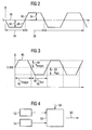
- Verlauf einer Zwangsanregung nach dem Stand der Technik,
- Fig. 3
- eine erfindungsgemäße Zwangsanregung und
- Fig. 4
- Berechnung von Frequenz und Amplitudensollwerten.
- Fig. 1
- schematic view of an internal combustion engine with exhaust system,
- Fig. 2
- Course of a forced stimulation according to the prior art,
- Fig. 3
- a forced stimulation according to the invention and
- Fig. 4
- Calculation of frequency and amplitude setpoints.
Das erfindungsgemäße Verfahren zur Zwangsanregung wird nachfolgend
anhand von Figur 1 näher erläutert. Eine schematisch
dargestellte Brennkraftmaschine 10 saugt über einen Ansaugtrakt
12 in Pfeilrichtung Luft an. Die aus der Brennkraftmaschine
10 ausgetretene Luft wird über einen Abgastrakt 14 in
einen Dreiwegekatalysator 16 geleitet. Stromaufwärts von dem
Katalysator 16 ist eine erste Sauerstoffsonde 18 vorgesehen,
deren Ausgangssignal stetig von der Luftzahl Lambda in dem
Abgasstrom abhängt. Die Sauerstoffsensoren werden auch als
Lambdasonden bezeichnet. Stromabwärts von dem Katalysator 16
ist eine zweite Lambdasonde 20 angeordnet, die den Katalysatorwirkungsgrad
überprüft und als eine lineare Sonde oder eine
sogenannte Sprungsonde ausgebildet sein kann.The method of forced excitation according to the invention is as follows
explained with reference to Figure 1. A schematic
Die Signale der Lambdasonden 18 und 20 werden an eine Lambdaregelungseinrichtung
22 weitergeleitet, die aus den beiden
gelieferten Signalen auf den Wirkungsgrad des Katalysators 16
und damit auf die Konvertierung der Abgase schließt.The signals from the
Die Lambdaregelungseinrichtung bestimmt einen Lambda-Sollwert
als Stellgröße und gibt diesen an die Motorsteuerung 24 weiter.
Ferner kann die Lambdaregelungseinrichtung ein Modell
für das Verhalten der Regelungsstrecke besitzen. Das Modell
beinhaltet, als einen Modellparameter die Sensorverzögerungszeit.
Wie aus DE 195 16 239 C2 bekannt, hat die Übertragungsfunktion
der Lambdaregelstrecke ein Verhalten wie das Hintereinanderschalten
zweier Verzögerungsglieder erster Ordnung
und einem Totzeitglied. Um eine möglichst geringe Änderung
der Abgasemission bei der Zwangsanregung zu erhalten, werden
Frequenz und Amplitude abhängig von Drehzahl und Last sowie
der Betriebstemperatur der Brennkraftmaschine festgelegt.The lambda control device determines a desired lambda value
as a manipulated variable and passes this on to the
In Fig. 2 ist der Lambda-Sollwert über die Zeit dargestellt.
Der Lambda-Sollwert schwankt bei der bekannten Zwangsanregung
um den Mittelwert 26, bei dem stöchiometrische Verbrennung
erfolgt. Die Zwangsanregung kann in einen fetten Teil 28 und
einen mageren Teil 30 unterteilt werden. Die Amplituden 32
und 34 der jeweiligen Anregung sind gleich groß. Ebenso besitzen
die magere und die fette Halbwelle 28 bzw. 30 die
gleiche Dauer 36 bzw. 38. 2 shows the lambda setpoint over time.
The lambda setpoint fluctuates with the known forced excitation
around the mean 26 at which stoichiometric combustion
he follows. The forced excitation can be in a
Fig. 3 zeigt beispielhaft die Lambda-Sollwerte bei der erfindungsgemäßen
Zwangsanregung. Der Lambda-Sollwert ist hierbei
zu 0,998 vorgegeben, um die Gefahr von NOx-Durchbrüchen zu
verringern. Die erfindungsgemäße Zwangsanregung besitzt eine
magere Halbwelle 40, mit einer Dauer tmager 42 und eine Amplitude
Amager 44.3 shows an example of the lambda target values in the case of the forced excitation according to the invention. The lambda setpoint is set at 0.998 to reduce the risk of NOx breakthroughs. The forced excitation according to the invention has a lean half-
An die magere Halbwelle 40 schließt sich eine fette Halbwelle
46 an. Die fette Halbwelle 46 besitzt eine Dauer tfett 48 und
eine Amplitude Afett 50. Bei der erfindungsgemäßen Zwangsanregung
können die vier die Zwangsanregung charakterisierenden
Parameter: tmager, Amager, tfett, Afett unabhängig voneinander gewählt
werden.A fat half-
Die Bestimmung der Parameter wird an einem Blockschaltbild zu
Fig. 4 verdeutlicht. Ein erstes Kennfeld 52 bestimmt abhängig
von Drehzahl und Last die Werte für eine erste Frequenz und
eine erste Amplitude. Die Frequenz ist als inverse Periodendauer
definiert, wobei die Periodendauer der Zeitabschnitt
einer definierten Abgaspaketfolge von mageren und fetten Abgaspaketen
ist, die sich bei stationären Betriebsbedingungen
(d.h. bei gleicher Abgasmenge pro Zeit und gleiche Abgaszusammensetzung)
regelmäßig wiederholt. Unter Mager-/Fett-Amplitude
werden die Lambdawerte von einzelnen Abgaspaketen
der Abgaspaketfolge verstanden. Das Kennfeld 52 bestimmt Frequenz
und Amplitude für eine erste Temperatur T1. Das Kennfeld
54 bestimmt abhängig von Drehzahl und Last die Werte für
eine zweite Frequenz und eine zweite Amplitude. Die Tupel aus
Frequenz und Amplitude werden an eine Berechnungseinheit 56
weitergeleitet. Die Berechnungseinheit 56 bestimmt abhängig
von dem Istwert 58 für die Betriebstemperatur durch eine lineare
oder eine nicht lineare Interpolation das Tupel von
Sollwerten für Frequenz und Amplitude 60.The determination of the parameters is illustrated on a block diagram of FIG. 4. A first
Die in Fig. 4 gezeigte Berechnungsweise kann ebenfalls durch ein dreidimensionales Kennfeld ersetzt werden. The calculation method shown in FIG. 4 can also be carried out by a three-dimensional map can be replaced.
Besondere Vorzüge zeigt das erfindungsgemäße Verfahren der betriebstemperaturabhängigen Zwangsanregung auch im Zusammenhang bei einem sogenannten elektronischen Thermomanagement, bei dem die Betriebstemperatur des Motors mit dem Ziel eines geringen Kraftstoffverbrauchs und guter Abgaswerte gezielt variiert wird. Die Wirkungsweise des Thermomanagements wird durch eine gezielte Anpassung der Zwangsregelung an die Betriebstemperatur unterstützt.The method according to the invention shows particular advantages operating temperature-dependent forced excitation also related in a so-called electronic thermal management, at which the operating temperature of the engine with the aim of a low fuel consumption and good exhaust gas values is varied. The way thermal management works through a targeted adaptation of the forced control to the operating temperature supported.
Der Grenzwert, mit dem die Änderung des Modellparameters gewählt wird, hängt in einer bevorzugten Ausgestaltung ebenfalls von der Betriebstemperatur ab. Zusätzlich kann der Grenzwert von der Drehzahl und der Last der Brennkraftmaschine abhängen.The limit with which to change the model parameter selected in a preferred embodiment also depends on the operating temperature. In addition, the Limit value of the speed and the load of the internal combustion engine depend.
Für die Zwangsanregung können eine Rechteckschwingung oder eine sinusförmige Schwingung eingesetzt werden. Ebenfalls ist es möglich eine Zwangsanregung mit einer sägezahnförmigen Schwingung oder einem anderem Anregungsmuster vorzusehen. Die sägezahförmige Schwingung ist durch Amplitude, Frequenz und Anstiegszeit gekennzeichnet. Auch die Anstiegszeit kann bei dem erfindungsgemäßen Verfahren abhängig von der Betriebstemperatur gewählt werden.A square wave or a sinusoidal vibration can be used. Is also it is possible to use excitation with a sawtooth To provide vibration or another excitation pattern. The sawtooth-shaped vibration is by amplitude, frequency and Marked rise time. The rise time can also be the inventive method depending on the operating temperature to get voted.
Claims (6)
Applications Claiming Priority (2)
| Application Number | Priority Date | Filing Date | Title |
|---|---|---|---|
| DE2002106675 DE10206675C1 (en) | 2002-02-18 | 2002-02-18 | Forced stimulation method for lambda regulation for IC engine with catalyzer has forced stimulation parameters matched to engine operating temperature |
| DE10206675 | 2002-02-18 |
Publications (3)
| Publication Number | Publication Date |
|---|---|
| EP1336742A2 true EP1336742A2 (en) | 2003-08-20 |
| EP1336742A3 EP1336742A3 (en) | 2006-03-15 |
| EP1336742B1 EP1336742B1 (en) | 2006-12-20 |
Family
ID=7713850
Family Applications (1)
| Application Number | Title | Priority Date | Filing Date |
|---|---|---|---|
| EP20030002339 Expired - Lifetime EP1336742B1 (en) | 2002-02-18 | 2003-02-03 | Method for stimulating a lambda control loop |
Country Status (2)
| Country | Link |
|---|---|
| EP (1) | EP1336742B1 (en) |
| DE (2) | DE10206675C1 (en) |
Families Citing this family (5)
| Publication number | Priority date | Publication date | Assignee | Title |
|---|---|---|---|---|
| WO2004085819A1 (en) | 2003-03-26 | 2004-10-07 | Mitsubishi Jidosha Kogyo Kabushiki Kaisha | Exhaust emission control device of internal combustion engine |
| DE10358900A1 (en) * | 2003-12-16 | 2005-07-21 | Volkswagen Ag | Method for operating an internal combustion engine with continuous lambda control |
| DE102004038481B3 (en) * | 2004-08-07 | 2005-07-07 | Audi Ag | Regulation method for air/fuel ratio for automobile engine with exhaust catalyzer providing forced modulation of filling level of oxygen reservoir within catalyzer |
| US7793489B2 (en) * | 2005-06-03 | 2010-09-14 | Gm Global Technology Operations, Inc. | Fuel control for robust detection of catalytic converter oxygen storage capacity |
| DE102021120527A1 (en) | 2021-08-06 | 2023-02-09 | Ford Global Technologies, Llc | Method for controlling a gas-powered internal combustion engine |
Citations (2)
| Publication number | Priority date | Publication date | Assignee | Title |
|---|---|---|---|---|
| DE4344892C2 (en) | 1992-12-29 | 1998-04-23 | Honda Motor Co Ltd | Air-fuel ratio control device for an internal combustion engine |
| DE19844994A1 (en) | 1998-09-30 | 2000-04-06 | Siemens Ag | Continuous lambda probe diagnosis method |
Family Cites Families (2)
| Publication number | Priority date | Publication date | Assignee | Title |
|---|---|---|---|---|
| US5325664A (en) * | 1991-10-18 | 1994-07-05 | Honda Giken Kogyo Kabushiki Kaisha | System for determining deterioration of catalysts of internal combustion engines |
| DE19744410C2 (en) * | 1997-10-08 | 2001-06-21 | Ford Global Tech Inc | Method for monitoring the smooth running control of an internal combustion engine |
-
2002
- 2002-02-18 DE DE2002106675 patent/DE10206675C1/en not_active Expired - Fee Related
-
2003
- 2003-02-03 EP EP20030002339 patent/EP1336742B1/en not_active Expired - Lifetime
- 2003-02-03 DE DE50306001T patent/DE50306001D1/en not_active Expired - Lifetime
Patent Citations (2)
| Publication number | Priority date | Publication date | Assignee | Title |
|---|---|---|---|---|
| DE4344892C2 (en) | 1992-12-29 | 1998-04-23 | Honda Motor Co Ltd | Air-fuel ratio control device for an internal combustion engine |
| DE19844994A1 (en) | 1998-09-30 | 2000-04-06 | Siemens Ag | Continuous lambda probe diagnosis method |
Also Published As
| Publication number | Publication date |
|---|---|
| EP1336742A3 (en) | 2006-03-15 |
| DE10206675C1 (en) | 2003-05-22 |
| DE50306001D1 (en) | 2007-02-01 |
| EP1336742B1 (en) | 2006-12-20 |
Similar Documents
| Publication | Publication Date | Title |
|---|---|---|
| EP1024254B1 (en) | Method and apparatus for controlling an exhaust gas after-treatment system | |
| DE112007000322B4 (en) | Exhaust system for an internal combustion engine | |
| DE69202163T2 (en) | Exhaust gas detoxification system for an internal combustion engine. | |
| DE10022981B4 (en) | Emission Control System | |
| DE10224601B4 (en) | Method and control device for controlling the operation of an internal combustion engine | |
| DE102007025377B4 (en) | Air / fuel ratio control device for an internal combustion engine | |
| DE60029893T2 (en) | Air-fuel ratio controller for multi-cylinder internal combustion engine | |
| DE19953601A1 (en) | Method for checking an exhaust gas catalytic converter of an internal combustion engine | |
| DE19539024C2 (en) | Diagnostic device for detecting catalytic converter damage to a catalytic converter arranged in the exhaust pipe of an internal combustion engine | |
| DE19839791B4 (en) | Air-fuel ratio control for an internal combustion engine | |
| DE4219134A1 (en) | AIR / FUEL RATIO CONTROL UNIT FOR A MACHINE | |
| DE112012006716T5 (en) | Control device for internal combustion engine | |
| DE19545924B4 (en) | Methods and apparatus for controlling air / fuel ratio learning of an internal combustion engine | |
| DE19851843B4 (en) | A process for sulfate regeneration of a NOx storage catalyst for a lean-burn engine | |
| DE3821357A1 (en) | METHOD AND DEVICE FOR LAMB CONTROL WITH SEVERAL PROBES | |
| DE19926146A1 (en) | Method for initiating and monitoring desulfurization of at least one NOx storage catalytic converter arranged in an exhaust gas duct of an internal combustion engine | |
| EP1336742B1 (en) | Method for stimulating a lambda control loop | |
| DE19935968B4 (en) | Control unit for the air / fuel ratio of an engine | |
| DE19547646A1 (en) | Method of controlling an IC engine | |
| DE3540420C2 (en) | ||
| DE69606533T2 (en) | AIR FUEL MODULATION RATIO | |
| DE102018133185A1 (en) | EXHAUST GAS CLEANING DEVICE FOR A COMBUSTION ENGINE | |
| DE102018133184A1 (en) | EXHAUST GAS CLEANING DEVICE FOR A COMBUSTION ENGINE | |
| EP1255922B1 (en) | Device and method for controlling operation of a multi-cylinder engine for motor vehicles having a multi-flow emission control system | |
| DE10023072B4 (en) | Method and device for determining a NOx concentration of an exhaust gas stream of an internal combustion engine |
Legal Events
| Date | Code | Title | Description |
|---|---|---|---|
| PUAI | Public reference made under article 153(3) epc to a published international application that has entered the european phase |
Free format text: ORIGINAL CODE: 0009012 |
|
| AK | Designated contracting states |
Designated state(s): AT BE BG CH CY CZ DE DK EE ES FI FR GB GR HU IE IT LI LU MC NL PT SE SI SK TR |
|
| AX | Request for extension of the european patent |
Extension state: AL LT LV MK RO |
|
| PUAL | Search report despatched |
Free format text: ORIGINAL CODE: 0009013 |
|
| AK | Designated contracting states |
Kind code of ref document: A3 Designated state(s): AT BE BG CH CY CZ DE DK EE ES FI FR GB GR HU IE IT LI LU MC NL PT SE SI SK TR |
|
| AX | Request for extension of the european patent |
Extension state: AL LT LV MK RO |
|
| 17P | Request for examination filed |
Effective date: 20060206 |
|
| GRAP | Despatch of communication of intention to grant a patent |
Free format text: ORIGINAL CODE: EPIDOSNIGR1 |
|
| GRAS | Grant fee paid |
Free format text: ORIGINAL CODE: EPIDOSNIGR3 |
|
| GRAA | (expected) grant |
Free format text: ORIGINAL CODE: 0009210 |
|
| AKX | Designation fees paid |
Designated state(s): DE FR GB IT |
|
| AK | Designated contracting states |
Kind code of ref document: B1 Designated state(s): DE FR GB IT |
|
| REG | Reference to a national code |
Ref country code: GB Ref legal event code: FG4D Free format text: NOT ENGLISH |
|
| GBT | Gb: translation of ep patent filed (gb section 77(6)(a)/1977) |
Effective date: 20070110 |
|
| REF | Corresponds to: |
Ref document number: 50306001 Country of ref document: DE Date of ref document: 20070201 Kind code of ref document: P |
|
| ET | Fr: translation filed | ||
| PLBE | No opposition filed within time limit |
Free format text: ORIGINAL CODE: 0009261 |
|
| STAA | Information on the status of an ep patent application or granted ep patent |
Free format text: STATUS: NO OPPOSITION FILED WITHIN TIME LIMIT |
|
| 26N | No opposition filed |
Effective date: 20070921 |
|
| PGFP | Annual fee paid to national office [announced via postgrant information from national office to epo] |
Ref country code: GB Payment date: 20090219 Year of fee payment: 7 |
|
| PGFP | Annual fee paid to national office [announced via postgrant information from national office to epo] |
Ref country code: IT Payment date: 20090220 Year of fee payment: 7 |
|
| PGFP | Annual fee paid to national office [announced via postgrant information from national office to epo] |
Ref country code: FR Payment date: 20090213 Year of fee payment: 7 |
|
| GBPC | Gb: european patent ceased through non-payment of renewal fee |
Effective date: 20100203 |
|
| REG | Reference to a national code |
Ref country code: FR Ref legal event code: ST Effective date: 20101029 |
|
| PG25 | Lapsed in a contracting state [announced via postgrant information from national office to epo] |
Ref country code: FR Free format text: LAPSE BECAUSE OF NON-PAYMENT OF DUE FEES Effective date: 20100301 |
|
| PG25 | Lapsed in a contracting state [announced via postgrant information from national office to epo] |
Ref country code: GB Free format text: LAPSE BECAUSE OF NON-PAYMENT OF DUE FEES Effective date: 20100203 Ref country code: IT Free format text: LAPSE BECAUSE OF NON-PAYMENT OF DUE FEES Effective date: 20100203 |
|
| PGFP | Annual fee paid to national office [announced via postgrant information from national office to epo] |
Ref country code: DE Payment date: 20200229 Year of fee payment: 18 |
|
| REG | Reference to a national code |
Ref country code: DE Ref legal event code: R084 Ref document number: 50306001 Country of ref document: DE |
|
| REG | Reference to a national code |
Ref country code: DE Ref legal event code: R081 Ref document number: 50306001 Country of ref document: DE Owner name: VITESCO TECHNOLOGIES GMBH, DE Free format text: FORMER OWNER: CONTINENTAL AUTOMOTIVE GMBH, 30165 HANNOVER, DE |
|
| REG | Reference to a national code |
Ref country code: DE Ref legal event code: R119 Ref document number: 50306001 Country of ref document: DE |
|
| PG25 | Lapsed in a contracting state [announced via postgrant information from national office to epo] |
Ref country code: DE Free format text: LAPSE BECAUSE OF NON-PAYMENT OF DUE FEES Effective date: 20210901 |