EP1337983B1 - Distributeur automatique - Google Patents
Distributeur automatique Download PDFInfo
- Publication number
- EP1337983B1 EP1337983B1 EP01980560A EP01980560A EP1337983B1 EP 1337983 B1 EP1337983 B1 EP 1337983B1 EP 01980560 A EP01980560 A EP 01980560A EP 01980560 A EP01980560 A EP 01980560A EP 1337983 B1 EP1337983 B1 EP 1337983B1
- Authority
- EP
- European Patent Office
- Prior art keywords
- belt
- goods
- vertical
- horizontal
- delivery
- Prior art date
- Legal status (The legal status is an assumption and is not a legal conclusion. Google has not performed a legal analysis and makes no representation as to the accuracy of the status listed.)
- Expired - Lifetime
Links
Images


Classifications
-
- G—PHYSICS
- G07—CHECKING-DEVICES
- G07F—COIN-FREED OR LIKE APPARATUS
- G07F11/00—Coin-freed apparatus for dispensing, or the like, discrete articles
- G07F11/02—Coin-freed apparatus for dispensing, or the like, discrete articles from non-movable magazines
- G07F11/04—Coin-freed apparatus for dispensing, or the like, discrete articles from non-movable magazines in which magazines the articles are stored one vertically above the other
- G07F11/16—Delivery means
- G07F11/165—Delivery means using xyz-picker or multi-dimensional article picking arrangements
-
- G—PHYSICS
- G07—CHECKING-DEVICES
- G07F—COIN-FREED OR LIKE APPARATUS
- G07F11/00—Coin-freed apparatus for dispensing, or the like, discrete articles
- G07F11/02—Coin-freed apparatus for dispensing, or the like, discrete articles from non-movable magazines
- G07F11/04—Coin-freed apparatus for dispensing, or the like, discrete articles from non-movable magazines in which magazines the articles are stored one vertically above the other
- G07F11/10—Coin-freed apparatus for dispensing, or the like, discrete articles from non-movable magazines in which magazines the articles are stored one vertically above the other two or more magazines having a common delivery chute
-
- G—PHYSICS
- G07—CHECKING-DEVICES
- G07F—COIN-FREED OR LIKE APPARATUS
- G07F11/00—Coin-freed apparatus for dispensing, or the like, discrete articles
- G07F11/02—Coin-freed apparatus for dispensing, or the like, discrete articles from non-movable magazines
- G07F11/04—Coin-freed apparatus for dispensing, or the like, discrete articles from non-movable magazines in which magazines the articles are stored one vertically above the other
- G07F11/16—Delivery means
- G07F11/163—Delivery means characterised by blocking access to the output bins
-
- G—PHYSICS
- G07—CHECKING-DEVICES
- G07F—COIN-FREED OR LIKE APPARATUS
- G07F11/00—Coin-freed apparatus for dispensing, or the like, discrete articles
- G07F11/02—Coin-freed apparatus for dispensing, or the like, discrete articles from non-movable magazines
- G07F11/38—Coin-freed apparatus for dispensing, or the like, discrete articles from non-movable magazines in which the magazines are horizontal
- G07F11/42—Coin-freed apparatus for dispensing, or the like, discrete articles from non-movable magazines in which the magazines are horizontal the articles being delivered by motor-driven means
Definitions
- the present invention relates to an automatic dispenser as defined in the preamble of claim 1.
- An automatic dispenser is known from specification WO 00/60553 .
- the housing of the apparatus comprises a wall with a delivery orifice for delivery of goods.
- a stock of goods is provided inside the housing and it may contain several types of goods.
- a selecting device such as a keyset, a user can select a desired item from among the various types of goods in stock.
- the automatic dispenser is provided with a number of shelves placed one above the other, each shelf comprising adjacent compartments where goods can be stored in horizontal files to form a stock of goods.
- Each compartment comprises a front guard for each file of goods, all front guards being placed at substantially the same vertical plane.
- the front end of the shelf and the front guard are provided with a slot or the like extending in the direction of the file of goods.
- the automatic dispenser comprises a conveying means for conveying the desired items from the stock so that the user can reach them through the delivery orifice.
- the conveying means comprises a planar transfer mechanism arranged to operate in a vertical plane on the front side of the shelves, between the front guards and the wall.
- the conveying means comprises a delivery carriage, which comprises a carriage frame fitted in the space between the front guards and the wall and which is connected to the planar transfer mechanism to allow the delivery carriage to be moved to a position directly opposite to the file of goods pertaining to the goods selected, the foremost item in the file to be moved across the front guard, the item to be received onto the delivery carriage and the item to be moved to the delivery orifice.
- the delivery carriage is provided with motor-driven fingers which lift the item from the end of the shelf onto supporting bars provided in the delivery carriage.
- a problem with this prior-art automatic dispenser is that, due to the movable fingers of the delivery carriage, the bearings of the various shafts, the toothed gears, motor and other components, the delivery carriage is expensive, complicated, heavy and susceptible to failure.
- the inertia of the mass of the delivery carriage involves certain limitations regarding minimization of the time required for retrieval of goods.
- the larger the number of regulating elements in the automatic dispenser the higher the demands imposed on the control system controlling the functions of the automatic dispenser because each regulating element has to be controlled separately.
- the object of the invention is to eliminate the above-mentioned disadvantages.
- a specific object of the invention is to disclose a compact automatic dispenser which, in comparison to its volume, contains a large stock and selection of goods.
- a further object of the invention is to disclose an automatic dispenser which is as simple as possible in structure, containing only a small number of regulating elements.
- Yet another object of the invention is to disclose an automatic dispenser in which case the time required for retrieval of goods is shorter than in the prior-art automatic dispenser.
- Claim 1 discloses the present invention. Preferred embodiments are disclosed in claims 2-8.
- the automatic dispenser of the invention is characterized by what is presented in claim 1.
- the delivery carriage comprises a cam element fixedly mounted relative to the carriage frame and fitted to extend from the carriage frame to a space on the side of the shelves relative to the vertical plane formed by the front guards of the shelves and to a distance smaller than the dimension of the item of goods in the direction of the file relative to the front guard, so that when the lifting carriage is moved vertically at the level of a shelf so that the cam element passes through the slot to lift the foremost item in the file of goods over the front guard and further so that it can be carried by the delivery carriage.
- the invention provides the advantage that the structure of the automatic dispenser is as simple as possible as it does not involve many regulating elements.
- the planar transfer mechanism can be operated by two motors.
- the delivery carriage requires no regulating element at all.
- the delivery carriage can be implemented as a very light structure, which means that the inertia of its mass imposes no load on the planar transfer mechanism and its power means.
- the light construction allows very fast changes of direction and movements of the delivery carriage and a short time of retrieval of goods.
- the automatic dispenser of the invention can be easily modified to suit different types of goods. It is required that the goods consist of relatively stiff material so that the package has a substantially regular shape.
- the automatic dispenser is especially suited for packages having the shape of a parallelopiped. Such packages include e.g. cigarette packets, candy boxes, medicine packages, etc.
- the automatic dispenser may be of a design that is operated without payment, such as e.g. a dispenser placed near the cash desk of a self-service store, or the automatic dispenser may be provided with a payment device so that the goods can be delivered from the dispenser against payment.
- the automatic dispenser comprises a pusher device arranged to push the file of goods against the front guard so that the foremost item in the file leans against the front guard.
- the planar transfer mechanism has been arranged to move the delivery carriage along horizontal and vertical paths.
- the horizontal path is in the space between shelves.
- the vertical path is in a space beside the shelves.
- the shelves are disposed at a distance from each other such that they form horizontal free spaces between them to provide horizontal paths for the cam element.
- the shelves are fitted in the space inside the housing so that at least one vertical free space is formed inside the housing to provide a vertical path for the cam element.
- the delivery orifice has been fitted in the front wall, preferably in its upper part, in alignment with the vertical path of the cam element.
- the carriage frame comprises a through aperture which in the downward direction is limited by a sloping bottom and in lateral directions by side walls, the dimensions of said aperture being larger than the outer dimensions of the goods.
- the front wall forms during conveyance a lateral support for the goods item, which lies in the aperture of the carriage frame so that it can only move away from the aperture after it has reached the delivery orifice.
- the housing of the apparatus comprises a door opening disposed on the opposite side of the shelves relative to the front wall.
- Each shelf is supported by horizontal slide runners permitting the shelf to be pulled out through the door opening so that it can be loaded with goods from above.
- the planar transfer mechanism comprises motor-driven belt drive mechanisms, and vertical and horizontal guide bars connected to the belt drive mechanisms so that they can be moved horizontally and vertically, said vertical and horizontal guide bars simultaneously acting as guide bars of the delivery carriage to allow the latter to be moved in a vertical plane.
- the planar transfer mechanism comprises: a horizontal first belt drive mechanism, which is located in the upper part of the housing and comprises an endless first belt and a first pair of belt pulleys, said first belt being passed over said first pair of belt pulleys; a horizontal second belt drive mechanism, which is disposed in the lower part of the housing at a distance from the first belt drive mechanism and comprises an endless second belt and a second pair of belt pulleys, said second belt being passed over said second pair of belt pulleys; horizontal first guide bars in the vicinity of the first and second belt drive mechanisms; a vertical guide bar fastened by its ends to the first belt and to the second belt and extending vertically in front of the shelves, with first slides connected to said vertical guide bar near its ends, said first slides being guided by said first guide bars; a vertical third belt drive mechanism located on one side of the housing of the apparatus and comprising an endless third belt and a third pair of belt pulleys, said third belt being passed over said third pair of belt pulleys; a vertical third belt drive mechanism located on one
- the belt pulleys of the first and second belt drive mechanisms are interconnected by vertical first shafts to synchronize said belt drive mechanisms and to transmit traction.
- the planar transfer mechanism comprises a first motor for driving a first shaft.
- the first shafts are designed to act as said vertical second guide bars.
- the belt pulleys of the third and fourth belt drive mechanisms are interconnected by horizontal second shafts to synchronize said belt drive mechanisms and to transmit traction.
- the planar transfer mechanism comprises a second motor for driving a second shaft.
- the second shafts are designed to act as said horizontal first guide bars.
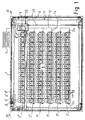
- Fig. 1 and 2 illustrate an automatic dispenser fitted as a dispenser of cigarette packets, which is intended to be placed near a cash desk in a self-service store or supermarket and in which a customer can select a desired packet of cigarettes of a given brand from among a large variety of different kinds and brands of cigarettes.
- the article to be selected in this example is a pack of cigarettes, it is to be understood that the automatic dispenser of the invention can be adapted for other goods as well.
- the automatic dispenser comprises a housing 1, which is a box-like casing inside which the mechanisms of the automatic dispenser are assembled.
- the housing 1 comprises a vertical front wall 2 provided with a delivery orifice 3.
- the delivery orifice 3 is preferably placed in the upper part of the front wall 2.
- the delivery orifice 3 is preferably placed at a height such that it lies somewhat above the cash desk belt so that the pack of cigarettes can be dropped directly from the delivery orifice 3 onto the cash desk belt.
- a stock of goods 4 is provided inside the housing and it contains several sorts of goods, in this example many different brands of cigarettes in cigarette packets.
- a selector device 5 by means of which the user can select the desired item from among the various sorts of goods in stock, is placed within the user's reach.
- the selector device 5 may be e.g. a keyset panel in which each selecting key may be provided with pictures of different packets of cigarettes in the conventional manner.
- the stock of goods 4 is organized in such manner that the automatic dispenser comprises a number of horizontal shelves 7 1 ...7 6 placed one above the other, the example embodiment in Fig. 1 having six shelves. There is no limitation regarding the number of shelves placed above each other; instead, any suitable number of shelves may be used.
- Each shelf 7 1 ...7 6 is provided with compartments 8 1 ...8 16 disposed adjacently to and separated from each other, in which the packets of cigarettes can be placed in horizontal files 9 1 ...9 16 .
- Each compartment 8 1 ...8 16 comprises a front guard 10 for each file of goods.
- Fig. 1 shows the foremost packet in each file of cigarette packets, placed against the front guard 10. All front guards 10 are located in the same vertical plane.
- each compartment 8 1 ...8 16 is provided with a pusher P, which pushes the file of goods toward the front guard 10 so that the foremost item in the file leans against the front guard 10.
- each shelf comprises sixteen compartments 8 1 ..8 16 , so it is possible to load the automatic dispenser with 96 different sorts of goods.
- the number of compartments is not limited, but the dispenser may contain any suitable number of them.
- the pusher P in each compartment 8 1 ...8 16 comprises a slide element 55, which has been arranged to be movable along a groove 57 provided in the bottom 56 of the compartment. Connected to the slide element 55 is a back guard 58.
- a spring 59 acting between the slide element 55 and the bottom 56 exerts a force pushing the slide element 55 and the back guard 58 toward the front guard 10.
- the spring 59 may be e.g. a helical spring formed from spring steel band, producing a substantially constant spring force.
- One end of the spring is connected to the slide element 55 and the other end to the bottom 56 of the compartment 8 1 ...8 16 .
- the file of cigarette packets is placed between the back guard 58 and the front guard 10, the foremost packet in the file being thus pressed against the front guard 10.
- the automatic dispenser further comprises a conveying means 6 which picks up the selected item from the stock of goods and delivers it via the delivery orifice 3 so that the user can reach it.
- the conveying means 6 comprises a planar transfer mechanism 11 operating in a vertical plane on the front side of the shelves 7 1 ...7 6 , between the front guards 10 and the front wall 2.
- the delivery carriage 13 is connected to the planar transfer mechanism 11.
- the delivery carriage 13 can be moved by the planar transfer mechanism 11 in two dimensions in a vertical plane.
- the planar transfer mechanism 11 is able to move the delivery carriage 13 to a position opposite to the file 9 1 ... 9 16 of cigarette packets corresponding to the selected brand of cigarettes, move the foremost cigarette packet in the file over the front guard 10, receive the cigarette packet into the delivery carriage 13 and move the item to the delivery orifice 3, thus bringing it forth so that the user can reach it.
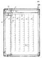
- Fig. 3 outlines the vertical and horizontal paths 14, 15 along which the planar transfer mechanism 11 has been arranged to move the delivery carriage 13.
- the vertical and horizontal transfer paths are because the delivery carriage 13 comprises a cam element 16 extending into the space on the side of the shelves 7 1 ...7 6 relative to the vertical plane formed by the front guards 10.
- the horizontal path 14 of the delivery carriage 13 is in the space between shelves 7 1 ...7 6 , while the vertical path 15 is in the space beside the shelves.
- the paths shown in Fig. 3 represent especially the paths of the cam element 16.
- the front guard 10 at the front end of each shelf 7 1 ...7 6 is provided with a slot 17 extending in the direction of the file of goods 9 1 ...9 16 .
- the delivery carriage 13 comprises a carriage frame 18 fitted in the space between the front guards 10 of the shelves and the front wall 2.
- the cam element 16 extends from the carriage frame 18 to a distance L relative to the front guard that is shorter than the dimension S of the item in the direction of the file.
- Fig. 3 outlines the short transfer paths 60 extending vertically from the horizontal transfer paths 14 between the shelves, representing the passage of the cam element 16 through the slot 17.
- the shelves 7 1 ...7 6 are fitted at a distance from each other such that they form horizontal free spaces between them to provide horizontal paths for the cam element 16.
- the shelves are so fitted inside the housing 1 that a vertical free space is formed in the housing on one side of the shelves to provide a vertical path 15 for the cam element 16.
- the delivery orifice 3 is located in the upper part of the front wall 2 in alignment with the vertical path 15 of the cam element 16.
- the delivery carriage 13 is shown in a position directly opposite to the delivery orifice 3.
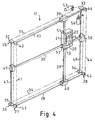
- Fig. 4 - 7 illustrate a preferred construction of the delivery carriage 13.
- the carriage frame 18 comprises a through aperture 19 which is limited in the downward direction by a sloping bottom 20 and in lateral directions by side walls 21, 22.
- the dimensions of the aperture 19 are larger than the outer dimensions of a cigarette packet.
- the front wall 2 of the housing 1 forms a lateral support for the article being conveyed in the aperture 19 of the carriage frame so that the article will only leave the aperture 19 after it has reached the delivery orifice 3.
- the use of the front wall 2 to keep the article in the aperture during the transfer serves the purpose of achieving a delivery carriage 13 that does not have to be provided with any sort of regulating element.
- the housing 1 comprises a door opening 23 disposed on the opposite side of the shelves 7 1 ...7 6 relative to the front wall 2.
- the door opening 23 can be closed with a so-called rulo-door.
- Each shelf 7 1 ...7 6 is supported on the housing 1 by horizontal slide runners 24. Supported by the slide runners 24, the shelves can be extracted through the door opening 23 so that they can be filled from above.
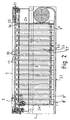
- Fig. 4 illustrates the structure of the planar transfer mechanism 11 used to move the delivery carriage 13.
- the planar transfer mechanism 11 comprises motor-driven belt drive mechanisms 25, 26, 27, 28.
- the vertical and horizontal guide bars 29, 30 are connected to the belt drive mechanisms so that they can be moved in horizontal and vertical directions, said vertical and horizontal guide bars 29, 30 simultaneously acting as guide bars for the delivery carriage 13 to allow the delivery carriage 13 to be moved in a vertical plane.
- a horizontal first belt drive mechanism 25 is disposed in the upper part of the housing 1.
- the first belt drive mechanism 25 comprises an endless first belt 31 and a first pair of belt pulleys 32, 33, over which the first belt is passed.
- a horizontal second belt drive mechanism 26 is disposed in the lower part of the housing 1 at a distance from the first belt drive mechanism.
- the second belt drive mechanism 26 comprises an endless second belt 34 and a second pair of belt pulleys 35, 36, over which the second belt 34 is passed.
- Horizontal first guide bars 37, 38 are placed in the vicinity of the first and second belt drive mechanisms.
- the vertical guide bar 29 is fastened by its ends to the first belt and similarly to the second belt and it extends in a vertical direction in front of the shelves. Connected to the vertical guide bar 29 are first slides 39, 40 near the ends. The first slides 39, 40 are guided by the first guide bars 37, 38.
- a vertical third belt drive mechanism 27 is provided on one side of the housing.
- the third belt drive mechanism 27 comprises an endless third belt 41 and a third pair of belt pulleys 42, 43, over which the third belt is passed.
- a vertical fourth belt drive mechanism 28 is provided on the other side of the housing at a distance from the third belt drive mechanism 27.
- the fourth belt drive mechanism 28 comprises an endless fourth belt 44 and a fourth pair of belt pulleys 45, 46, over which the fourth belt is passed.
- Vertical second guide bars 47, 48 are provided near the third and fourth belt drive mechanisms.
- a horizontal guide bar 30 is fastened by its ends to the third belt 41 and to the fourth belt 44 and extends horizontally in front of the shelves. Connected to the horizontal guide bar 30 are second slides 49, 50 near the ends. The second slides 49, 50 are guided by the second guide bars 47, 48.
- the delivery carriage 13 comprises a vertical first guide sleeve 51, which is guided by the vertical guide bar 29, and a horizontal second guide sleeve 52, which is guided by the horizontal guide bar 30.
- the belt pulleys 32, 33; 35, 36 of the first 25 and the second belt drive mechanism 26 are interconnected by vertical first shafts 47, 48 to synchronize the aforesaid belt drive mechanisms and to transmit traction.
- the first shafts 47, 48 function as aforesaid vertical second guide bars 47, 48 for the second slides 49, 50 placed at the ends of the horizontal guide bar 30 functioning as second guide bars 47, 48.
- the belt pulleys 42, 43; 45, 46 of the third 27 and fourth 28 belt drive mechanisms are interconnected by horizontal second shafts 37, 38 to synchronize the said belt drive mechanisms and to transmit traction.
- the second shafts 37, 38 have been arranged to function as said horizontal first guide bars 37, 38 for the first slides 39, 40 placed at the ends of the vertical guide bar 29.
- the planar transfer mechanism 11 is operated by a first motor 53 driving the first shaft 48 and second motor 54 driving the second shaft 37. No other motors or regulating elements are needed.
- the motors 53, 54 are e.g. servo motors, which can be controlled by a control device and by means of which the position of the delivery carriage 13 can be defined by the control device.
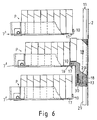
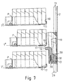
- Fig. 5 - 8 illustrate the delivery process.
- the delivery carriage 13 is in the stand-by position indicated in Fig. 3.
- the planar transfer mechanism 11 moves the delivery carriage 13 along the vertical and horizontal paths 14, 15 to a position below the end of the file corresponding to the selected sort of goods, i.e. in the example in Fig. 5 to a position opposite to the file of goods 9 4 on shelf 7 2 so that the cam element 16 lies directly below the slot 17.
- the delivery carriage 13 is raised so that the first cigarette packet in the file is lifted up and supported by the cam element 16.
- the next cigarette packet in the file, being pushed by the pusher P, is leaning against the forward surface of the cam element 16.
- the delivery carriage 13 is raised until the bottom of the cigarette packet passes over the front guard 10.
- the cam element 16 When the delivery carriage 13 is lowered again, the cam element 16 is disengaged from contact with the next cigarette packet in the file, and this packet is pressed by the pusher P against the front guard 10, thus becoming the foremost packet in the file. At the same time, it pushes the cigarette packet supported by the cam element 16 into the pocket consisting of the through aperture 19 in the delivery carriage 13. Its sloping bottom 20 guides the cigarette packet forward so that it comes to lean against the solid front wall 10 of the housing 1 as shown in Fig. 7.
- the planar transfer mechanism 11 moves the delivery carriage 13 to a position opposite to the delivery orifice 3, with the result that the cigarette packet in the aperture 19 of the delivery carriage 13 falls through the delivery orifice 13 so that it can be picked up by the user.
Landscapes
- Physics & Mathematics (AREA)
- General Physics & Mathematics (AREA)
- Vending Machines For Individual Products (AREA)
Claims (8)
- Distributeur automatique, comprenant- un logement (1) avec une paroi (2) munie d'un orifice de distribution (3) pour distribuer les marchandises ;- un stock de marchandises (4), qui se trouve à l'intérieur du logement et peut contenir différentes sortes de marchandises ;- un dispositif de sélection (5), au moyen duquel l'utilisateur peut sélectionner un article parmi les différentes sortes de marchandises disponibles dans le stock de marchandises ;- un certain nombre d'étagères (71...76) placées les unes au-dessus des autres, chaque étagère comprenant un certain nombre de compartiments adjacents (81...816) dans lesquels les marchandises peuvent être placées en rangées de marchandises (91...916) afin de former ledit stock de marchandises (4), chaque compartiment comprenant un rebord avant (10) pour chaque rangée de marchandises, tous les rebords avant étant situés essentiellement sur le même plan vertical, l'extrémité avant de l'étagère (71...76) et le rebord avant (10) étant munis d'une fente (17) s'étendant dans la direction de la rangée de marchandises (91... 916) ; et- un moyen de transport (6) pour déplacer l'article sélectionné depuis le stock de-marchandises à travers l'orifice de livraison et l'amener à portée de l'utilisateur, ledit moyen de transport (6) comprenantledit chariot de livraison (13) étant relié audit mécanisme de transfert plan (11) qui est disposé afin de déplacer le chariot de livraison (13) le long de passages horizontaux et verticaux (14, 15) vers une position directement opposée à la rangée de marchandises (91... 916) de l'article sélectionné, de déplacer le chariot de livraison (13) verticalement de sorte que la came (16) passe par ladite fente (17) et soulève l'article le plus en avant dans la rangée de marchandises au-dessus du rebord avant (10) de sorte qu'il atteint le chariot de livraison (13), et de déplacer le chariot de livraison (13) vers l'orifice de livraison (3) afin de distribuer l'article, caractérisé en ce que la came (16) est fixée au cadre de chariot (18) et s'étend ainsi de manière fixe depuis le cadre de chariot (18) dans l'espace sur le côté des étagères (71...76) par rapport au plan vertical formé par les rebords avant (10) des étagères et sur une distance (L) inférieure à la dimension (S) de l'article dans la direction de la rangée par rapport au rebord avant (10) ; en ce que les étagères (71...76) sont disposées à une certaine distance les unes des autres afin de former des espaces libres horizontaux entre les étagères afin de fournir des passages horizontaux (14) pour le mouvement de la came (16) ; et en ce que les étagères sont disposées dans l'espace à l'intérieur du logement (1), de sorte qu'au moins un espace libre vertical est formé à l'intérieur du logement afin de fournir un passage vertical (15) pour le mouvement de la came (16).-- un mécanisme de transfert plan (11) agencé afin de fonctionner dans un plan vertical sur le côté avant des étagères (71...76), entre les rebords avant (10) et la paroi (2), et-- un chariot de livraison (13), comprenant un cadre de chariot (18) placé dans l'espace entre les rebords avant (10) et la paroi (2), et une came (16) reliée au cadre de chariot,
- Distributeur automatique tel que défini dans la revendication 1, caractérisé en ce que le distributeur automatique comprend un dispositif de poussée (P) agencé pour pousser la rangée de marchandises (91...916) contre le rebord avant (10) de sorte que l'article le plus en avant de la rangée appuie contre le rebord avant.
- Distributeur automatique tel que défini dans la revendication 1 ou 2, caractérisé en ce que l'orifice de livraison (3) a été placé dans la paroi (2), de préférence dans sa partie supérieure, aligné avec le passage vertical (15) de la came (16).
- Distributeur automatique tel que défini dans l'une quelconque des revendications 1 à 3, caractérisé en ce que le cadre de chariot (18) comprend une ouverture (19) qui est limitée dans la direction vers le bas par un fond en pente (20) et dans les directions latérales par des parois latérales (21, 22) et dont les dimensions sont plus importantes que les dimensions externes de l'article ; et en ce que la paroi (2) forme lors du transport un support latéral pour l'article, qui repose dans l'ouverture (19) du cadre du chariot de sorte qu'il peut uniquement quitter l'ouverture (19) après avoir atteint l'orifice de livraison (3).
- Distributeur automatique tel que défini dans l'une quelconque des revendications 1 à 4, caractérisé en ce que le logement (1) comprend une ouverture de porte (23) disposée sur le côté opposé des étagères (71...76) par rapport à la paroi (2) ; et en ce que chaque étagère est supportée par des glissières horizontales (24) qui permettent de sortir l'étagère par la porte afin de disposer les marchandises sur l'étagère par le dessus.
- Distributeur automatique tel que défini dans l'une quelconque des revendications 1 à 5, caractérisé en ce que le mécanisme de transfert plan (11) comprend des mécanismes d'entraînement par courroie à moteur (25, 26, 27, 28) et des barres de guidage verticales et horizontales (29, 30) reliées aux mécanismes d'entraînement par courroie de sorte qu'elles peuvent être déplacées horizontalement et verticalement, lesdites barres de guidage verticales et horizontales (29, 30) agissant de manière simultanée comme barres de guidage pour le chariot de livraison (13) afin de permettre le déplacement dans un plan vertical du chariot de livraison (13).
- Distributeur automatique tel que défini dans la revendication 6, caractérisé en ce que le mécanisme de transfert (11) comprend- un premier mécanisme d'entraînement par courroie horizontal (25) qui est situé dans la partie supérieure du logement (1) et comprend une première courroie sans fin (31) et une première paire de poulies à courroie (32, 32), ladite première courroie étant passée sur ladite première paire de poulies à courroie,- un deuxième mécanisme d'entraînement par courroie horizontal (26), qui est situé dans la partie inférieure du logement à une certaine distance du premier mécanisme d'entraînement par courroie et comprend une deuxième courroie sans fin (34) et une deuxième paire de poulies à courroie (35, 36), ladite deuxième courroie étant passée sur ladite deuxième paire de poulies à courroie ;- des premières barres de guidage horizontales (37, 38) à proximité des premier et deuxième mécanismes d'entraînement par courroie,- une barre de guidage verticale (29) fixée par ses extrémités à la première courroie et à la deuxième courroie et s'étendant verticalement sur le devant des étagères, avec des premières glissières (39, 40) reliées à ladite barre de guidage verticale à proximité de ses extrémités, lesdites premières glissières étant guidées par lesdites premières barres de guidage (37, 38),- un troisième mécanisme d'entraînement par courroie vertical (27) situé sur un côté du logement de l'appareil et comprenant une troisième courroie sans fin (41) et une troisième paire de poulies à courroie (42, 43), ladite troisième courroie étant passée sur ladite troisième paires de poulies à courroie,- un quatrième mécanisme d'entraînement par courroie vertical (28) situé de l'autre côté du logement à une certaine distance du troisième mécanisme d'entraînement par courroie et comprenant une quatrième courroie sans fin (44) et une quatrième paire de poulies à courroie (45, 46), ladite quatrième courroie étant passée sur ladite quatrième paire de poulies à courroie ;- des secondes barres de guidage verticales (47, 48) à proximité des troisième et quatrième mécanismes d'entraînement par courroie,- une barre de guidage horizontale (30) fixée par ses extrémités à la troisième courroie et à la quatrième courroie et s'étendant horizontalement sur le devant des étagères, avec des secondes glissières (49, 50) reliées à ladite barre de guidage horizontale à proximité de ses extrémités, lesdites secondes glissières étant guidées par lesdites secondes barres de guidage (47, 48),et en ce que le chariot de livraison (13) comprend un premier manchon de guidage vertical (51), qui est guidé par la barre de guidage verticale (29), et un second manchon de guidage horizontal (52), qui est guidé par la barre de guidage horizontale (30).
- Distributeur automatique tel que défini dans la revendication 7, caractérisé en ce que les poulies à courroie (32, 33 ; 35, 36) des premier (25) et deuxième (26) mécanismes d'entraînement par courroie sont reliées par des premiers arbres verticaux (47, 48) afin de synchroniser lesdits mécanismes d'entraînement par courroie et de transmettre la traction ; en ce que le mécanisme de transfert plan (11) comprend un premier moteur (53) afin d'entraîner un premier arbre (47 ou 48) ; et en ce que les premiers arbres (47, 48) sont conçus pour agir en tant que secondes barres de guidage verticales (47, 48) ; et/ou en ce que
les poulies à courroie (42, 43 ; 45, 46) des troisième (27) et quatrième (28) mécanismes d'entraînement par courroie sont reliées par des seconds arbres horizontaux (37, 38) afin de synchroniser lesdits mécanismes d'entraînement par courroie et de transmettre la traction ; en ce que le mécanisme de transfert plan (11) comprend un second moteur (54) afin d'entraîner un second arbre (37 ou 38) ; en ce que les seconds arbres (37, 38) sont conçus pour agir en tant que premières barres de guidage horizontales (37, 38).
Applications Claiming Priority (3)
| Application Number | Priority Date | Filing Date | Title |
|---|---|---|---|
| FI20002371A FI107721B (fi) | 2000-10-27 | 2000-10-27 | Valinta-automaatti |
| FI20002371 | 2000-10-27 | ||
| PCT/FI2001/000912 WO2002035484A1 (fr) | 2000-10-27 | 2001-10-19 | Distributeur automatique |
Publications (2)
| Publication Number | Publication Date |
|---|---|
| EP1337983A1 EP1337983A1 (fr) | 2003-08-27 |
| EP1337983B1 true EP1337983B1 (fr) | 2007-11-21 |
Family
ID=8559384
Family Applications (1)
| Application Number | Title | Priority Date | Filing Date |
|---|---|---|---|
| EP01980560A Expired - Lifetime EP1337983B1 (fr) | 2000-10-27 | 2001-10-19 | Distributeur automatique |
Country Status (5)
| Country | Link |
|---|---|
| EP (1) | EP1337983B1 (fr) |
| AU (1) | AU2002212374A1 (fr) |
| DE (1) | DE60131559D1 (fr) |
| FI (1) | FI107721B (fr) |
| WO (1) | WO2002035484A1 (fr) |
Cited By (3)
| Publication number | Priority date | Publication date | Assignee | Title |
|---|---|---|---|---|
| CN106081460A (zh) * | 2016-08-11 | 2016-11-09 | 苏州欧伟力自动化设备有限公司 | 料盘储放架和料盘储放方法 |
| CN106241168A (zh) * | 2016-09-13 | 2016-12-21 | 国网辽宁省电力有限公司电力科学研究院 | 一种流利货架智能管理装置及方法 |
| WO2024104880A1 (fr) * | 2022-11-14 | 2024-05-23 | Pos Tuning Udo Vosshenrich Gmbh & Co. Kg | Dispositif de séparation de marchandises et procédé de séparation de marchandises, caisse à claires-voies, dispositif de sortie et procédé pour enlever une marchandise d'une caisse à claires-voies |
Families Citing this family (10)
| Publication number | Priority date | Publication date | Assignee | Title |
|---|---|---|---|---|
| EP1911006A4 (fr) * | 2005-07-20 | 2010-10-27 | Coin Acceptors Inc | Procede de modernisation d'un distributeur automatique |
| EP1993078B1 (fr) | 2007-05-16 | 2011-07-27 | Sanden Corporation | Dispositif d'exécution de marchandises |
| EP2012281B1 (fr) * | 2007-05-21 | 2014-11-19 | Sanden Corporation | Dispositif de réalisation de marchandises |
| ES2388097B1 (es) * | 2010-03-22 | 2013-08-23 | Azkoyen, S.A. | Mecanismo contenedor y extractor de productos para máquinas expendedoras. |
| SE1150103A1 (sv) * | 2011-02-10 | 2012-08-11 | Frepart Ab | Lagringssystem |
| US9038852B2 (en) * | 2011-03-16 | 2015-05-26 | Fuji Electric Co., Ltd. | Automatic vending machine |
| EP3861891B1 (fr) * | 2016-12-12 | 2024-01-31 | SMARK GmbH | Système de stockage et de préhension |
| CN108009614A (zh) * | 2018-01-09 | 2018-05-08 | 广州大学 | 一种物品自动分发装置 |
| CN112773106B (zh) * | 2021-02-27 | 2022-07-19 | 东港瑞云数据技术有限公司 | 一种智慧档案存取系统及档案存取方法 |
| DE102024111760A1 (de) * | 2024-04-26 | 2025-10-30 | POS TUNING GmbH | Vorrichtung, Warenausgabeautomat und Verfahren zur Ausgabe von Waren |
Family Cites Families (5)
| Publication number | Priority date | Publication date | Assignee | Title |
|---|---|---|---|---|
| US4134520A (en) * | 1977-01-24 | 1979-01-16 | Rod Pierce & Associates | Article dispensing machine with spring-driven carriages for advancing articles to be dispensed |
| CA1260117A (fr) * | 1985-02-14 | 1989-09-26 | Nelson Vending Technology Limited | Automate vendeur |
| JP3159648B2 (ja) * | 1996-05-17 | 2001-04-23 | 松下冷機株式会社 | 自動販売機の商品搬送装置 |
| JP2000076535A (ja) * | 1998-08-27 | 2000-03-14 | Toshiba Corp | 自動販売機 |
| ID30520A (id) * | 1999-04-02 | 2001-12-13 | Coca Cola Co | Piranti penyaluran dan metode menggunakannya |
-
2000
- 2000-10-27 FI FI20002371A patent/FI107721B/fi active
-
2001
- 2001-10-19 AU AU2002212374A patent/AU2002212374A1/en not_active Abandoned
- 2001-10-19 DE DE60131559T patent/DE60131559D1/de not_active Expired - Lifetime
- 2001-10-19 EP EP01980560A patent/EP1337983B1/fr not_active Expired - Lifetime
- 2001-10-19 WO PCT/FI2001/000912 patent/WO2002035484A1/fr not_active Ceased
Cited By (5)
| Publication number | Priority date | Publication date | Assignee | Title |
|---|---|---|---|---|
| CN106081460A (zh) * | 2016-08-11 | 2016-11-09 | 苏州欧伟力自动化设备有限公司 | 料盘储放架和料盘储放方法 |
| CN106081460B (zh) * | 2016-08-11 | 2018-07-10 | 苏州欧伟力自动化设备有限公司 | 料盘储放方法 |
| CN106241168A (zh) * | 2016-09-13 | 2016-12-21 | 国网辽宁省电力有限公司电力科学研究院 | 一种流利货架智能管理装置及方法 |
| CN106241168B (zh) * | 2016-09-13 | 2019-03-29 | 国网辽宁省电力有限公司电力科学研究院 | 一种流利货架智能管理装置及方法 |
| WO2024104880A1 (fr) * | 2022-11-14 | 2024-05-23 | Pos Tuning Udo Vosshenrich Gmbh & Co. Kg | Dispositif de séparation de marchandises et procédé de séparation de marchandises, caisse à claires-voies, dispositif de sortie et procédé pour enlever une marchandise d'une caisse à claires-voies |
Also Published As
| Publication number | Publication date |
|---|---|
| FI107721B (fi) | 2001-09-28 |
| AU2002212374A1 (en) | 2002-05-06 |
| EP1337983A1 (fr) | 2003-08-27 |
| WO2002035484A1 (fr) | 2002-05-02 |
| DE60131559D1 (de) | 2008-01-03 |
| FI20002371A0 (fi) | 2000-10-27 |
Similar Documents
| Publication | Publication Date | Title |
|---|---|---|
| EP1166241B1 (fr) | Distributeur automatique a face avant transparente | |
| EP1337983B1 (fr) | Distributeur automatique | |
| US6962267B2 (en) | Automated shopping system | |
| US6286715B1 (en) | Transparent front vending machine | |
| US3348732A (en) | Article dispensing device | |
| US6416270B1 (en) | Automated library kiosk | |
| KR100264373B1 (ko) | 패키지 상품의 자동판매기 | |
| US3991907A (en) | Solid merchandise dispensing system for mechanical or electrical control | |
| US6729499B2 (en) | System for conveying a selected product to a collection compartment in automatic vending machines | |
| JP7252848B2 (ja) | 自動販売機、商品収容棚及び商品搬出装置 | |
| JP2957639B2 (ja) | 自動販売機の商品搬送装置 | |
| JP2557504B2 (ja) | 自動販売機 | |
| CN110942554A (zh) | 自动售货设备 | |
| JP2815550B2 (ja) | 搬送装置 | |
| KR0130748B1 (ko) | 자동판매기의 상품수납장치 | |
| JP5272402B2 (ja) | 自動販売機 | |
| JP2009157716A (ja) | 自動販売機 | |
| JP2005128683A (ja) | 自動販売機 | |
| KR19990012026U (ko) | 자동 판매기의 랙크 구동 장치 | |
| JP2005128684A (ja) | 自動販売機 | |
| JPH11175838A (ja) | 自動販売機 | |
| JP2009157718A (ja) | 自動販売機 | |
| JP2906359B2 (ja) | 直積み式自動販売機 | |
| JP2009157717A (ja) | 自動販売機 | |
| JP2007172355A (ja) | 自動販売機の商品搬送装置 |
Legal Events
| Date | Code | Title | Description |
|---|---|---|---|
| PUAI | Public reference made under article 153(3) epc to a published international application that has entered the european phase |
Free format text: ORIGINAL CODE: 0009012 |
|
| 17P | Request for examination filed |
Effective date: 20030509 |
|
| AK | Designated contracting states |
Designated state(s): AT BE CH CY DE DK ES FI FR GB GR IE IT LI LU MC NL PT SE TR |
|
| AX | Request for extension of the european patent |
Extension state: AL LT LV MK RO SI |
|
| 17Q | First examination report despatched |
Effective date: 20061102 |
|
| GRAP | Despatch of communication of intention to grant a patent |
Free format text: ORIGINAL CODE: EPIDOSNIGR1 |
|
| GRAS | Grant fee paid |
Free format text: ORIGINAL CODE: EPIDOSNIGR3 |
|
| GRAA | (expected) grant |
Free format text: ORIGINAL CODE: 0009210 |
|
| AK | Designated contracting states |
Kind code of ref document: B1 Designated state(s): AT BE CH CY DE DK ES FI FR GB GR IE IT LI LU MC NL PT SE TR |
|
| REG | Reference to a national code |
Ref country code: GB Ref legal event code: FG4D |
|
| REG | Reference to a national code |
Ref country code: IE Ref legal event code: FG4D |
|
| REG | Reference to a national code |
Ref country code: CH Ref legal event code: EP |
|
| REF | Corresponds to: |
Ref document number: 60131559 Country of ref document: DE Date of ref document: 20080103 Kind code of ref document: P |
|
| PG25 | Lapsed in a contracting state [announced via postgrant information from national office to epo] |
Ref country code: SE Free format text: LAPSE BECAUSE OF FAILURE TO SUBMIT A TRANSLATION OF THE DESCRIPTION OR TO PAY THE FEE WITHIN THE PRESCRIBED TIME-LIMIT Effective date: 20080221 Ref country code: CH Free format text: LAPSE BECAUSE OF FAILURE TO SUBMIT A TRANSLATION OF THE DESCRIPTION OR TO PAY THE FEE WITHIN THE PRESCRIBED TIME-LIMIT Effective date: 20071121 Ref country code: LI Free format text: LAPSE BECAUSE OF FAILURE TO SUBMIT A TRANSLATION OF THE DESCRIPTION OR TO PAY THE FEE WITHIN THE PRESCRIBED TIME-LIMIT Effective date: 20071121 Ref country code: ES Free format text: LAPSE BECAUSE OF FAILURE TO SUBMIT A TRANSLATION OF THE DESCRIPTION OR TO PAY THE FEE WITHIN THE PRESCRIBED TIME-LIMIT Effective date: 20080304 Ref country code: NL Free format text: LAPSE BECAUSE OF FAILURE TO SUBMIT A TRANSLATION OF THE DESCRIPTION OR TO PAY THE FEE WITHIN THE PRESCRIBED TIME-LIMIT Effective date: 20071121 |
|
| NLV1 | Nl: lapsed or annulled due to failure to fulfill the requirements of art. 29p and 29m of the patents act | ||
| PG25 | Lapsed in a contracting state [announced via postgrant information from national office to epo] |
Ref country code: FI Free format text: LAPSE BECAUSE OF FAILURE TO SUBMIT A TRANSLATION OF THE DESCRIPTION OR TO PAY THE FEE WITHIN THE PRESCRIBED TIME-LIMIT Effective date: 20071121 |
|
| REG | Reference to a national code |
Ref country code: CH Ref legal event code: PL |
|
| PG25 | Lapsed in a contracting state [announced via postgrant information from national office to epo] |
Ref country code: AT Free format text: LAPSE BECAUSE OF FAILURE TO SUBMIT A TRANSLATION OF THE DESCRIPTION OR TO PAY THE FEE WITHIN THE PRESCRIBED TIME-LIMIT Effective date: 20071121 |
|
| PG25 | Lapsed in a contracting state [announced via postgrant information from national office to epo] |
Ref country code: DK Free format text: LAPSE BECAUSE OF FAILURE TO SUBMIT A TRANSLATION OF THE DESCRIPTION OR TO PAY THE FEE WITHIN THE PRESCRIBED TIME-LIMIT Effective date: 20071121 |
|
| PG25 | Lapsed in a contracting state [announced via postgrant information from national office to epo] |
Ref country code: BE Free format text: LAPSE BECAUSE OF FAILURE TO SUBMIT A TRANSLATION OF THE DESCRIPTION OR TO PAY THE FEE WITHIN THE PRESCRIBED TIME-LIMIT Effective date: 20071121 |
|
| PLBE | No opposition filed within time limit |
Free format text: ORIGINAL CODE: 0009261 |
|
| STAA | Information on the status of an ep patent application or granted ep patent |
Free format text: STATUS: NO OPPOSITION FILED WITHIN TIME LIMIT |
|
| PG25 | Lapsed in a contracting state [announced via postgrant information from national office to epo] |
Ref country code: PT Free format text: LAPSE BECAUSE OF FAILURE TO SUBMIT A TRANSLATION OF THE DESCRIPTION OR TO PAY THE FEE WITHIN THE PRESCRIBED TIME-LIMIT Effective date: 20080421 |
|
| 26N | No opposition filed |
Effective date: 20080822 |
|
| PG25 | Lapsed in a contracting state [announced via postgrant information from national office to epo] |
Ref country code: DE Free format text: LAPSE BECAUSE OF FAILURE TO SUBMIT A TRANSLATION OF THE DESCRIPTION OR TO PAY THE FEE WITHIN THE PRESCRIBED TIME-LIMIT Effective date: 20080222 Ref country code: FR Free format text: LAPSE BECAUSE OF FAILURE TO SUBMIT A TRANSLATION OF THE DESCRIPTION OR TO PAY THE FEE WITHIN THE PRESCRIBED TIME-LIMIT Effective date: 20080905 |
|
| PG25 | Lapsed in a contracting state [announced via postgrant information from national office to epo] |
Ref country code: GR Free format text: LAPSE BECAUSE OF FAILURE TO SUBMIT A TRANSLATION OF THE DESCRIPTION OR TO PAY THE FEE WITHIN THE PRESCRIBED TIME-LIMIT Effective date: 20080222 |
|
| PG25 | Lapsed in a contracting state [announced via postgrant information from national office to epo] |
Ref country code: MC Free format text: LAPSE BECAUSE OF NON-PAYMENT OF DUE FEES Effective date: 20081031 |
|
| GBPC | Gb: european patent ceased through non-payment of renewal fee |
Effective date: 20081019 |
|
| PG25 | Lapsed in a contracting state [announced via postgrant information from national office to epo] |
Ref country code: CY Free format text: LAPSE BECAUSE OF FAILURE TO SUBMIT A TRANSLATION OF THE DESCRIPTION OR TO PAY THE FEE WITHIN THE PRESCRIBED TIME-LIMIT Effective date: 20071121 |
|
| PG25 | Lapsed in a contracting state [announced via postgrant information from national office to epo] |
Ref country code: IE Free format text: LAPSE BECAUSE OF NON-PAYMENT OF DUE FEES Effective date: 20081020 |
|
| PG25 | Lapsed in a contracting state [announced via postgrant information from national office to epo] |
Ref country code: GB Free format text: LAPSE BECAUSE OF NON-PAYMENT OF DUE FEES Effective date: 20081019 |
|
| PG25 | Lapsed in a contracting state [announced via postgrant information from national office to epo] |
Ref country code: LU Free format text: LAPSE BECAUSE OF NON-PAYMENT OF DUE FEES Effective date: 20081019 |
|
| PG25 | Lapsed in a contracting state [announced via postgrant information from national office to epo] |
Ref country code: TR Free format text: LAPSE BECAUSE OF FAILURE TO SUBMIT A TRANSLATION OF THE DESCRIPTION OR TO PAY THE FEE WITHIN THE PRESCRIBED TIME-LIMIT Effective date: 20071121 |
|
| PG25 | Lapsed in a contracting state [announced via postgrant information from national office to epo] |
Ref country code: IT Free format text: LAPSE BECAUSE OF NON-PAYMENT OF DUE FEES Effective date: 20081031 |