EP1338557A1 - Method and apparatus for removing sulfur compound in gas containing hydrogen sulfide, mercaptan, carbon dioxide and aromatic hydrocarbon - Google Patents
Method and apparatus for removing sulfur compound in gas containing hydrogen sulfide, mercaptan, carbon dioxide and aromatic hydrocarbon Download PDFInfo
- Publication number
- EP1338557A1 EP1338557A1 EP00969836A EP00969836A EP1338557A1 EP 1338557 A1 EP1338557 A1 EP 1338557A1 EP 00969836 A EP00969836 A EP 00969836A EP 00969836 A EP00969836 A EP 00969836A EP 1338557 A1 EP1338557 A1 EP 1338557A1
- Authority
- EP
- European Patent Office
- Prior art keywords
- gas
- hydrogen sulfide
- sulfur compounds
- mercaptans
- catalyst
- Prior art date
- Legal status (The legal status is an assumption and is not a legal conclusion. Google has not performed a legal analysis and makes no representation as to the accuracy of the status listed.)
- Granted
Links
Images


Classifications
-
- C—CHEMISTRY; METALLURGY
- C10—PETROLEUM, GAS OR COKE INDUSTRIES; TECHNICAL GASES CONTAINING CARBON MONOXIDE; FUELS; LUBRICANTS; PEAT
- C10G—CRACKING HYDROCARBON OILS; PRODUCTION OF LIQUID HYDROCARBON MIXTURES, e.g. BY DESTRUCTIVE HYDROGENATION, OLIGOMERISATION, POLYMERISATION; RECOVERY OF HYDROCARBON OILS FROM OIL-SHALE, OIL-SAND, OR GASES; REFINING MIXTURES MAINLY CONSISTING OF HYDROCARBONS; REFORMING OF NAPHTHA; MINERAL WAXES
- C10G45/00—Refining of hydrocarbon oils using hydrogen or hydrogen-generating compounds
-
- C—CHEMISTRY; METALLURGY
- C10—PETROLEUM, GAS OR COKE INDUSTRIES; TECHNICAL GASES CONTAINING CARBON MONOXIDE; FUELS; LUBRICANTS; PEAT
- C10L—FUELS NOT OTHERWISE PROVIDED FOR; NATURAL GAS; SYNTHETIC NATURAL GAS OBTAINED BY PROCESSES NOT COVERED BY SUBCLASSES C10G OR C10K; LIQUIFIED PETROLEUM GAS; USE OF ADDITIVES TO FUELS OR FIRES; FIRE-LIGHTERS
- C10L3/00—Gaseous fuels; Natural gas; Synthetic natural gas obtained by processes not covered by subclass C10G, C10K; Liquefied petroleum gas
- C10L3/06—Natural gas; Synthetic natural gas obtained by processes not covered by C10G, C10K3/02 or C10K3/04
- C10L3/10—Working-up natural gas or synthetic natural gas
- C10L3/101—Removal of contaminants
- C10L3/102—Removal of contaminants of acid contaminants
-
- C—CHEMISTRY; METALLURGY
- C01—INORGANIC CHEMISTRY
- C01B—NON-METALLIC ELEMENTS; COMPOUNDS THEREOF; METALLOIDS OR COMPOUNDS THEREOF NOT COVERED BY SUBCLASS C01C
- C01B17/00—Sulfur; Compounds thereof
- C01B17/02—Preparation of sulfur; Purification
- C01B17/04—Preparation of sulfur; Purification from gaseous sulfur compounds including gaseous sulfides
- C01B17/0404—Preparation of sulfur; Purification from gaseous sulfur compounds including gaseous sulfides by processes comprising a dry catalytic conversion of hydrogen sulfide-containing gases, e.g. the Claus process
- C01B17/0408—Pretreatment of the hydrogen sulfide containing gases
-
- C—CHEMISTRY; METALLURGY
- C10—PETROLEUM, GAS OR COKE INDUSTRIES; TECHNICAL GASES CONTAINING CARBON MONOXIDE; FUELS; LUBRICANTS; PEAT
- C10L—FUELS NOT OTHERWISE PROVIDED FOR; NATURAL GAS; SYNTHETIC NATURAL GAS OBTAINED BY PROCESSES NOT COVERED BY SUBCLASSES C10G OR C10K; LIQUIFIED PETROLEUM GAS; USE OF ADDITIVES TO FUELS OR FIRES; FIRE-LIGHTERS
- C10L3/00—Gaseous fuels; Natural gas; Synthetic natural gas obtained by processes not covered by subclass C10G, C10K; Liquefied petroleum gas
- C10L3/06—Natural gas; Synthetic natural gas obtained by processes not covered by C10G, C10K3/02 or C10K3/04
- C10L3/10—Working-up natural gas or synthetic natural gas
-
- B—PERFORMING OPERATIONS; TRANSPORTING
- B01—PHYSICAL OR CHEMICAL PROCESSES OR APPARATUS IN GENERAL
- B01D—SEPARATION
- B01D2257/00—Components to be removed
- B01D2257/30—Sulfur compounds
- B01D2257/304—Hydrogen sulfide
-
- B—PERFORMING OPERATIONS; TRANSPORTING
- B01—PHYSICAL OR CHEMICAL PROCESSES OR APPARATUS IN GENERAL
- B01D—SEPARATION
- B01D2257/00—Components to be removed
- B01D2257/30—Sulfur compounds
- B01D2257/306—Organic sulfur compounds, e.g. mercaptans
Definitions
- the present invention relates to a method and apparatus for removing sulfur compounds, such as hydrogen sulfide (H 2 S), mercaptans, and organic sulfur compounds, contained in a natural gas, an associated gas, a synthesis gas, a processing plant gas, a coal gasified gas, or a heavy oil gasified gas (hereinafter abbreviated as "natural gas, etc.," in the present invention).
- sulfur compounds such as hydrogen sulfide (H 2 S), mercaptans, and organic sulfur compounds
- Carbon dioxide (CO 2 ), H 2 S, COS, mercaptans, and aromatic hydrocarbons, are examples of impurity gases contained in natural gas, etc., and these impurity contents tend to gradually increase in recent years in association with decreasing of quality of natural gas, etc., obtained from gas wells. Accordingly, it is necessary to purify the natural gas, etc., by removing the impurity gases therefrom in order to produce a product gas.
- H 2 S containing gas including 20 vol.% or more of CO 2
- the rest of the gas is made to contact with an absorbent which selectively absorbs H 2 S, and H 2 S which is regenerated and separated from the absorbent is returned to the Claus plant.
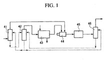
- a residual impurity gas containing CO 2 , H 2 S, mercaptans, and BTX, etc. which is obtained after purifying a product natural gas from a raw natural gas, is separated to a concentrated gas including H 2 S as a main gas and to a residual gas including CO 2 as a main gas, mercaptans, and BTX, in an absorption tower 41 and a regeneration tower 42.
- the concentrated gas is transferred to a Claus sulfur recovering device 43, and a majority of H 2 S is recovered as elementary sulfur in the device 43.
- An off-gas (exhaust gas) from the Claus sulfur recovering device 43 is transferred to a heating furnace 44 together with the above-mentioned residual gas to be heated, and then the heated gas is transferred to a hydrogenation reactor 45.
- sulfur compounds, such as SO 2 , mercaptans, and sulfur vapor, contained in the heated gas is reduced to H 2 S in the presence of a reduction catalyst.
- the obtained H 2 S is separated in an absorption tower 46, and this is returned to the Claus sulfur recovering device 43 via the regeneration tower 42.
- This method of prior application has advantages such as a high removing rate of sulfur from sulfur compounds contained in an impurity gas, prevention of clogging in a catalyst layer of the Claus sulfur recovering device 43, and high quality of recovered elementary.
- soot may be generated due to BTX contained in the residual gas, and the generated soot may flow into the hydrogenation reactor 35 used in the next step so as to deactivate the reduction catalyst or clog the catalyst layer.
- the cause of the problem is found to be direct contact of the residual gas with the flame of a combustion burner of the heating furnace 44, and the temperature at that time is 700°C or higher. Accordingly, the problem may be solved if the residual gas does not make direct contact with the flame, or the gas is not heated to the temperature of 700°C or higher. In order to achieve these, the length of the heating furnace 44 may be increased so that the residual gas is introduced to a low temperature portion separated away from the flame. However, in this manner, a new problem will be created in which the size of the device must be increased.
- mercaptans when a relatively large amount of 1-10 vol.% of mercaptans is contained in the residual gas, mercaptans may be adsorbed by the reduction catalyst in the hydrogenation reactor 45, and this prevents sufficient desulfurization of the mercaptans. Hence, the recovery rate of the sulfur may not be increased in the overall process.
- a first object of the present invention is to prevent the generation of soot in the heating furnace, which is a problem associated with the method for removing sulfur compounds disclosed in Japanese Unexamined Patent Application, First Publication No. Hei 10-28837, and to prevent increase in size of the heating furnace.
- a second object of the present invention is to carry out sufficient desulfurization even when the content of mercaptans in an impurity gas is high, and to improve the recovery rate of sulfur in the overall process.
- a catalyst having a structure in which at least one of cobalt, nickel, and tungsten, in addition to molybdenum are supported by an alumina carrier, in particular, a structure in which molybdenum is concentratedly supported on the surface of catalyst particles, is used.
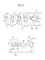
- FIG 2 is a diagram showing an example of an apparatus for carrying out a method of removing sulfur compounds according to the present invention.
- raw natural gas from gas wells is used as a natural gas, etc.
- the raw natural gas is transferred, via a pipe 1, to a first absorption tower 2 where impurity gases accompanying the raw natural gas are non-selectively absorbed, and a purified product natural gas is introduced to a pipe 3 via the top of the tower.
- Aqueous solution of a sulfolane-amine mixed solution, monoethanol amine, diethanol amine, diglycol amine, methanol, or a glycol solution is supplied to the first absorption tower 2 as a non-selective absorption liquid so that a large amount of CO 2 and H 2 S accompanying the raw natural gas, a small amount of sulfur compounds, such as mercaptans, and a small amount of aromatic hydrocarbons, such as BTX, are absorbed.
- the absorption liquid which absorbed the impurity gases is transferred to a first regeneration tower 5 from the bottom of the tower 2 via a pipe 4, and is heated in the first regeneration tower 5 so that the impurity gases are discharged.
- the impurity gases contain, for example, about 70 vol.% of CO 2 , about 25 vol.% of H 2 S, and a small amount of mercaptans, and aromatic hydrocarbons, such as BTX.
- the impurity gases are extracted by a pipe 6 via the top of the tower of the first regeneration tower 5, and the absorption liquid regenerated is returned to the first absorption tower 2 so as to be reutilized, from the bottom of the tower 5 via a pipe 7.
- the impurity gases form the pipe 6 are introduced to a second absorption tower 8.
- a selective absorption liquid comprising an aqueous solution of alkanols, such as diethanol amine, triethanol amine, diisopropanol amine, and methyldiethanol amine, a sulfolane-amine mixed solution, polyethylene glycol dialkylether, or N,N-dimethylamino acetic acid salt is supplied to the second absorption tower 8 where a majority of H 2 S and a part of CO 2 contained in the impurity gas are absorbed.
- these absorption liquids may be used as a non-selective absorption liquid, it may be used as a selective absorption liquid which mainly absorbs H 2 S by selecting absorption conditions.
- the absorption conditions are recognized as a temperature of 60°C or less, preferably between 5 and 40°C, and a pressure of substantially atmospheric pressure or a slightly increased pressure of 2 atmospheres or less.
- a majority of the residual gas consists of CO 2 , and the rest of it includes 0.5-10 vol.% of mercaptans, 0.5-10 vol.% of BTX, and 0.03-0.3 vol.% of H 2 S.
- the absorption liquid drained from the bottom of the second absorption tower 8 is transferred to a second regeneration tower 11 via a pipe 10 where it is heated so that the absorbed H 2 S and CO 2 are discharged.
- the amount of H 2 S becomes 50 vol.% or greater, for instance about 65 vol.% of H 2 S and about 35 vol.% of CO 2 , and a concentrated gas in which H 2 S is concentrated is obtained from the top of the tower.
- the regenerated absorption liquid is returned to the second absorption tower 8 from the bottom of the second regeneration tower 11 via a pipe 12, and is reutilized.
- the second absorption tower 8 and the second regeneration tower 11 constitute a concentration-separation device of the present invention, and it is possible to increase the concentration of H 2 S by providing a plurality of each of these.
- the concentrated gas from the second regeneration tower 11 is transferred, via a pipe 13, to a Claus sulfur recovery unit 14 including a Claus reaction furnace and a multi-layered Claus catalyst layer.
- the Claus sulfur recovery unit 14 has a known structure, and it includes a non-catalyst type and a catalyst type reactor.
- a catalyst alumina, bauxite, titanium, zirconium, silica, zeolite, or these containing oxide of a rare earth metal or an alkaline-earth metal as a thermal stabilizer, is used.
- the reaction temperature is in the range of 1,000 to 1,500°C for the non-catalyst type, and 200 to 350°C for the catalyst type.
- H 2 S in the concentrated gas is oxidized to be SO 2 by the action of an oxygen containing gas, such as oxygen gas and air, which is introduced via a pipe 15, and SO 2 is reacted with the residual H 2 S to form elementary sulfur.
- an oxygen containing gas such as oxygen gas and air
- SO 2 is reacted with the residual H 2 S to form elementary sulfur.
- a majority of H 2 S is converted to elementary sulfur, and recovered from a pipe 16.
- the exhaust gas (off-gas) from the Claus sulfur recovery unit 14 contains traces of H 2 S, SO 2 , S, COS, and CS 2 , a large amount of CO 2 , H 2 , and residual oxygen, and N 2 if air is used as an oxygen source.
- the temperature of the off-gas is normally between 130 and 170°C.
- the off-gas from the Claus sulfur recovery unit 14 is transferred to a heating furnace 18 via a pipe 17.
- FIG. 3 is a diagram showing an example of the heating furnace 18.
- the heating furnace 18 is a transverse type furnace and is provided with a combustion burner 26.
- a fuel gas such as methane and propane, is supplied to the combustion burner 26 via a fuel control valve 27.
- an oxygen-containing gas, such as air is supplied to the heating furnace 18 through a pipe 29 via an air control valve 28.
- the off-gas from the Claus sulfur recovery unit 14 is introduced via a pipe 17. Furthermore, an exhaust pipe 30 is provided from which heated off-gas is emitted, and a first temperature measuring device 31, such as a thermocouple, for measuring the temperature of the exhaust gas is attached to the exhaust pipe 30.
- a first temperature measuring device 31 such as a thermocouple
- a gas mixing device 32 such as a gas mixing device disclosed in Japanese Examined Patent Application, Second Publication No. Sho 58-11247, is connected to the exhaust pipe 30 so that the residual gas from the pipe 9 is mixed with a heated off-gas.
- the mixed gas from the gas mixing device 32 is transferred, via a pipe 33, to a desuifurization reactor 20 used in the next step, and a second temperature measuring device 34, such as a thermocouple, for measuring the temperature of the mixed gas is provided with the pipe 33.
- a second temperature measuring device 34 such as a thermocouple
- a controller 35 which controls the combustion of the heating furnace 18 is provided, and temperature data from the above-mentioned first and second temperature measuring devices 31 and 34 is input into the controller 35. In this manner, the controller 35 controls the fuel control valve 27 and the air control valve 28 so that the temperature of the heated off-gas measured by the first temperature measuring device 31 does not exceed 700°C, and the temperature of the mixed gas measured by the second temperature measuring device 34 is kept within the range of 230-300°C.
- the controller 35 is preset to burn the fuel gas in the heating furnace under a partial oxidation condition in which no oxygen is present in the combustion gas so that CO and H 2 are produced.
- the off-gas introduced into the heating furnace 18 is heated in the above-mentioned manner, and it is transferred together with the combustion gas at a temperature of 700°C or less to the gas mixing device 32 where the gases are mixed with a residual gas. At that time, no soot is generated due to aromatic hydrocarbons, such as BTX, contained in the residual gas.
- the mixed gas is transferred to the desulfurization reactor 20 from the pipe 33 at a temperature of 230-300°C.
- sulfur compounds such as SO 2 , mercaptans, and S contained in the mixed gas are reduced and converted to H 2 S using H 2 contained and H 2 which is produced from a reaction of CO with water.
- Examples of the reduction catalysts used include a catalyst in which at least one of cobalt, nickel, and tungsten, and molybdenum are supported by a carrier comprising ⁇ -alumina or ⁇ -alumina.
- a catalyst including 8-15 wt.% of molybdenum, 2-5 wt.% of cobalt, and the remainder of ⁇ -alumina or ⁇ -alumina, which has an egg-shell structure in which molybdenum is concentratedly supported on the surface of carrier particles, and cobalt is uniformly supported by the entire carrier particles, is preferable.
- the desulfurization process of mercaptans in the desulfurization reactor 20 is carried out by the reaction with accompanying H 2 in accordance with the following reaction scheme (1), (2), and (3): CH 3 SH + H 2 ⁇ CH 4 + H 2 S C 2 H 5 SH + H 2 ⁇ C 2 H 6 + H 2 S C 3 H 7 SH + H 2 ⁇ C 3 H 8 + H 2 S
- reaction may proceed in accordance with the following reaction scheme (4) and (5) in which desulfurization of mercaptans does not require H 2 : C 2 H 5 SH ⁇ C 2 H 4 + H 2 S C 3 H 7 SH ⁇ C 3 H 6 + H 2 S
- the stoichiometric ratio of CO and H 2 in the mixed gas introduced into the desulfurization reactor 20 is 0.5-5, preferably 0.8-4, and desulfurization of mercaptans may be carried out with a small amount of CO and H 2 .
- desulfurization of mercaptan sufficiently proceeds even when the content of mercaptan becomes high.
- the reaction condition in the desulfurization reactor 20 is said to be a temperature of 230-300°C, a pressure of atmospheric pressure to 2 bars, and a gas hourly space velocity of 500-3,000/hr.
- heating of the off-gas transferred from the Claus sulfur recovery unit 14 may be performed by a means other than the heating furnace, for example, by a heat exchanger which burns a fuel gas and applies heat indirectly through a tube wall so that the temperature of the gas after heating becomes 700°C or less.
- a heat exchanger which burns a fuel gas and applies heat indirectly through a tube wall so that the temperature of the gas after heating becomes 700°C or less.
- H 2 , or H 2 and CO which are required in the next step, using the desulfurization reactor 20.
- Hydrogenated gas from the desulfurization reactor 20 includes a few vol.% of H 2 S, a small amount of aromatic hydrocarbons, such as BTX, a trace of unreacted mercaptans, H 2 , and a large amount of CO 2 and N 2 , and the gas is extracted from the pipe 21 to be transferred to a third absorption tower 22 after being cooled.
- a part of the absorbed liquid, which is regenerated in the second regeneration tower 11, is supplied, via a pipe 23, to the third absorption tower 22 as an absorption liquid.
- the absorption liquid which has absorbed H 2 S and CO 2 is returned to the second regeneration tower 11 via a pipe 25 from the bottom of the third absorption tower 22.
- H 2 S and CO 2 are discharged as the above-mentioned concentrated gas, and this is transferred to the Claus sulfur recovery unit 14.
- the residual gas from the second absorption tower 8 is mixed with an off-gas, which is heated to be 700°C or less, no soot is generated due to aromatic hydrocarbons, such as BTX, contained in the residual gas. Accordingly, there is no danger that soot flows into the desulfurization reactor 20 and clogs or deactivates the catalyst layer.
- the above-mentioned catalyst is used as a reduction catalyst for a desulfurization reaction, mercaptans in the residual gas may be converted to H 2 S at a high conversion rate even when the concentration of mercaptans becomes high. Accordingly, the amount of CO or H 2 required for the conversion may be reduced.
- an aqueous solution used in the second absorption tower 8 and the second regeneration tower 11 may be selected as an absorption liquid used in the third absorption tower 22, it is necessary, if the absorption liquid is different from the absorption liquid used in the second absorption tower 8, to separately provide a third regeneration tower so that it is separated from the concentration and separation process.
- an adsorption tower may be provided instead of the third absorption tower 22, in which adsorbent, such as activated carbon or activated carbon immersed with an aqueous solution of compounds that may be reacted with hydrogen sulfide, alumina, iron oxide, and zinc oxide, is filled so that H 2 S is adsorbed and separated.
- adsorbent such as activated carbon or activated carbon immersed with an aqueous solution of compounds that may be reacted with hydrogen sulfide, alumina, iron oxide, and zinc oxide
- the off-gas from the Claus sulfur recovery unit 14 includes CS 2 and COS, it is possible to make the off-gas contact a hydrolysis catalyst after or at the same time as the desulfurization process so that sulfur compounds are converted to H 2 S. Then, these may be separated in the third absorption tower 22, and be returned to the Claus sulfur recovery unit 14.
- a catalyst in which at least one of cobalt, nickel, and tungsten, and molybdenum are supported by a carrier comprising ⁇ -alumina or ⁇ -alumina in particular, if a catalyst including 8-15 wt.% of molybdenum, 2-5 wt.% of cobalt, and the remainder of ⁇ -alumina, which has an egg-shell structure in which molybdenum is concentratedly supported on the surface of carrier particles, and cobalt is uniformly supported on the entire carrier particles, is used as a desulfurization catalyst, mercaptans in the residual gas (impurity gas) may be converted to H 2 S at a high conversion rate even when the concentration of mercaptans becomes high, and the amount of CO and H 2 required for the conversion may be reduced.
- a gas burner was attached to an end of a quartz tube having an inner diameter of 30 mm and a length of 800 mm so that the nozzle of the burner was inserted into the quartz tube.
- Branch tubes were attached to the quartz tube along the length direction of the tube with 100 mm intervals so that gas may be introduced through each of the branch tubes, and a thermocouple was attached to a base portion of each of the branch tubes so that the temperature of the base portion of each branch tube may be measured.
- the gas burner was turned on, and the temperature of the base portion of each branch tube was measured. Also, a test gas comprising 88 vol.% of CO 2 , 2 vol.% of ethylmercaptan, and 10 vol.% of benzene, which corresponds to a residual gas, was introduced into each of the branch tubes to observe the generation of soot when the gas was heated in the quartz tube.
- the catalyst A is a catalyst in which molybdenum is concentratedly supported on the surface of ⁇ -alumina carrier particles, and cobalt is uniformly supported on the entire ⁇ -alumina carrier particles.
- the catalyst A may be obtained in accordance with a method disclosed in, for example, Japanese Unexamined Patent Application, First Publication No. Hei 4-317742.
- the temperature of the impregnation liquid was maintained at 60°C, and 1,000 grams of ⁇ -alumina having a diameter of 2-4 mm was put into a basket made of stainless steel and immersed in the impregnation liquid for 45 minutes. Then, the basket was taken out of the liquid, dewatered, and centrifuged. After being dried for four hours at 120°C, it was calcinated for five hours in air at 500°C.
- the calcinated product obtained was put in a 500 cc beaker, and a solution in which 15 grams of cobalt nitrate hexahydrate was dissolved in 65 cc of pure water was dropped onto the calcinated product using a burette while shaking the product.
- the catalyst obtained had a spherical shape with a diameter of 2-4 mm, and 11.8 wt.% of MoO 3 , and 3.8 wt.% of CoO were contained in the ⁇ -alumina.
- EMA electron probe micro-analyzer
- Cobalt nitrate hexahydrate (15 g) was dissolved in 120 cc of pure water, and 25 cc of 28% ammonia water was added while stirring to obtain a cobalt ammonium complex salt solution.
- 18 grams of ammonium molybdate tetrahydrate was dissolved in 30 cc of 50°C warm water by adding a small amount of ammonia water, and this was added to the above-mentioned cobalt ammonium complex salt solution to obtain an impregnation liquid.
- ⁇ -alumina 1,000 grams having a diameter of 2-4 mm used in the preparation of catalyst A was put into a basket made of stainless steel and immersed in the above-mentioned impregnation liquid for 30 minutes. Then, the basket was taken out of the liquid, dewatered, and centrifuged. After being dried for four hours at 120°C, it was calcinated for five hours in air at 500°C to obtain a catalyst.
- the obtained catalyst contained 12.1 wt.% of MoO 3 , and 4.0 wt.% of CoO in the ⁇ -alumina. Also, as a result of measurements of a metal components concentration distribution in the radius direction of the catalyst using an EPMA, it was confirmed that molybdenum and cobalt were uniformly supported on the entire catalyst.
- This catalyst was the same catalyst which was used in the method disclosed in Japanese Unexamined Patent Application, First Publication No. Hei 10-28837. This catalyst was used as a catalyst B.
- Source gas 1 Source gas 2
- Source gas 3 CO 2 65.2 52.0 52.0 H 2
- 1.0 0.8 0.8 CO 1.0 0.6 0.6 N 2 15.5 28.0 26.5
- Ethylmercaptan 1.5 0.4 1.5
- Stoichiometric ratio (H 2 conc. + CO conc.) / (mercaptan conc.)
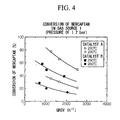
- FIG 4 shows effects of reaction temperature and gas hourly space velocity on the mercaptan conversion when the catalysts A and B are used and the source gas 1 is introduced.
- FIG. 5 shows effects of reaction temperature and gas hourly space velocity on the mercaptan conversion when the catalysts A and B are used and the source gas 2 is introduced.
- the conversion when the catalyst A was used was 79%, and the molar ratio of ethylene to ethane contained in the off-gas was 5.5.
- the conversion when the catalyst B was used was 42%, and the molar ratio of ethylene to ethane contained in the off-gas was 2.1.
- the catalyst A has a better performance than that of the catalyst B even when the stoichiometric ratio is less than one.
- the method and apparatus for removing sulfur compounds according to the present invention may be used for efficiently removing sulfur compounds, such as H 2 S and mercaptans, contained in an impurity gas which is, for example, associated with a natural gas obtained from a natural gas well, and recovering elementary sulfur as a simple substance.
- sulfur compounds such as H 2 S and mercaptans
Landscapes
- Chemical & Material Sciences (AREA)
- Organic Chemistry (AREA)
- Oil, Petroleum & Natural Gas (AREA)
- Chemical Kinetics & Catalysis (AREA)
- Engineering & Computer Science (AREA)
- General Chemical & Material Sciences (AREA)
- Inorganic Chemistry (AREA)
- Catalysts (AREA)
- Treating Waste Gases (AREA)
- Exhaust Gas Treatment By Means Of Catalyst (AREA)
Abstract
Description
| | | Source gas 3 | |
| CO2 | 65.2 | 52.0 | 52.0 |
| H2 | 1.0 | 0.8 | 0.8 |
| CO | 1.0 | 0.6 | 0.6 |
| N2 | 15.5 | 28.0 | 26.5 |
| Toluene | 5.1 | 0.5 | 0.5 |
| H2O | 10.2 | 17.0 | 17.0 |
| Methylmercaptan | 0.3 | 0.05 | 0.3 |
| Ethylmercaptan | 1.5 | 0.4 | 1.5 |
| Propylmercaptan | 0.2 | 0.05 | 0.2 |
| H2S | - | 0.5 | 0.5 |
| SO2 | - | 0.1 | 0.1 |
| stoichiometric ratio | 1.0 | 2.8 | 0.7 |
| Stoichiometric ratio = (H2 conc. + CO conc.) / (mercaptan conc.) |
Claims (8)
- A method for removing sulfur compounds from a gas containing hydrogen sulfide, mercaptans, carbon dioxide and aromatic hydrocarbons, in which sulfur is removed from an impurity gas containing sulfur compounds, such as hydrogen sulfide and mercaptans, carbon dioxide, and aromatic hydrocarbons, the impurity gas being separated from a natural gas, etc., comprising the steps of:transferring the impurity gas to a concentration process in which the impurity gas is separated into a concentrated gas containing hydrogen sulfide as a main substance, and a residual gas containing mercaptans and carbon dioxide as main substances;transferring the concentrated gas to a Claus reaction process in which hydrogen sulfide is recovered as an elementary sulfur, and an off-gas discharged from the Claus reaction process is heated to be a temperature of 700°C or less, the heated off-gas being mixed with the residual gas;transferring a resultant mixed gas to a hydrogenation reaction process in which sulfur compounds, such as mercaptans, are converted into hydrogen sulfide under the presence of a reduction catalyst; andseparating the converted hydrogen sulfide and returning the separated hydrogen sulfide to the Claus reaction process.
- The method for removing sulfur compounds according to claim 1, characterized in that the off-gas is heated in a heating furnace provided with a combustion burner in order to perform a partial oxidation reaction of a fuel so that hydrogen and carbon monoxide are generated.
- The method for removing sulfur compounds according to claim 1, characterized in that the reduction catalyst used in the hydrogenation reaction process is a catalyst in which at least one of cobalt, nickel, and tungsten, and molybdenum are supported by an alumina carrier.
- The method for removing sulfur compounds according to claim 3, characterized in that the reduction catalyst has a structure in which at least one of cobalt, nickel, and tungsten, in addition to molybdenum, are supported by an alumina carrier, and the molybdenum is concentratedly supported on a surface of catalyst particles.
- An apparatus which removes sulfur compounds from a gas containing hydrogen sulfide, mercaptans, carbon dioxide, and aromatic hydrocarbons, in which sulfur is removed from an impurity gas containing sulfur compounds, such as hydrogen sulfide and mercaptans, carbon dioxide, and aromatic hydrocarbons, the impurity gas being separated from a natural gas, etc., comprising:a concentration and separation unit which separates the impurity gas into a concentrated gas containing hydrogen sulfide as a main substance, and a residual gas containing mercaptans and carbon dioxide as main substances;a Claus reaction unit which recovers hydrogen sulfide contained in the concentrated gas transferred from the concentration and separation unit as an elementary sulfur using a Claus reaction;a heating unit which heats an off-gas discharged from the Claus reaction unit to a temperature of 700°C or less;a mixing unit which mixes the heated off-gas from the heating unit with the residual gas;a hydrogenation reactor which includes a reduction catalyst that converts sulfur compounds in the resultant mixed gas from the mixing unit into hydrogen sulfide; anda separation unit which separates hydrogen sulfide in a hydrogenated gas from the hydrogenation reactor and returns the separated hydrogen sulfide to the Claus reaction unit.
- The apparatus for removing sulfur compounds according to claim 5, characterized in that the heating unit is provided with a combustion burner, and a control unit which controls a temperature of the heated off-gas discharged from the heating unit to be 700°C or less, and performs a partial oxidation reaction of a fuel.
- The apparatus for removing sulfur compounds according to claim 5, characterized in that the reduction catalyst used in the hydrogenation reaction unit is a catalyst in which at least one of cobalt, nickel, and tungsten, in addition to molybdenum, are supported by an alumina carrier.
- The apparatus for removing sulfur compounds according to claim 7, characterized in that the reduction catalyst has a structure in which at least one of cobalt, nickel, and tungsten, in addition to molybdenum, are supported by an alumina carrier, and the molybdenum is concentratedly supported on a surface of catalyst particles.
Applications Claiming Priority (1)
| Application Number | Priority Date | Filing Date | Title |
|---|---|---|---|
| PCT/JP2000/007212 WO2002032810A1 (en) | 2000-10-18 | 2000-10-18 | Method and apparatus for removing sulfur compound in gas containing hydrogen sulfide, mercaptan, carbon dioxide and aromatic hydrocarbon |
Publications (3)
| Publication Number | Publication Date |
|---|---|
| EP1338557A1 true EP1338557A1 (en) | 2003-08-27 |
| EP1338557A4 EP1338557A4 (en) | 2004-07-28 |
| EP1338557B1 EP1338557B1 (en) | 2005-03-23 |
Family
ID=11736598
Family Applications (1)
| Application Number | Title | Priority Date | Filing Date |
|---|---|---|---|
| EP00969836A Expired - Lifetime EP1338557B1 (en) | 2000-10-18 | 2000-10-18 | Method and apparatus for removing sulfur compound in gas containing hydrogen sulfide, mercaptan, carbon dioxide and aromatic hydrocarbon |
Country Status (6)
| Country | Link |
|---|---|
| US (1) | US6962680B1 (en) |
| EP (1) | EP1338557B1 (en) |
| JP (1) | JP3847712B2 (en) |
| KR (1) | KR20030045113A (en) |
| DE (1) | DE60018992T2 (en) |
| WO (1) | WO2002032810A1 (en) |
Cited By (29)
| Publication number | Priority date | Publication date | Assignee | Title |
|---|---|---|---|---|
| WO2007065884A1 (en) * | 2005-12-07 | 2007-06-14 | Shell Internationale Research Maatschappij B.V. | Process for the removal of sulphur compounds and carbon dioxide from a gas stream |
| WO2007065765A1 (en) * | 2005-11-04 | 2007-06-14 | Shell Internationale Research Maatschappij B.V. | Process for producing a purified gas stream |
| FR2916652A1 (en) * | 2007-05-30 | 2008-12-05 | Inst Francais Du Petrole | Treating natural gas, comprises contacting natural gas with absorbing solution, introducing solution in column, collecting fraction and treating first and second effluent or contacting natural gas with fraction or dehydrating natural gas |
| CN1754947B (en) * | 2004-09-10 | 2011-05-18 | 道达尔公司 | Process and installation for the treatment of DSO |
| WO2011124326A1 (en) * | 2010-03-29 | 2011-10-13 | Uhde Gmbh | Method and device for processing sour gas rich in carbon dioxide in a claus process |
| CN102502521A (en) * | 2011-11-02 | 2012-06-20 | 陕西科技大学 | Preparation method for sulfur micro-emulsion |
| WO2014006077A1 (en) * | 2012-07-03 | 2014-01-09 | Shell Internationale Research Maatschappij B.V. | Process for deep contaminent removal of gas streams |
| WO2014005817A1 (en) * | 2012-07-06 | 2014-01-09 | Total Sa | Integrated process for native co2 recovery from a sour gas comprising h2s and co2 |
| EP2525892A4 (en) * | 2010-01-22 | 2014-01-22 | Exxonmobil Upstream Res Co | Removal of acid gases from a gas stream, with co2 capture and sequestration |
| RU2509597C1 (en) * | 2012-09-10 | 2014-03-20 | Андрей Владиславович Курочкин | Method of complex preparation of hydrocarbon gas |
| EP2868364A1 (en) | 2013-10-31 | 2015-05-06 | Shell International Research Maatschappij B.V. | Process for producing a purified gas stream |
| WO2016177520A1 (en) * | 2015-05-07 | 2016-11-10 | Axens | Gas treatment method |
| US9752827B2 (en) | 2013-12-06 | 2017-09-05 | Exxonmobil Upstream Research Company | Method and system of maintaining a liquid level in a distillation tower |
| US9803918B2 (en) | 2013-12-06 | 2017-10-31 | Exxonmobil Upstream Research Company | Method and system of dehydrating a feed stream processed in a distillation tower |
| US9823016B2 (en) | 2013-12-06 | 2017-11-21 | Exxonmobil Upstream Research Company | Method and system of modifying a liquid level during start-up operations |
| US9829247B2 (en) | 2013-12-06 | 2017-11-28 | Exxonmobil Upstream Reseach Company | Method and device for separating a feed stream using radiation detectors |
| US9869511B2 (en) | 2013-12-06 | 2018-01-16 | Exxonmobil Upstream Research Company | Method and device for separating hydrocarbons and contaminants with a spray assembly |
| US9874396B2 (en) | 2013-12-06 | 2018-01-23 | Exxonmobil Upstream Research Company | Method and device for separating hydrocarbons and contaminants with a heating mechanism to destabilize and/or prevent adhesion of solids |
| US9874395B2 (en) | 2013-12-06 | 2018-01-23 | Exxonmobil Upstream Research Company | Method and system for preventing accumulation of solids in a distillation tower |
| US9964352B2 (en) | 2012-03-21 | 2018-05-08 | Exxonmobil Upstream Research Company | Separating carbon dioxide and ethane from a mixed stream |
| US10365037B2 (en) | 2015-09-18 | 2019-07-30 | Exxonmobil Upstream Research Company | Heating component to reduce solidification in a cryogenic distillation system |
| US10495379B2 (en) | 2015-02-27 | 2019-12-03 | Exxonmobil Upstream Research Company | Reducing refrigeration and dehydration load for a feed stream entering a cryogenic distillation process |
| EP3750866A1 (en) | 2019-06-12 | 2020-12-16 | Evonik Operations GmbH | Method for manufacturing alcohol made of hydrocarbons |
| US11255603B2 (en) | 2015-09-24 | 2022-02-22 | Exxonmobil Upstream Research Company | Treatment plant for hydrocarbon gas having variable contaminant levels |
| US11306267B2 (en) | 2018-06-29 | 2022-04-19 | Exxonmobil Upstream Research Company | Hybrid tray for introducing a low CO2 feed stream into a distillation tower |
| US11378332B2 (en) | 2018-06-29 | 2022-07-05 | Exxonmobil Upstream Research Company | Mixing and heat integration of melt tray liquids in a cryogenic distillation tower |
| EP4197992A1 (en) | 2021-12-20 | 2023-06-21 | Evonik Operations GmbH | Method for the preparation of an alcohol and separation of the homogeneous catalyst system using a membrane comprising a separation-active layer of paek and a substructure comprising paek |
| EP4477641A1 (en) | 2023-06-14 | 2024-12-18 | Evonik Oxeno GmbH & Co. KG | Method for producing an alcohol by alkoxycarbonylation of di-isobutene using prior distillation and subsequent hydrogenation |
| EP4495091A1 (en) | 2023-07-20 | 2025-01-22 | Evonik Oxeno GmbH & Co. KG | Process for the preparation of alcohols by alkoxycarbonylation of di-isobutene and a c4-c7 olefin followed by hydrogenation |
Families Citing this family (14)
| Publication number | Priority date | Publication date | Assignee | Title |
|---|---|---|---|---|
| US8623308B2 (en) * | 2004-08-02 | 2014-01-07 | Shell Oil Company | Process for removing mercaptans from a gas stream comprising natural gas on an inert gas |
| CN100430315C (en) * | 2006-09-18 | 2008-11-05 | 孔庆然 | Equipment and method for treating exhaust gas for carbon bisulfide preparing process |
| US20080190352A1 (en) | 2007-02-12 | 2008-08-14 | Daewoo Shipbuilding & Marine Engineering Co., Ltd. | Lng tank ship and operation thereof |
| EP2188040A1 (en) * | 2007-08-30 | 2010-05-26 | Shell Internationale Research Maatschappij B.V. | Process for removal of hydrogen sulphide and carbon dioxide from an acid gas stream |
| US20090199591A1 (en) | 2008-02-11 | 2009-08-13 | Daewoo Shipbuilding & Marine Engineering Co., Ltd. | Liquefied natural gas with butane and method of storing and processing the same |
| KR20090107805A (en) | 2008-04-10 | 2009-10-14 | 대우조선해양 주식회사 | Natural gas calorific value reduction method and device |
| MY155414A (en) | 2009-04-20 | 2015-10-15 | Exxonmobil Upstream Res Co | Cryogenic system for removing acid gases from a hydrocarbon gas stream, and method of removing acid gases |
| US8444943B2 (en) | 2010-04-30 | 2013-05-21 | Black & Veatch Corporation | Methods and apparatus for sulfur recovery from acid gases |
| US9562719B2 (en) | 2013-12-06 | 2017-02-07 | Exxonmobil Upstream Research Company | Method of removing solids by modifying a liquid level in a distillation tower |
| US10139158B2 (en) | 2013-12-06 | 2018-11-27 | Exxonmobil Upstream Research Company | Method and system for separating a feed stream with a feed stream distribution mechanism |
| EP3131658B1 (en) * | 2014-04-16 | 2019-09-25 | Saudi Arabian Oil Company | Improved sulfur recovery process for treating low to medium mole percent hydrogen sulfide gas feeds with btex in a claus unit |
| CA3024545C (en) | 2016-03-30 | 2020-08-25 | Exxonmobile Upstream Research Company | Self-sourced reservoir fluid for enhanced oil recovery |
| CN113322105B (en) * | 2021-07-02 | 2024-07-26 | 上海电气集团国控环球工程有限公司 | Efficient debenzolization and purification process of coke oven gas |
| US12285714B2 (en) | 2021-07-13 | 2025-04-29 | Saudi Arabian Oil Company | Robust and sustainable chemical treatment for sulfur contaminants in feed natural gas |
Family Cites Families (14)
| Publication number | Priority date | Publication date | Assignee | Title |
|---|---|---|---|---|
| US3963443A (en) * | 1974-09-23 | 1976-06-15 | Ford, Bacon & Davis Texas Incorporated | Acid gas burner and sulfur recovery system |
| DE2754762C2 (en) | 1977-01-07 | 1987-02-05 | Shell Internationale Research Maatschappij B.V., Den Haag/S'gravenhage | Process for the catalytic combustion of exhaust gas containing hydrogen sulphide and catalyst suitable for carrying out the process |
| DE2851802C2 (en) * | 1978-11-30 | 1985-08-29 | Reitzenstein, Barbara, 8000 München | Device for the extraction of sulfur from gases containing hydrogen sulfide |
| US4382010A (en) * | 1978-12-28 | 1983-05-03 | David Lurie | Desulfurization of flue gases with complete sulfite oxidation |
| JPS57135702A (en) | 1981-02-13 | 1982-08-21 | Res Assoc Residual Oil Process<Rarop> | Fixing of sulfur from exhaust gas of reductive roasting |
| US4430317A (en) * | 1981-03-02 | 1984-02-07 | Standard Oil Company (Indiana) | Low temperature Claus process with water removal |
| JPS5811247A (en) * | 1981-07-14 | 1983-01-22 | 理研軽金属工業株式会社 | Expansion joint |
| US4363790A (en) * | 1981-08-14 | 1982-12-14 | Institute Of Gas Technology | Desulfurization of H2 S containing gas streams with production of elemental sulfur |
| JPS60258294A (en) * | 1984-06-04 | 1985-12-20 | Jgc Corp | Desulfurization refining of natural gas |
| US5176896A (en) * | 1988-06-23 | 1993-01-05 | Texaco Inc. | Apparatus and method for generation of control signal for Claus process optimization |
| JPH04317742A (en) * | 1991-04-15 | 1992-11-09 | Cosmo Sogo Kenkyusho:Kk | Catalytic composition for use in hydrogenation of hydrocarbon oil and its production |
| JPH08290904A (en) * | 1995-04-17 | 1996-11-05 | Mitsubishi Kakoki Kaisha Ltd | Treatment of tail gas in sulfur recovery unit |
| JP3823366B2 (en) | 1996-03-23 | 2006-09-20 | 千代田化工建設株式会社 | Sulfur recovery method and sulfur recovery plant |
| JP3602268B2 (en) * | 1996-07-15 | 2004-12-15 | 日揮株式会社 | Method and apparatus for removing sulfur compounds contained in natural gas and the like |
-
2000
- 2000-10-18 EP EP00969836A patent/EP1338557B1/en not_active Expired - Lifetime
- 2000-10-18 KR KR10-2003-7005280A patent/KR20030045113A/en not_active Ceased
- 2000-10-18 DE DE60018992T patent/DE60018992T2/en not_active Expired - Fee Related
- 2000-10-18 WO PCT/JP2000/007212 patent/WO2002032810A1/en not_active Ceased
- 2000-10-18 US US10/399,382 patent/US6962680B1/en not_active Expired - Fee Related
- 2000-10-18 JP JP2002536001A patent/JP3847712B2/en not_active Expired - Fee Related
Cited By (42)
| Publication number | Priority date | Publication date | Assignee | Title |
|---|---|---|---|---|
| CN1754947B (en) * | 2004-09-10 | 2011-05-18 | 道达尔公司 | Process and installation for the treatment of DSO |
| CN101296861B (en) * | 2005-11-04 | 2012-01-11 | 国际壳牌研究有限公司 | Process for producing a purified gas stream |
| US7625539B2 (en) | 2005-11-04 | 2009-12-01 | Shell Oil Company | Process for producing a purified gas stream |
| EA014412B1 (en) * | 2005-11-04 | 2010-12-30 | Шелл Интернэшнл Рисерч Маатсхаппий Б.В. | Process for producing a purified gas stream |
| WO2007065765A1 (en) * | 2005-11-04 | 2007-06-14 | Shell Internationale Research Maatschappij B.V. | Process for producing a purified gas stream |
| WO2007065884A1 (en) * | 2005-12-07 | 2007-06-14 | Shell Internationale Research Maatschappij B.V. | Process for the removal of sulphur compounds and carbon dioxide from a gas stream |
| AU2006323978B2 (en) * | 2005-12-07 | 2009-10-01 | Shell Internationale Research Maatschappij B.V. | Process for the removal of sulphur compounds and carbon dioxide from a gas stream |
| RU2429899C2 (en) * | 2005-12-07 | 2011-09-27 | Шелл Интернэшнл Рисерч Маатсхаппий Б.В. | Method of removing sulphur compounds and carbon dioxide from gas stream |
| FR2916652A1 (en) * | 2007-05-30 | 2008-12-05 | Inst Francais Du Petrole | Treating natural gas, comprises contacting natural gas with absorbing solution, introducing solution in column, collecting fraction and treating first and second effluent or contacting natural gas with fraction or dehydrating natural gas |
| EP2525892A4 (en) * | 2010-01-22 | 2014-01-22 | Exxonmobil Upstream Res Co | Removal of acid gases from a gas stream, with co2 capture and sequestration |
| WO2011124326A1 (en) * | 2010-03-29 | 2011-10-13 | Uhde Gmbh | Method and device for processing sour gas rich in carbon dioxide in a claus process |
| US8591846B2 (en) | 2010-03-29 | 2013-11-26 | Thyssenkrupp Uhde Gmbh | Method and device for processing sour gas rich in carbon dioxide in a Claus process |
| RU2545273C2 (en) * | 2010-03-29 | 2015-03-27 | ТюссенКрупп Уде ГмбХ | Method and device for processing acid gas enriched with carbon dioxide in claus process |
| CN102502521A (en) * | 2011-11-02 | 2012-06-20 | 陕西科技大学 | Preparation method for sulfur micro-emulsion |
| US9964352B2 (en) | 2012-03-21 | 2018-05-08 | Exxonmobil Upstream Research Company | Separating carbon dioxide and ethane from a mixed stream |
| EA026059B1 (en) * | 2012-07-03 | 2017-02-28 | Шелл Интернэшнл Рисерч Маатсхаппий Б.В. | Process for deep contaminant removal of gas streams |
| WO2014006077A1 (en) * | 2012-07-03 | 2014-01-09 | Shell Internationale Research Maatschappij B.V. | Process for deep contaminent removal of gas streams |
| US9994452B2 (en) | 2012-07-06 | 2018-06-12 | Total Sa | Integrated process for native CO2 recovery from a sour gas comprising H2S and CO2 |
| WO2014005817A1 (en) * | 2012-07-06 | 2014-01-09 | Total Sa | Integrated process for native co2 recovery from a sour gas comprising h2s and co2 |
| EA027424B1 (en) * | 2012-07-06 | 2017-07-31 | Тоталь Са | Integrated process for native corecovery from a sour gas comprising hs and co |
| RU2509597C1 (en) * | 2012-09-10 | 2014-03-20 | Андрей Владиславович Курочкин | Method of complex preparation of hydrocarbon gas |
| EP2868364A1 (en) | 2013-10-31 | 2015-05-06 | Shell International Research Maatschappij B.V. | Process for producing a purified gas stream |
| US9874395B2 (en) | 2013-12-06 | 2018-01-23 | Exxonmobil Upstream Research Company | Method and system for preventing accumulation of solids in a distillation tower |
| US9823016B2 (en) | 2013-12-06 | 2017-11-21 | Exxonmobil Upstream Research Company | Method and system of modifying a liquid level during start-up operations |
| US9829247B2 (en) | 2013-12-06 | 2017-11-28 | Exxonmobil Upstream Reseach Company | Method and device for separating a feed stream using radiation detectors |
| US9869511B2 (en) | 2013-12-06 | 2018-01-16 | Exxonmobil Upstream Research Company | Method and device for separating hydrocarbons and contaminants with a spray assembly |
| US9874396B2 (en) | 2013-12-06 | 2018-01-23 | Exxonmobil Upstream Research Company | Method and device for separating hydrocarbons and contaminants with a heating mechanism to destabilize and/or prevent adhesion of solids |
| US9752827B2 (en) | 2013-12-06 | 2017-09-05 | Exxonmobil Upstream Research Company | Method and system of maintaining a liquid level in a distillation tower |
| US9803918B2 (en) | 2013-12-06 | 2017-10-31 | Exxonmobil Upstream Research Company | Method and system of dehydrating a feed stream processed in a distillation tower |
| US10495379B2 (en) | 2015-02-27 | 2019-12-03 | Exxonmobil Upstream Research Company | Reducing refrigeration and dehydration load for a feed stream entering a cryogenic distillation process |
| US10610853B2 (en) | 2015-05-07 | 2020-04-07 | Axens | Method for treatment of gas |
| FR3035795A1 (en) * | 2015-05-07 | 2016-11-11 | Axens | PROCESS FOR TREATING GAS |
| WO2016177520A1 (en) * | 2015-05-07 | 2016-11-10 | Axens | Gas treatment method |
| US10365037B2 (en) | 2015-09-18 | 2019-07-30 | Exxonmobil Upstream Research Company | Heating component to reduce solidification in a cryogenic distillation system |
| US11255603B2 (en) | 2015-09-24 | 2022-02-22 | Exxonmobil Upstream Research Company | Treatment plant for hydrocarbon gas having variable contaminant levels |
| US11306267B2 (en) | 2018-06-29 | 2022-04-19 | Exxonmobil Upstream Research Company | Hybrid tray for introducing a low CO2 feed stream into a distillation tower |
| US11378332B2 (en) | 2018-06-29 | 2022-07-05 | Exxonmobil Upstream Research Company | Mixing and heat integration of melt tray liquids in a cryogenic distillation tower |
| EP3750866A1 (en) | 2019-06-12 | 2020-12-16 | Evonik Operations GmbH | Method for manufacturing alcohol made of hydrocarbons |
| US11440863B2 (en) | 2019-06-12 | 2022-09-13 | Evonik Operations Gmbh | Process for preparing an alcohol from hydrocarbons |
| EP4197992A1 (en) | 2021-12-20 | 2023-06-21 | Evonik Operations GmbH | Method for the preparation of an alcohol and separation of the homogeneous catalyst system using a membrane comprising a separation-active layer of paek and a substructure comprising paek |
| EP4477641A1 (en) | 2023-06-14 | 2024-12-18 | Evonik Oxeno GmbH & Co. KG | Method for producing an alcohol by alkoxycarbonylation of di-isobutene using prior distillation and subsequent hydrogenation |
| EP4495091A1 (en) | 2023-07-20 | 2025-01-22 | Evonik Oxeno GmbH & Co. KG | Process for the preparation of alcohols by alkoxycarbonylation of di-isobutene and a c4-c7 olefin followed by hydrogenation |
Also Published As
| Publication number | Publication date |
|---|---|
| KR20030045113A (en) | 2003-06-09 |
| EP1338557A4 (en) | 2004-07-28 |
| EP1338557B1 (en) | 2005-03-23 |
| DE60018992T2 (en) | 2006-04-20 |
| US6962680B1 (en) | 2005-11-08 |
| JPWO2002032810A1 (en) | 2004-02-26 |
| JP3847712B2 (en) | 2006-11-22 |
| WO2002032810A1 (en) | 2002-04-25 |
| DE60018992D1 (en) | 2005-04-28 |
Similar Documents
| Publication | Publication Date | Title |
|---|---|---|
| EP1338557B1 (en) | Method and apparatus for removing sulfur compound in gas containing hydrogen sulfide, mercaptan, carbon dioxide and aromatic hydrocarbon | |
| US7138101B2 (en) | Two-stage catalytic process for recovering sulfur from an H2S-containing gas stream | |
| US6962683B2 (en) | Method of removing and recovering elemental sulfur from highly reducing gas streams containing sulfur gases | |
| AU2005206847A1 (en) | Process for the catalytic partial oxidation of H2S using staged addition of oxygen | |
| FI56320C (en) | FOERFARANDE FOER ATT REDUCERA DEN TOTALA SVAVELHALTEN I AVGASER VID EN CLAUSPROCESS | |
| CA3103962C (en) | Catalyst for catalytic oxidative cracking of hydrogen sulphide with concurrent hydrogen production | |
| US8703084B2 (en) | Removal of sulfur compounds from a gas stream | |
| EP0073074B1 (en) | Process for reducing the total sulphur content of a high co2-content feed gas | |
| EP0037158A1 (en) | Process for removing hydrogen cyanide from gaseous streams | |
| JPH02245222A (en) | Desulfuration of gas effluent in circulating fulidized bed by reprodusible absorptive material | |
| JP2002500153A (en) | Improved method for treating H2S lean streams with partial combustion of feed streams | |
| JP3602268B2 (en) | Method and apparatus for removing sulfur compounds contained in natural gas and the like | |
| US7326397B2 (en) | Catalytic partial oxidation process for recovering sulfur from an H2S-containing gas stream | |
| CA2768359C (en) | Removal of sulfur compounds from a gas stream | |
| EP0880395A1 (en) | Method for removing sulfur-containing contaminants, aromatics andhydrocarbons from gas | |
| EA012879B1 (en) | Process for producing a gas stream depleted of hydrogen sulphide | |
| JPH08503651A (en) | Method for removing sulfur dioxide from a sulfur dioxide-containing gas stream | |
| EP0910545A1 (en) | Process for the recovery of sulfur from so 2? containing gases | |
| EP1062025B1 (en) | IMPROVED PROCESS FOR TREATING H2S-LEAN STREAMS WITH RECYCLE OF SOx FROM BURNER | |
| MXPA98005795A (en) | Method for removing contaminants containing sulfur, aromatic compounds and hydrocarbons apparatus of a |
Legal Events
| Date | Code | Title | Description |
|---|---|---|---|
| PUAI | Public reference made under article 153(3) epc to a published international application that has entered the european phase |
Free format text: ORIGINAL CODE: 0009012 |
|
| 17P | Request for examination filed |
Effective date: 20030416 |
|
| AK | Designated contracting states |
Designated state(s): AT BE CH CY DE DK ES FI FR GB GR IE IT LI LU MC NL PT SE |
|
| RIN1 | Information on inventor provided before grant (corrected) |
Inventor name: KIDA, MITSURU,C/O JGC CORPORATION Inventor name: ISHIGAKI, SHINYA,C/O JGC CORP., RESEARCH CENTER Inventor name: SASAKI, TAKASHI,C/O JGC CORPORATION |
|
| RBV | Designated contracting states (corrected) |
Designated state(s): AT BE CH CY DE FR GB IT LI NL |
|
| A4 | Supplementary search report drawn up and despatched |
Effective date: 20040614 |
|
| RIC1 | Information provided on ipc code assigned before grant |
Ipc: 7B 01D 53/34 B Ipc: 7C 01B 17/04 A Ipc: 7C 10L 3/10 B |
|
| GRAP | Despatch of communication of intention to grant a patent |
Free format text: ORIGINAL CODE: EPIDOSNIGR1 |
|
| GRAS | Grant fee paid |
Free format text: ORIGINAL CODE: EPIDOSNIGR3 |
|
| GRAA | (expected) grant |
Free format text: ORIGINAL CODE: 0009210 |
|
| AK | Designated contracting states |
Kind code of ref document: B1 Designated state(s): DE FR GB IT NL |
|
| RBV | Designated contracting states (corrected) |
Designated state(s): DE FR GB IT NL |
|
| REG | Reference to a national code |
Ref country code: GB Ref legal event code: FG4D |
|
| REG | Reference to a national code |
Ref country code: IE Ref legal event code: FG4D |
|
| REF | Corresponds to: |
Ref document number: 60018992 Country of ref document: DE Date of ref document: 20050428 Kind code of ref document: P |
|
| PLBE | No opposition filed within time limit |
Free format text: ORIGINAL CODE: 0009261 |
|
| STAA | Information on the status of an ep patent application or granted ep patent |
Free format text: STATUS: NO OPPOSITION FILED WITHIN TIME LIMIT |
|
| 26N | No opposition filed |
Effective date: 20051227 |
|
| ET | Fr: translation filed | ||
| PGFP | Annual fee paid to national office [announced via postgrant information from national office to epo] |
Ref country code: NL Payment date: 20080829 Year of fee payment: 9 |
|
| PGFP | Annual fee paid to national office [announced via postgrant information from national office to epo] |
Ref country code: GB Payment date: 20080826 Year of fee payment: 9 |
|
| PGFP | Annual fee paid to national office [announced via postgrant information from national office to epo] |
Ref country code: IT Payment date: 20081020 Year of fee payment: 9 |
|
| PGFP | Annual fee paid to national office [announced via postgrant information from national office to epo] |
Ref country code: FR Payment date: 20081029 Year of fee payment: 9 |
|
| PGFP | Annual fee paid to national office [announced via postgrant information from national office to epo] |
Ref country code: DE Payment date: 20090102 Year of fee payment: 9 |
|
| REG | Reference to a national code |
Ref country code: NL Ref legal event code: V1 Effective date: 20100501 |
|
| REG | Reference to a national code |
Ref country code: FR Ref legal event code: ST Effective date: 20100630 |
|
| PG25 | Lapsed in a contracting state [announced via postgrant information from national office to epo] |
Ref country code: NL Free format text: LAPSE BECAUSE OF NON-PAYMENT OF DUE FEES Effective date: 20100501 Ref country code: FR Free format text: LAPSE BECAUSE OF NON-PAYMENT OF DUE FEES Effective date: 20091102 Ref country code: DE Free format text: LAPSE BECAUSE OF NON-PAYMENT OF DUE FEES Effective date: 20100501 |
|
| PG25 | Lapsed in a contracting state [announced via postgrant information from national office to epo] |
Ref country code: GB Free format text: LAPSE BECAUSE OF NON-PAYMENT OF DUE FEES Effective date: 20091018 |
|
| PG25 | Lapsed in a contracting state [announced via postgrant information from national office to epo] |
Ref country code: IT Free format text: LAPSE BECAUSE OF NON-PAYMENT OF DUE FEES Effective date: 20091018 |