EP1338742A1 - Verstellung der Montagehöhe eines über eine Rollvorrichtung verschiebbaren Schiebeflügels - Google Patents
Verstellung der Montagehöhe eines über eine Rollvorrichtung verschiebbaren Schiebeflügels Download PDFInfo
- Publication number
- EP1338742A1 EP1338742A1 EP02004437A EP02004437A EP1338742A1 EP 1338742 A1 EP1338742 A1 EP 1338742A1 EP 02004437 A EP02004437 A EP 02004437A EP 02004437 A EP02004437 A EP 02004437A EP 1338742 A1 EP1338742 A1 EP 1338742A1
- Authority
- EP
- European Patent Office
- Prior art keywords
- arm
- rolling device
- wing
- section
- roller
- Prior art date
- Legal status (The legal status is an assumption and is not a legal conclusion. Google has not performed a legal analysis and makes no representation as to the accuracy of the status listed.)
- Granted
Links
- 230000002787 reinforcement Effects 0.000 claims description 37
- 238000005096 rolling process Methods 0.000 claims description 29
- 230000008859 change Effects 0.000 claims description 20
- 239000002184 metal Substances 0.000 claims description 3
- 229910052751 metal Inorganic materials 0.000 claims description 3
- 235000003332 Ilex aquifolium Nutrition 0.000 claims description 2
- 241000209027 Ilex aquifolium Species 0.000 claims description 2
- 230000005540 biological transmission Effects 0.000 description 4
- 230000009467 reduction Effects 0.000 description 4
- 238000009434 installation Methods 0.000 description 3
- 238000006243 chemical reaction Methods 0.000 description 2
- 238000006073 displacement reaction Methods 0.000 description 2
- NJPPVKZQTLUDBO-UHFFFAOYSA-N novaluron Chemical compound C1=C(Cl)C(OC(F)(F)C(OC(F)(F)F)F)=CC=C1NC(=O)NC(=O)C1=C(F)C=CC=C1F NJPPVKZQTLUDBO-UHFFFAOYSA-N 0.000 description 2
- 238000007789 sealing Methods 0.000 description 2
- 229910000831 Steel Inorganic materials 0.000 description 1
- 230000009471 action Effects 0.000 description 1
- 230000000712 assembly Effects 0.000 description 1
- 238000000429 assembly Methods 0.000 description 1
- 230000008878 coupling Effects 0.000 description 1
- 238000010168 coupling process Methods 0.000 description 1
- 238000005859 coupling reaction Methods 0.000 description 1
- 230000000694 effects Effects 0.000 description 1
- 238000005516 engineering process Methods 0.000 description 1
- 230000002349 favourable effect Effects 0.000 description 1
- 230000007257 malfunction Effects 0.000 description 1
- 230000006641 stabilisation Effects 0.000 description 1
- 238000011105 stabilization Methods 0.000 description 1
- 239000010959 steel Substances 0.000 description 1
- 239000003351 stiffener Substances 0.000 description 1
Images


Classifications
-
- E—FIXED CONSTRUCTIONS
- E05—LOCKS; KEYS; WINDOW OR DOOR FITTINGS; SAFES
- E05D—HINGES OR SUSPENSION DEVICES FOR DOORS, WINDOWS OR WINGS
- E05D15/00—Suspension arrangements for wings
- E05D15/06—Suspension arrangements for wings for wings sliding horizontally more or less in their own plane
- E05D15/0621—Details, e.g. suspension or supporting guides
- E05D15/066—Details, e.g. suspension or supporting guides for wings supported at the bottom
- E05D15/0665—Details, e.g. suspension or supporting guides for wings supported at the bottom on wheels with fixed axis
- E05D15/0669—Details, e.g. suspension or supporting guides for wings supported at the bottom on wheels with fixed axis with height adjustment
-
- E—FIXED CONSTRUCTIONS
- E05—LOCKS; KEYS; WINDOW OR DOOR FITTINGS; SAFES
- E05Y—INDEXING SCHEME ASSOCIATED WITH SUBCLASSES E05D AND E05F, RELATING TO CONSTRUCTION ELEMENTS, ELECTRIC CONTROL, POWER SUPPLY, POWER SIGNAL OR TRANSMISSION, USER INTERFACES, MOUNTING OR COUPLING, DETAILS, ACCESSORIES, AUXILIARY OPERATIONS NOT OTHERWISE PROVIDED FOR, APPLICATION THEREOF
- E05Y2900/00—Application of doors, windows, wings or fittings thereof
- E05Y2900/10—Application of doors, windows, wings or fittings thereof for buildings or parts thereof
- E05Y2900/13—Type of wing
- E05Y2900/132—Doors
Definitions
- the invention deals with the subject area identified by the title. On Wing that can be moved laterally should be adjusted in its height direction, which with one or more of the independent claims is achieved. To this extent Referred.
- EP-B 845 569 (Ferco) in FIG. 1 there and in the associated description.
- a longitudinal pushing and pulling force on the lower wing spar is converted via an inclined surface in the form of a ramp (there the reference numerals 15, 16 and 17 as well as claim 8 and column 5, paragraph # 22) into a height movement to adjust the height of the lower wing spar and with it the entire wing.
- This also corresponds to the basic design of the transmission of a push / pull movement parallel to the longitudinal spar into an oblique movement, as explained in EP-B 563 015 (Giesse) (cf. FIG.
- EP-A 1 116 843 also implements this conversion of the horizontal movement into a change in height according to FIGS. 5, 6 there and the pin arrangement according to FIG. 9 there.
- Device 6,9,14 "emerges. But also here a longitudinal movement of the carriage arrangement provided for the displacement of the wing is provided relative to the lower wing spar, cf.
- EP-A 195 721 (Krieg et Zivy) finally works without a longitudinal movement, in which a vertically oriented screw arrangement 35, 37, 36 causes a change in the height of the wagon wheel 14 there, cf. Figures 1, 3 and 4 there, but the roller is arranged directly at the corner of the wing.
- the invention is based on the task of a height adjustment for a lateral to provide (laterally) sliding wings that are easily accessible and is smooth.
- the accessibility concerns the possibility, settings and also Easy to make adjustments.
- the smoothness affects the Reduction or reduction of the force to be applied to the named Adjustment movement (change in height ⁇ y).
- the invention proposes a device according to claim 1, which as Roll device has at least one rotatable roller on which a mounted wing is laterally displaceable.
- This wing is so far to explain the rolling device used when it is the place of installation (the lower horizontal spar), for which the rolling device is provided.
- the rolling device according to claim 10 also fulfills the above task.
- the swivel arm is in its vertical direction Angular position adjustable, with which angular position the one arranged on the swivel arm at least one role is changed in its altitude relative to the lower spar.
- the swivel arm is not moved in the longitudinal direction, but goes from an in assembled state fixed on the lower pillar bearing block on which pedestal allows a change in the swivel position Bearing point is provided. No ramp is used on one Longitudinal movement is converted into a lifting movement by plain bearings. It will changed a swivel position with which the change in altitude is achieved.
- the end of the actuating arm is preferably near the end of the lateral lower spar and the fixed to the lower spar bracket to be assembled at a considerable distance from it. Between these both positions, the pivoting but immovable bearing at one end of the actuating arm and the point of application of the vertical actuating device at the other end of the lever, the at least one rotatable roller is provided, on which the wing is moved in the course of its sideways movement, supported on a running rail.
- the rotatable roller is thus rotatably supported in the course of the longitudinal extension of the arm, not at one or the other end of this actuating arm (claim 1).
- the Adjustment device changes the swivel position of the actuating arm to increase the mounting height change and thus discontinue.
- This actuating device can be designed for mounting in a vertical groove of the wing be (claim 4), based on the vertical spar of the wing.
- it is in assembled state easily accessible, for example in the form of a screw device, which is adjusted from above to the pivot position of the actuator arm under a heavy accessible lower bar section to change.
- a preferred form of dimensioning the two arm sections, this side and beyond the pivot bearing of the roller are provided, the setting of the Power conversion (claim 2).
- the two arm sections do not have that Extension zero, but each a specific value, depending on the selected Power transmission, relative to the change in height obtained (claim 2, 7).
- the swivel arm does not practice Longitudinal movement from (claim 5), but only a pivoting movement, although with regard to the reference axis of the roller also a slight change in Receives longitudinal direction, but which is much less than that by the Pivotal movement changes in height as measured, for example Distance of the axis of the roller relative to the lower edge of the spar (claim 5).
- a profiled shape can be chosen to make the actuating arm rigid and at the same time easy to design.
- the profiling can serve the Record roller at least in sections, also so that the upper edge of the The roller does not protrude beyond the upper edge of the swivel arm. Claim 22).
- a (metallic) reinforcement of the wing can thus be achieved no need to break through to pick up the roller a bit.
- a corresponding description of the rolling device as such, without reference to the Wing then refers to the bearing of the roller, which is above the top Long side of the pivotable actuator arm is not or at least not significantly protrudes. A rest position so that this long side is essentially parallel to Bottom edge of the wing or for reinforcement runs without interruption of the wing profile or the reinforcement possible.
- the upper long side is a lower long side of the control arm provided that does not need to be flat, but because of the profiling two side retaining flanks can exist, the lower edges of which are "long sides" are viewed (claim 9).
- This long side can - also in the form of the previous one described downward-facing end edge - beveled so that they are not oriented parallel to the upper long side of the pivotable arm.
- a compensation device is provided with which the Pivotal movement of the arm relative to the fixed orientation of the vertical adjustment device can be allowed (claim 15).
- a game-permitting window is preferably arranged here, in which the Force receiving piece is received and held, but a balancing Can perform pivoting movement relative to a center plane of the swivel arm.
- the vertical adjustment device for example in shape a screw / nut combination
- the change in the swivel position of the Swivel arms are allowed when the force receiving piece (the nut) is in the window (opposite) according to the change in the angular position of the Apparently lever arm can shift or pivot. That happens with unchanged permanent vertical orientation of the adjusting device and perpendicular to it oriented mother piece. Actually, that's why the window pivots around them oriented mother around.
- the compensation device is particularly favorable in connection with a Profile design of the swivel arm.
- the adjustment device has a practically unchanged vertical orientation from their assembly in a vertical groove of a vertical wing spar (claim 11, 12).
- An angle can take on the task, on the wing in its vertical To be able to be oriented and a protruding support surface with his to provide an angular protruding section on which a relatively short Adjustment device, for example, can be held in the form of a screw (Claim 12).
- a relatively short Adjustment device for example, can be held in the form of a screw (Claim 12).
- the in essential vertically oriented adjusting device on the one hand rotatably or held, but on the other hand supported practically immovable in the vertical direction, so that the force of the wing is absorbed and the angle on the vertical spar can be transferred (claim 16).
- This counter support can be cone-shaped (claim 17) for example a head of a height change To keep screwing device (claim 17).
- the force required for height adjustment is determined by a Matching the arm sections, each a section of the total length of the pivotable arm (claim 2, 7).
- a power transmission towards lower forces has a reduction in the possible stroke for the Height adjustment result, so that depending on the maximum stroke required Coordination of the two arm sections can be done.
- the arm section that is between the bearing point of the roller and is preferably shorter the bearing block is not slidably mounted (claim 13).
- the wing spar is at least one, preferably one further external and lower-lying (further inside in the spar) reinforcement having.
- the bearing block can be under the reinforcement of the outside Spars extend or - based on the overall strength of the spar - below the outer Reinforcement (located further out) grips to prefer the inner one Reinforcement of the wing spar to be mounted (claims 19 and 20 or 18).
- the bearing block is in its vertical extension (corresponding to the Height direction y, in which the height adjustment ⁇ y of the wing also runs) greater than the greatest height extension of the swivel arm.
- the swivel arm does not have to reach under the outer reinforcement, but rather remains outside (or in the height direction y below) thereof.
- the impeller can, however engage a recess of an outer metallic rail as reinforcement if it is not particularly small (claim 23).
- the intended one Interruption of the outer armouring can continue to add to the pedestal to allow the assembly, by an enlarged breakthrough the further outside to reach through the reinforcement and on a further inside (lower and further reinforcement lying further back in the spar) (Claim 20).
- Metal parts are used as reinforcement, which as elongated metal pieces, are particularly profiled (claim 21).
- the reinforcements to reinforce the wing used, for example in the form of a U-profile with a downward at least partially open U, with a profile groove engaging in the open U, in which groove the Bearing block can be mounted.
- the profile can also have at least one intermediate strut, which on the inner The underside of the profile groove lies substantially, so that two laterally extending Surface pieces result (claim 22) which are arranged within the hollow profile and at least one of these stiffeners can mount the bearing block improve, so make stiffer and firmer.
- the combination of a sliding sash (with window portion and profile sheets) and a fixed frame illustrated in FIG. 1 is designed in such a way that the sash frame is moved relative to the fixed frame. It can be a sideways shift.
- the arrangement can either be designed as a window or as a door, but can also be transferred to other arrangements in which a height adjustment is desired.
- the height adjustment relates to a change in the wing height F in y-direction, while maintaining its lateral displacement possibility in the x-direction in a plane spanned by the frame B.
- the wing is on a roller arrangement to enable the sliding movement held on its lower spar H one-sided or two-sided, especially in the Corner areas, is arranged.
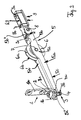
- These roller assemblies have a support arm 5, who carries the said roller.
- the arrangement according to FIG. 2 forms an embodiment of a rolling device, as can be placed at the locations marked in FIG. 1.
- the roller 6 is mounted on a pivot bearing 7 so that it is freely rotatable. It has a running groove 6a, which is delimited by two side webs 6b, to match the design of a running rail, as can be seen in section as a running rail 15 with an arcuate web from FIG. 4.
- An arm which can be pivoted in its pivoting position ⁇ is formed on two sides, with Reference to the axis of rotation 7 of the impeller 6.
- the actuating arm 5 thus has two Sections 5a, 5b, of which one section in FIG. 2 is to the right of the axis of rotation 7 and the other section in Figure 2 is provided to the left of the axis of rotation.
- the right section 5b ends with an end 5b "at a further pivot bearing point 8, which allows a pivoting movement of the arm 5 in the direction ⁇ , but one Longitudinal shift locks.
- the pivot bearing point 8 is coupled to a bearing block 9, whose height extension is h9 and the one bearing section and one Has mounting section.
- the mounting section can be via two openings 9a, 9b the front of the wing, to fix the arm in the x direction.
- the bearing block makes it immovable to mount this spar in one Distance from the corner area of the wing F achieved. From this fixed location the adjusting arm 5 extends in the longitudinal direction (essentially in the direction x) and is can be changed in its pivoting position ⁇ via the bearing point 8. With his It moves due to the fixed mounting of the bearing block not, but only changes its swivel position.
- the rotatable roller is provided in the course of the longitudinal extension of the arm 5 a bearing 7 at a distance from the first pivot bearing 8 and from the (left) End 5a "of the second arm section 5a, of which the bearing 7 also has one Distance.
- the distance of the pivot bearing 7 changes the roller 6 from the lower edge of the lateral wing spar and thus the running height of the Wing F in its lateral adjustment in the x direction.
- several rolling devices several settings are provided by swiveling the (several) arms 5 respectively.
- the installation height can remain fixed, but it can also later be adjusted if it is due to signs of use of the wing appears necessary.
- the adjusting device thus acts on the free end section of the swivel arm 5, that the force used to adjust the leverage law relative to it achieved height adjustment is optimized.
- the first section 5a is preferred between the pivot bearing 7 and the point of attack of the adjusting device larger than the second Section 5b, which is formed between the two bearings 7.8.
- these arm sections have a ratio of about 2: 1, so that force and stroke are divided accordingly.
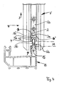
- FIG. 2 The shown embodiment of the vertically acting adjusting device can be illustrated in addition to FIG. 2 also in FIG. 4 in the front view of the outside of the vertical spar.
- An angle 1 with a longer section 1a and a shorter section 1b running essentially perpendicular thereto is provided for mounting in a vertical longitudinal groove of the wing.
- the corresponding assembly openings can be seen in FIGS. 2 and 5; in the assembled state, this corresponds to the location of the position shown in FIG. 4.
- a cone-shaped one Projection 2 provided that a head 3a of a screw device 3 between the short section 1b and tapes.
- the screw device 3, the Has threaded portion 3b and the head portion 3a is y in the vertical direction essentially unchanged, but remains between the pin 2 and the short Angular section 1b rotatably held. This rotation is over the Thread portion 3b in a piece absorbing the vertical force, preferably as one Formed nut piece 4, which is arranged on the swivel arm.
- this nut piece 4 is for a profiled design of the Swivel arm provided so that a window in two web sections of the U-profile 4a is provided that a section of the nut 4, for example a square nut, receives.
- the force-absorbing nut piece is essentially not, at most slightly, shiftable in the direction of rotation, but allows pivoting with respect to the swivel arm 5 or with respect to a central plane of this arm, which runs through the two bearing points 7,8 hypothetically thought.
- the loose receptacle of the nut piece is profiled in the windows described trained swivel arm compensates for the rigid orientation of the vertical Adjustment device from angle 1 and screw device 3 with respect to Rotation of the screw produces a change in the swivel position of the swivel arm 5.
- the nut piece is still capable of vertical Force (corresponding to the weight of the wing F) to absorb and transmit that Adjust swivel position ⁇ of the swivel arm and ease of movement Ensure positioning movement.
- the vertical orientation y in an order - seen from above - is such that a holding function 2, a screwing function 3a and again a holding function 1b are firmly fixed relative to the wing, whereas the adjustment movement thereby exerted on the swivel arm 5 causes a change in the altitude y 1 .
- the distance y 1 is the gap between the lower edge of the sash and the upper edge of the opposite frame section, with two rollovers laterally covering the distance and allowing adjustment such that a change in the height y 1 still does not reveal any gap from the outside ,
- the fitting of the short angle piece 1b with two-sided flanks 1b 'and 1b assures for lateral stabilization within an intended vertical groove.
- the two Projections 1b 'and 1b are matched to the groove dimension.
- This end section 5a" forms the end of the first arm section 5a, while the other end section 5b "forms the opposite end of the forms second arm section 5b, the latter being pivotally arranged on the bearing block 9. Both end sections cannot be displaced in the pushing direction x.
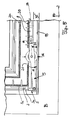
- FIG. 3 forms the zero position with the arm 5 oriented essentially parallel
- FIG. 5 shows the maximum swivel position with the maximum swivel angle ⁇ and the greatest possible spacing y 2 ′ of the two horizontal ones Holme H, B clarifies.
- the action of the adjusting device from the vertical was previously explained and is easily apparent with regard to the functional elements used for this purpose, which have the same reference numerals.
- the previously described lengths A, B for the first and the second Arm sections 5a, 5b are preferably selected in a ratio of 2: 1, whereby this Ratio can change, depending on the necessary height in relation to the actuating force to be used in the y direction on the actuating device 3.1.
- the location of the roller 6 is placed in the zero position with the bearing 7 that a recess 21 in an outer reinforcement 20 at least part of the roller 6 receives. Accordingly, it engages in the interior of the wing spar H. Also in parked state can still part of the roller 6 in this recess 21 according Figure 5 intervene.
- This specific implementation is as follows Versions can be modified.
- the roller 6 can for example be reduced in diameter d6 and in it Bearing 7 are changed to the lower side of the arm so that they only after protrudes below and the arm can maintain its zero position without the upper end the role 6 would extend beyond the reinforcement 20. In such a realization can without an interruption 21 of the outer reinforcement 20 of the wing spar be worked.
- the interruption 21 can also be expanded instead of avoided.
- a Expansion of the interruption in the x direction leads to the bearing block 9 is lowered, the laying of the bearing block 9 at least partially in the wing spar requires that its height h9 be greater. This The height extension is then greater than the height extension h5 of the arm 5, at least in section 5b ", which remains outside the reinforcement.
- bearing block 9 In order to mount the bearing block 9 with an enlarged opening 21, it can do so be dimensioned so that on a second, higher lying in Figure 3 metallic Armor 22 of the horizontal spar is mounted, but under (behind) the outer reinforcement 20 engages. It then has better lateral strength in its assembled position.
- the height adjustment achieved with an associated lowest possible expenditure of force shows the difference between the gap dimensions y 1 and y 2 'in FIGS. 3 and 5.
- the wall section 23 can be the bottom of a standardized profile groove the inner surface of the reinforcement 20 is attached as an "outer reinforcement".
- Reinforcement can - as is also generally known - profiles or steel rails Find use.
- the bearing block 9 can also pass through the wall 23 of the wing profile and close or on (at) the lower one Armor (the inner armor 22) can be arranged as described above.
- the longer first arm section 5a and the shorter arm section 5b have in one Area 5d where they meet, an arcuate course to Reinforcement in the area of bearing 7 of the impeller 6. From the outer end (based on the fixed bearing 8) of the impeller up to this bearing the arm consists of only two wing sections, the bearing 7 and between them pick up the impeller 6.
- This arm section 5d is particularly simple in the profiled version producible and dimensionally stable and easy to assemble.
- the profiled arm is facing down formed open along its entire length, with its lower front edges is bevelled at least in a section of the first arm section 5a, corresponding to an inclination of the front edges 5c with respect to the upper profile ceiling 5a ', that are not parallel to each other.
Landscapes
- Engineering & Computer Science (AREA)
- Mechanical Engineering (AREA)
- Bearings For Parts Moving Linearly (AREA)
- Gates (AREA)
- Power-Operated Mechanisms For Wings (AREA)
- Door And Window Frames Mounted To Openings (AREA)
Abstract
Description
- Figur 1
- ist eine perspektivische Ansicht eines Flügels F mit Vertikal- und Horizontalholm V, H, der innerhalb eines fest stehenden Rahmens als Festrahmen oder Blendrahmen B in Seitenrichtung (lateral) verschiebbar ist. Zur Orientierung sind die näher spezifisch herausgezeichneten Positionen einer Rollenanordnung 5, 6 eingezeichnet, die in den weiteren Figuren vertieft werden. Als Orientierung soll die laterale Schieberichtung mit x und die vertikale Höhenrichtung mit y als Koordinatensystem versehen werden.
- Figur 2
- veranschaulicht eine Rollenvorrichtung, wie sie zuvor skizziert wurde, zur Montage an dem unteren horizontalen Holm H des beschriebenen Flügels in einer perspektivischen Ansicht, aber ohne den zuvor angedeuteten Anbringungsort.
- Figur 3
- veranschaulicht einen vertikalen Schnitt durch den Flügel mit einer Seitenansicht der Rollenvorrichtung nach Figur 2, zur Verdeutlichung der Montage der Anordnung nach Figur 2 an der unteren Stirnfläche des Holms H von Figur 1.
- Figur 4
- veranschaulicht eine Ansicht in Schieberichtung (in Richtung X) der linken vorderen Stirnfläche des vertikalen Holms V von Figur 1, wobei die Rollenvorrichtung 6 in ihrer Nullstellung liegt, bei minimalem y als Höhenverstellung wie auch in Figur 3 gezeigt. Ein Teil des unteren Holms des Blendrahmens B ist im Schnitt dargestellt, zur Verdeutlichung des Orts und der Anbringung der Laufschiene 15, auf der die Rolle 6 läuft. Die Laufrichtung x ist senkrecht zur Papierebene, die Höhenrichtung zur Verstellung ist vertikal orientiert.
- Figur 5
- veranschaulicht dieselbe Ansicht wie Figur 3, nur bei maximaler Höhenverstellung y2' bzw. y2. Der Flügel F hat hierbei seine höchste Position in y-Richtung erreicht, wobei der mögliche Einstellhub der Höhenverstellung zwischen den Darstellungen der Figur 3 und 5 liegt.
Claims (23)
- Vorrichtung zur Montage an einem sich lateral erstreckenden Holm (H) eines zumindest seitlich (lateral) bewegbaren Schiebeflügels (F), um diesen in seiner Montagehöhe (y) einzustellen,
wobei die Rollvorrichtung aufweisteine Einstelleinrichtung (3,4,1) zur Veränderung einer Schwenklage (α) des Stellarms (5), um die Montagehöhe (y;y1,y2) zu verändern und damit einzustellen.(i) einen Lagerbock (9) zur unverschieblichen Montage an dem lateralen Holm in einem Abstand (A+B) von einem Eckbereich des Flügels;(ii) einen sich längs erstreckenden Stellarm (5;5a,5b,5c) mit einem ersten und einem zweiten Endabschnitt (5a",5b"), wobei der zweite Endabschnitt (5b") an dem Lagerbock (9) unverschieblich, aber schwenkbar (8) angeordnet ist;(iii) eine drehbare Rolle (6), welche im Zuge der Längserstreckung des Armes drehbar gelagert ist (7); - Rollvorrichtung nach Anspruch 1, wobei der Stellarm (5) zwei
Armabschnitte (5a,5b) besitzt, einen ersten Armabschnitt (5a) zwischen dem ersten Ende und der drehbaren Rolle (6) und einen zweiten Armabschnitt (5b) zwischen der drehbaren Rolle und dem zweiten Endabschnitt (5b"). - Rollvorrichtung nach Anspruch 1 oder 2, wobei am ersten Endabschnitt (5a") des Stellarms die Einstelleinrichtung (3,3a,3b,4,1) angreift, insbesondere im wesentlichen senkrecht orientiert (y) gegenüber der Orientierung (x) des Stellarms (5).
- Rollvorrichtung nach Anspruch 3, wobei die Einstelleinrichtung (3,4,1) zur Montage in einer vertikalen Nut des Flügels (F) ausgebildet ist (1;1a,1b).
- Rollvorrichtung nach Anspruch 1, wobei nur die Schwenklage (α) des Armes (5), nicht seine Längslage gegenüber dem Lagerbock (9) beim Einstellen der Einstelleinrichtung (3,4,1) verändert wird.
- Rollvorrichtung nach Anspruch 1, wobei die Einstelleinrichtung eine Stellrichtung (y) aufweist, und die Stellrichtung einer Einstellschraube (3) gleichwirkend mit einer Verstellrichtung des Flügels (F) ist.
- Rollvorrichtung nach Anspruch 1, wobei die Rolle (6) in einem Abstand (A,B) von beiden Endabschnitten (5a",5b") des Stellarms angeordnet ist.
- Rollvorrichtung nach Anspruch 1, wobei der Stellarm (5) zumindest abschnittsweise profiliert, insbesondere U-förmig ausgebildet ist.
- Rollvorrichtung nach Anspruch 1 oder 8, wobei der Stellarm im ersten Armabschnitt (5a) eine abgeschrägte Längsseite (5c) aufweist, insbesondere diejenige, die zu einer Laufschiene (15) weist, auf welcher das Laufrad (6) verfahrbar ist.
- Rollvorrichtung zur Montage an einem sich lateral erstreckenden Holm (H) eines Schiebeflügels (F), um diesen in seiner Montagehöhe (y) einzustellen, mit einem schwenkbar gelagerten Arm (5;5a,5b,5c), der im wesentlichen parallel zum unteren Holm sich erstreckend montierbar ist (9), und an dem eine Laufrolle (6) drehbar gelagert ist, wobei eine sich im wesentlichen senkrecht (y) zum Arm (5) erstreckende Stelleinrichtung (1,3,4) vorgesehen ist, um die Schwenklage (α) des Armes (5) zur Veränderung der Montagehöhe des Flügels zu verstellen.
- Rollvorrichtung nach einem der vorigen Ansprüche, wobei die Einstelleinrichtung einen Winkel (1;1a,1b) aufweist, zur Montage in einer vertikalen Nut des Flügels.
- Rollvorrichtung nach einem der vorigen Ansprüche 4 oder 11, wobei der Winkel einen sich im wesentlichen in Richtung des Armes erstreckenden kurzen Abschnitt (1b) und einen längeren Abschnitt (1a) aufweist, und der längere Abschnitt in der vertikalen Nut so montierbar ist, daß der kurze Abschnitt von einem Eckbereich des Flügels weg oder nach außen weist.
- Rollvorrichtung nach einem der vorigen Ansprüche, wobei ein erster
Abschnitt (5a) des Armes auf der einen Längsseite der Rolle (6) länger ist, als ein zweiter Abschnitt (5b) auf der anderen Längsseite der Rolle (6). - Rollvorrichtung nach Anspruch 13, wobei der erste und zweite Abschnitt (5a,5b) des Armes eine jeweilige Länge aufweisen, und das Verhältnis der Längen im wesentlichen 2 : 1 ist.
- Rollvorrichtung nach Anspruch 1 oder 8, wobei der Arm im ersten
Endabschnitt (5a") eine quer zur Längserstreckung des Armes (5) orientierte Ausnehmung (4a), insbesondere in zwei Schenkeln eines U-Profils, aufweist, zur Aufnahme und Halterung eines Kraftaufnahmestücks (4), in welches eine Schraubeinrichtung (3;3b,3a) als Teil der Einstelleinrichtung greift. - Rollvorrichtung nach einem der vorigen Ansprüche, wobei ein Winkel (1) nahe des ersten Endabschnitts (5a") des Armes unverschieblich am Blendrahmen montierbar ist, um eine Schraubeinrichtung (3) drehbar so zu lagern (2), daß eine vertikale Bewegung der Schraubeinrichtung gegenüber dem Winkel im wesentlichen gesperrt wird, aber eine Drehung der Schraubeinrichtung nicht behindert ist.
- Rollvorrichtung nach Anspruch 16, wobei ein Vorsprung, insbesondere als zapfenförmiger Gegenhalt (2) an einem längeren Schenkel (1a) des Winkels so abragend gestaltet ist, daß er einen Kopf (3a) der Schraubeinrichtung zwischen dem Vorsprung und dem kürzeren Schenkel (1b) des Winkels aufnimmt.
- Rollvorrichtung nach einem der vorigen Ansprüche, wobei der Lagerbock (9) so ausgebildet ist, bis unter eine erste Armierung (20) des Holms (H) zu reichen und an einer tiefer liegenden zweiten Armierung (22) montiert zu werden.
- Rollvorrichtung nach einem der vorigen Ansprüche, wobei eine Höhenerstreckung (h9) des Lagerbocks (9) größer ist als eine Höhenerstreckung (h5) des Stellarms (5) zur Montage des Lagerbocks unter einer Armierung (20) des sich lateral erstreckenden Holms (H) des Flügels.
- Rollvorrichtung nach Anspruch 19, wobei die Armierung (20) die äußere von zwei Armierungen (20,22) zur Versteifung eines Kunststoff Flügelprofils als lateralem Holm ist.
- Rollvorrichtung nach Anspruch 1, 18 oder 19, wobei zumindest eine der Armierungen (20,22) ein insbesondere profiliertes Metallstück ist.
- Rollvorrichtung nach Anspruch 18 oder Anspruch 20, wobei beide Armierungen (20,22) des Holms innerhalb eines langgestreckten Hohlraumes eines als Flügelprofils ausgebildeten Holms angeordnet sind.
- Rollvorrichtung nach einem der vorigen Ansprüche, wobei die Laufrolle (6) im Durchmesser so dimensioniert und mit ihrer Drehlagerstelle (7) so am Arm (5) angeordnet ist, daß eine Armierung (20) des Flügels vor der Montage der Rollvorrichtung nicht durchbrochen zu werden braucht, insbesondere eine Lagerstelle (7) der Laufrolle von einer Unterseite der Armierung des Flügels oder einer oberen Längsseite (5a') des schwenkbaren Arms (5) einen größeren Abstand aufweist, als der Radius der Laufrolle.
Priority Applications (1)
| Application Number | Priority Date | Filing Date | Title |
|---|---|---|---|
| EP02004437A EP1338742B1 (de) | 2002-02-22 | 2002-02-26 | Verstellung der Montagehöhe eines über eine Rollvorrichtung verschiebbaren Schiebeflügels |
Applications Claiming Priority (3)
| Application Number | Priority Date | Filing Date | Title |
|---|---|---|---|
| EP02003980 | 2002-02-22 | ||
| EP02003980 | 2002-02-22 | ||
| EP02004437A EP1338742B1 (de) | 2002-02-22 | 2002-02-26 | Verstellung der Montagehöhe eines über eine Rollvorrichtung verschiebbaren Schiebeflügels |
Publications (2)
| Publication Number | Publication Date |
|---|---|
| EP1338742A1 true EP1338742A1 (de) | 2003-08-27 |
| EP1338742B1 EP1338742B1 (de) | 2006-12-27 |
Family
ID=37635978
Family Applications (1)
| Application Number | Title | Priority Date | Filing Date |
|---|---|---|---|
| EP02004437A Expired - Lifetime EP1338742B1 (de) | 2002-02-22 | 2002-02-26 | Verstellung der Montagehöhe eines über eine Rollvorrichtung verschiebbaren Schiebeflügels |
Country Status (4)
| Country | Link |
|---|---|
| EP (1) | EP1338742B1 (de) |
| AT (1) | ATE349592T1 (de) |
| DE (1) | DE50209073D1 (de) |
| ES (1) | ES2278822T3 (de) |
Cited By (4)
| Publication number | Priority date | Publication date | Assignee | Title |
|---|---|---|---|---|
| FR2873743A1 (fr) | 2004-07-27 | 2006-02-03 | M G E Soc Par Actions Simplifi | Procede pour monter et installer un portail et portail pret a la pose |
| CN105735838A (zh) * | 2016-04-08 | 2016-07-06 | 沈阳宝通门业有限公司 | 一种索膜移动折叠大门及其施工方法 |
| CN111877902A (zh) * | 2020-09-18 | 2020-11-03 | 符雪丽 | 无轴承二级调节平移门下滑轮 |
| CN118912092A (zh) * | 2023-06-30 | 2024-11-08 | 华为技术有限公司 | 转轴机构、电子设备 |
Citations (3)
| Publication number | Priority date | Publication date | Assignee | Title |
|---|---|---|---|---|
| US3283444A (en) * | 1964-12-11 | 1966-11-08 | Aluminite Mfg Co | Sliding door corner and roller assembly |
| FR2319040A1 (fr) * | 1975-07-23 | 1977-02-18 | Roc Petits Roulements | Dispositif de reglage et blocage en hauteur d'un galet |
| US5860189A (en) * | 1997-03-06 | 1999-01-19 | An; Tae-Heup | Door wheel |
-
2002
- 2002-02-26 ES ES02004437T patent/ES2278822T3/es not_active Expired - Lifetime
- 2002-02-26 AT AT02004437T patent/ATE349592T1/de not_active IP Right Cessation
- 2002-02-26 EP EP02004437A patent/EP1338742B1/de not_active Expired - Lifetime
- 2002-02-26 DE DE50209073T patent/DE50209073D1/de not_active Expired - Lifetime
Patent Citations (3)
| Publication number | Priority date | Publication date | Assignee | Title |
|---|---|---|---|---|
| US3283444A (en) * | 1964-12-11 | 1966-11-08 | Aluminite Mfg Co | Sliding door corner and roller assembly |
| FR2319040A1 (fr) * | 1975-07-23 | 1977-02-18 | Roc Petits Roulements | Dispositif de reglage et blocage en hauteur d'un galet |
| US5860189A (en) * | 1997-03-06 | 1999-01-19 | An; Tae-Heup | Door wheel |
Cited By (5)
| Publication number | Priority date | Publication date | Assignee | Title |
|---|---|---|---|---|
| FR2873743A1 (fr) | 2004-07-27 | 2006-02-03 | M G E Soc Par Actions Simplifi | Procede pour monter et installer un portail et portail pret a la pose |
| CN105735838A (zh) * | 2016-04-08 | 2016-07-06 | 沈阳宝通门业有限公司 | 一种索膜移动折叠大门及其施工方法 |
| CN105735838B (zh) * | 2016-04-08 | 2017-05-24 | 沈阳宝通门业有限公司 | 一种索膜移动折叠大门及其施工方法 |
| CN111877902A (zh) * | 2020-09-18 | 2020-11-03 | 符雪丽 | 无轴承二级调节平移门下滑轮 |
| CN118912092A (zh) * | 2023-06-30 | 2024-11-08 | 华为技术有限公司 | 转轴机构、电子设备 |
Also Published As
| Publication number | Publication date |
|---|---|
| EP1338742B1 (de) | 2006-12-27 |
| ES2278822T3 (es) | 2007-08-16 |
| ATE349592T1 (de) | 2007-01-15 |
| DE50209073D1 (de) | 2007-02-08 |
Similar Documents
| Publication | Publication Date | Title |
|---|---|---|
| EP0297202B1 (de) | Ausstellvorrichtung für einen Parallelabstell-Schiebeflügel eines Fensters, einer Tür oder dgl. | |
| EP2828460B1 (de) | Beschlag für einen parallel abstellbaren und in dieser parallelabstelllage horizontal verschiebbaren flügel von fenstern oder türen | |
| EP3102759B1 (de) | Beschlag eines zumindest hebbaren und verschiebbaren flügels von fenstern oder türen | |
| EP0586854A2 (de) | Schiebeelement | |
| EP4473180B1 (de) | Verlagerungsvorrichtung zur zwangsweisen verlagerung eines flügels, insbesondere eines schiebeflügels, eines fensters oder einer tür | |
| EP4473179B1 (de) | Verlagerungsvorrichtung zur zwangsweisen verlagerung eines flügels, insbesondere eines schiebeflügels, eines fensters oder einer tür | |
| DE102011085177B4 (de) | Antriebssystem für ein KFZ-Dachsystem | |
| EP3055472B1 (de) | Beschlag eines zumindest hebbaren, vorzugsweise aber auch verschiebbaren flügels von fenstern oder türen | |
| EP1338742B1 (de) | Verstellung der Montagehöhe eines über eine Rollvorrichtung verschiebbaren Schiebeflügels | |
| WO2015067540A1 (de) | Schiebetür oder schiebefenster | |
| EP2696018B1 (de) | Schwenkbare Führungsschere, Lagervorrichtung sowie Führungssystem für Parallel-Ausstellfenster | |
| EP1298271A2 (de) | Laufwagenanordnung für einen Beschlag für Hebe-Schiebe-Türen oder -Fenster sowie Beschlag mit einer solchen Laufwagenanordnung | |
| WO2016023738A1 (de) | Laufwagenanordnung für hebe-schiebe-türen oder -fenster | |
| EP3816383B1 (de) | Schiebetüranordnung | |
| EP1132562A2 (de) | Eckverstärkung oder -versteifung von Schiebeflügeln | |
| DE202014100182U1 (de) | Türbeschlag | |
| EP1605125A2 (de) | Führungssystem zum Führen von Schiebetüren oder Schiebefenstern | |
| DE19851517C1 (de) | Fixiervorrichtung | |
| EP1403459A2 (de) | Trennwand mit horizontal verschiebbaren Schiebeelementen | |
| DE19539014A1 (de) | Schiebetürbeschlag | |
| CH662152A5 (de) | Stellvorrichtung fuer schiebefluegel von fenstern oder tueren. | |
| EP4386163B1 (de) | Schiebetüranordnung | |
| EP0457014A2 (de) | Türverriegelung und mit dieser ausgestatteter Schrankwagen | |
| EP0204057B1 (de) | Vertikalschiebefenster | |
| EP0982456A2 (de) | Einblatt-Überkopftor mit einer über ein Hebelwerk wirkenden Gewichtsausgleichseinrichtung |
Legal Events
| Date | Code | Title | Description |
|---|---|---|---|
| PUAI | Public reference made under article 153(3) epc to a published international application that has entered the european phase |
Free format text: ORIGINAL CODE: 0009012 |
|
| AK | Designated contracting states |
Designated state(s): AT BE CH CY DE DK ES FI FR GB GR IE IT LI LU MC NL PT SE TR |
|
| AX | Request for extension of the european patent |
Extension state: AL LT LV MK RO SI |
|
| 17P | Request for examination filed |
Effective date: 20040123 |
|
| 17Q | First examination report despatched |
Effective date: 20040331 |
|
| AKX | Designation fees paid |
Designated state(s): AT BE CH CY DE DK ES FI FR GB GR IE IT LI LU MC NL PT SE TR |
|
| RAP1 | Party data changed (applicant data changed or rights of an application transferred) |
Owner name: HAUTAU GMBH |
|
| RAP1 | Party data changed (applicant data changed or rights of an application transferred) |
Owner name: HAUTAU GMBH |
|
| GRAP | Despatch of communication of intention to grant a patent |
Free format text: ORIGINAL CODE: EPIDOSNIGR1 |
|
| GRAS | Grant fee paid |
Free format text: ORIGINAL CODE: EPIDOSNIGR3 |
|
| GRAA | (expected) grant |
Free format text: ORIGINAL CODE: 0009210 |
|
| AK | Designated contracting states |
Kind code of ref document: B1 Designated state(s): AT BE CH CY DE DK ES FI FR GB GR IE IT LI LU MC NL PT SE TR |
|
| PG25 | Lapsed in a contracting state [announced via postgrant information from national office to epo] |
Ref country code: IE Free format text: LAPSE BECAUSE OF FAILURE TO SUBMIT A TRANSLATION OF THE DESCRIPTION OR TO PAY THE FEE WITHIN THE PRESCRIBED TIME-LIMIT Effective date: 20061227 Ref country code: NL Free format text: LAPSE BECAUSE OF FAILURE TO SUBMIT A TRANSLATION OF THE DESCRIPTION OR TO PAY THE FEE WITHIN THE PRESCRIBED TIME-LIMIT Effective date: 20061227 Ref country code: DK Free format text: LAPSE BECAUSE OF FAILURE TO SUBMIT A TRANSLATION OF THE DESCRIPTION OR TO PAY THE FEE WITHIN THE PRESCRIBED TIME-LIMIT Effective date: 20061227 Ref country code: FI Free format text: LAPSE BECAUSE OF FAILURE TO SUBMIT A TRANSLATION OF THE DESCRIPTION OR TO PAY THE FEE WITHIN THE PRESCRIBED TIME-LIMIT Effective date: 20061227 |
|
| REG | Reference to a national code |
Ref country code: GB Ref legal event code: FG4D Free format text: NOT ENGLISH |
|
| REG | Reference to a national code |
Ref country code: IE Ref legal event code: FG4D Free format text: LANGUAGE OF EP DOCUMENT: GERMAN |
|
| REF | Corresponds to: |
Ref document number: 50209073 Country of ref document: DE Date of ref document: 20070208 Kind code of ref document: P |
|
| PG25 | Lapsed in a contracting state [announced via postgrant information from national office to epo] |
Ref country code: CH Free format text: LAPSE BECAUSE OF NON-PAYMENT OF DUE FEES Effective date: 20070228 Ref country code: LI Free format text: LAPSE BECAUSE OF NON-PAYMENT OF DUE FEES Effective date: 20070228 Ref country code: MC Free format text: LAPSE BECAUSE OF NON-PAYMENT OF DUE FEES Effective date: 20070228 |
|
| REG | Reference to a national code |
Ref country code: GR Ref legal event code: EP Ref document number: 20070400585 Country of ref document: GR |
|
| PG25 | Lapsed in a contracting state [announced via postgrant information from national office to epo] |
Ref country code: SE Free format text: LAPSE BECAUSE OF FAILURE TO SUBMIT A TRANSLATION OF THE DESCRIPTION OR TO PAY THE FEE WITHIN THE PRESCRIBED TIME-LIMIT Effective date: 20070327 |
|
| GBT | Gb: translation of ep patent filed (gb section 77(6)(a)/1977) |
Effective date: 20070314 |
|
| PG25 | Lapsed in a contracting state [announced via postgrant information from national office to epo] |
Ref country code: PT Free format text: LAPSE BECAUSE OF FAILURE TO SUBMIT A TRANSLATION OF THE DESCRIPTION OR TO PAY THE FEE WITHIN THE PRESCRIBED TIME-LIMIT Effective date: 20070528 |
|
| NLV1 | Nl: lapsed or annulled due to failure to fulfill the requirements of art. 29p and 29m of the patents act | ||
| ET | Fr: translation filed | ||
| REG | Reference to a national code |
Ref country code: ES Ref legal event code: FG2A Ref document number: 2278822 Country of ref document: ES Kind code of ref document: T3 |
|
| REG | Reference to a national code |
Ref country code: CH Ref legal event code: PL |
|
| PLBE | No opposition filed within time limit |
Free format text: ORIGINAL CODE: 0009261 |
|
| STAA | Information on the status of an ep patent application or granted ep patent |
Free format text: STATUS: NO OPPOSITION FILED WITHIN TIME LIMIT |
|
| 26N | No opposition filed |
Effective date: 20070928 |
|
| PG25 | Lapsed in a contracting state [announced via postgrant information from national office to epo] |
Ref country code: AT Free format text: LAPSE BECAUSE OF NON-PAYMENT OF DUE FEES Effective date: 20070226 |
|
| PG25 | Lapsed in a contracting state [announced via postgrant information from national office to epo] |
Ref country code: LU Free format text: LAPSE BECAUSE OF NON-PAYMENT OF DUE FEES Effective date: 20070226 Ref country code: CY Free format text: LAPSE BECAUSE OF FAILURE TO SUBMIT A TRANSLATION OF THE DESCRIPTION OR TO PAY THE FEE WITHIN THE PRESCRIBED TIME-LIMIT Effective date: 20061227 Ref country code: IT Free format text: LAPSE BECAUSE OF NON-PAYMENT OF DUE FEES Effective date: 20080226 |
|
| REG | Reference to a national code |
Ref country code: DE Ref legal event code: R082 Ref document number: 50209073 Country of ref document: DE Representative=s name: PATENT- UND RECHTSANWAELTE LOESENBECK, SPECHT,, DE |
|
| REG | Reference to a national code |
Ref country code: FR Ref legal event code: PLFP Year of fee payment: 14 |
|
| PGFP | Annual fee paid to national office [announced via postgrant information from national office to epo] |
Ref country code: IT Payment date: 20150224 Year of fee payment: 14 Ref country code: ES Payment date: 20150223 Year of fee payment: 14 |
|
| PGFP | Annual fee paid to national office [announced via postgrant information from national office to epo] |
Ref country code: GB Payment date: 20150223 Year of fee payment: 14 Ref country code: TR Payment date: 20150217 Year of fee payment: 14 Ref country code: FR Payment date: 20150217 Year of fee payment: 14 Ref country code: GR Payment date: 20150217 Year of fee payment: 14 |
|
| GBPC | Gb: european patent ceased through non-payment of renewal fee |
Effective date: 20160226 |
|
| REG | Reference to a national code |
Ref country code: FR Ref legal event code: ST Effective date: 20161028 |
|
| PG25 | Lapsed in a contracting state [announced via postgrant information from national office to epo] |
Ref country code: GR Free format text: LAPSE BECAUSE OF NON-PAYMENT OF DUE FEES Effective date: 20160905 |
|
| PG25 | Lapsed in a contracting state [announced via postgrant information from national office to epo] |
Ref country code: IT Free format text: LAPSE BECAUSE OF NON-PAYMENT OF DUE FEES Effective date: 20160226 |
|
| PG25 | Lapsed in a contracting state [announced via postgrant information from national office to epo] |
Ref country code: GB Free format text: LAPSE BECAUSE OF NON-PAYMENT OF DUE FEES Effective date: 20160226 Ref country code: FR Free format text: LAPSE BECAUSE OF NON-PAYMENT OF DUE FEES Effective date: 20160229 |
|
| REG | Reference to a national code |
Ref country code: GR Ref legal event code: ML Ref document number: 20070400585 Country of ref document: GR Effective date: 20160905 |
|
| PGFP | Annual fee paid to national office [announced via postgrant information from national office to epo] |
Ref country code: DE Payment date: 20170224 Year of fee payment: 16 |
|
| PGFP | Annual fee paid to national office [announced via postgrant information from national office to epo] |
Ref country code: BE Payment date: 20170621 Year of fee payment: 16 |
|
| PG25 | Lapsed in a contracting state [announced via postgrant information from national office to epo] |
Ref country code: ES Free format text: LAPSE BECAUSE OF NON-PAYMENT OF DUE FEES Effective date: 20160227 |
|
| REG | Reference to a national code |
Ref country code: DE Ref legal event code: R119 Ref document number: 50209073 Country of ref document: DE |
|
| REG | Reference to a national code |
Ref country code: BE Ref legal event code: MM Effective date: 20180228 |
|
| REG | Reference to a national code |
Ref country code: ES Ref legal event code: FD2A Effective date: 20181205 |
|
| PG25 | Lapsed in a contracting state [announced via postgrant information from national office to epo] |
Ref country code: DE Free format text: LAPSE BECAUSE OF NON-PAYMENT OF DUE FEES Effective date: 20180901 |
|
| PG25 | Lapsed in a contracting state [announced via postgrant information from national office to epo] |
Ref country code: BE Free format text: LAPSE BECAUSE OF NON-PAYMENT OF DUE FEES Effective date: 20180228 |
|
| PG25 | Lapsed in a contracting state [announced via postgrant information from national office to epo] |
Ref country code: TR Free format text: LAPSE BECAUSE OF NON-PAYMENT OF DUE FEES Effective date: 20160226 |