EP1338844A1 - Feu de signalisation comportant une pièce optique réalisant une fonction de signalisation de manière autonome - Google Patents
Feu de signalisation comportant une pièce optique réalisant une fonction de signalisation de manière autonome Download PDFInfo
- Publication number
- EP1338844A1 EP1338844A1 EP03290318A EP03290318A EP1338844A1 EP 1338844 A1 EP1338844 A1 EP 1338844A1 EP 03290318 A EP03290318 A EP 03290318A EP 03290318 A EP03290318 A EP 03290318A EP 1338844 A1 EP1338844 A1 EP 1338844A1
- Authority
- EP
- European Patent Office
- Prior art keywords
- light
- face
- optical axis
- signaling
- optical part
- Prior art date
- Legal status (The legal status is an assumption and is not a legal conclusion. Google has not performed a legal analysis and makes no representation as to the accuracy of the status listed.)
- Granted
Links
- 230000003287 optical effect Effects 0.000 title claims abstract description 141
- 230000009131 signaling function Effects 0.000 title claims description 15
- 238000009826 distribution Methods 0.000 claims abstract description 5
- 230000011664 signaling Effects 0.000 claims description 41
- 230000004907 flux Effects 0.000 claims description 22
- 239000007787 solid Substances 0.000 claims description 4
- 230000007935 neutral effect Effects 0.000 claims description 3
- 238000010137 moulding (plastic) Methods 0.000 claims description 2
- 230000000149 penetrating effect Effects 0.000 claims description 2
- 239000012780 transparent material Substances 0.000 claims description 2
- 230000006870 function Effects 0.000 description 15
- 238000005259 measurement Methods 0.000 description 5
- 229910003460 diamond Inorganic materials 0.000 description 4
- 239000010432 diamond Substances 0.000 description 4
- 235000021183 entrée Nutrition 0.000 description 4
- 239000000463 material Substances 0.000 description 4
- 230000036961 partial effect Effects 0.000 description 4
- 230000002093 peripheral effect Effects 0.000 description 4
- 230000001965 increasing effect Effects 0.000 description 3
- 239000002964 rayon Substances 0.000 description 3
- 239000011521 glass Substances 0.000 description 2
- 238000000465 moulding Methods 0.000 description 2
- 229920003229 poly(methyl methacrylate) Polymers 0.000 description 2
- 239000004926 polymethyl methacrylate Substances 0.000 description 2
- 238000011084 recovery Methods 0.000 description 2
- 230000001105 regulatory effect Effects 0.000 description 2
- 230000009466 transformation Effects 0.000 description 2
- 229920000297 Rayon Polymers 0.000 description 1
- 230000005540 biological transmission Effects 0.000 description 1
- 239000003086 colorant Substances 0.000 description 1
- 238000004040 coloring Methods 0.000 description 1
- 230000000295 complement effect Effects 0.000 description 1
- 238000001816 cooling Methods 0.000 description 1
- 238000002788 crimping Methods 0.000 description 1
- 230000006378 damage Effects 0.000 description 1
- 230000007423 decrease Effects 0.000 description 1
- 238000009792 diffusion process Methods 0.000 description 1
- -1 for example Polymers 0.000 description 1
- 238000002347 injection Methods 0.000 description 1
- 239000007924 injection Substances 0.000 description 1
- 230000000670 limiting effect Effects 0.000 description 1
- 238000004519 manufacturing process Methods 0.000 description 1
- 239000011159 matrix material Substances 0.000 description 1
- 229920003023 plastic Polymers 0.000 description 1
- 230000000750 progressive effect Effects 0.000 description 1
- 230000004224 protection Effects 0.000 description 1
- 230000000717 retained effect Effects 0.000 description 1
- 125000006850 spacer group Chemical group 0.000 description 1
- 238000002604 ultrasonography Methods 0.000 description 1
- 238000003466 welding Methods 0.000 description 1
Images


Classifications
-
- F—MECHANICAL ENGINEERING; LIGHTING; HEATING; WEAPONS; BLASTING
- F21—LIGHTING
- F21V—FUNCTIONAL FEATURES OR DETAILS OF LIGHTING DEVICES OR SYSTEMS THEREOF; STRUCTURAL COMBINATIONS OF LIGHTING DEVICES WITH OTHER ARTICLES, NOT OTHERWISE PROVIDED FOR
- F21V7/00—Reflectors for light sources
- F21V7/0091—Reflectors for light sources using total internal reflection
-
- F—MECHANICAL ENGINEERING; LIGHTING; HEATING; WEAPONS; BLASTING
- F21—LIGHTING
- F21S—NON-PORTABLE LIGHTING DEVICES; SYSTEMS THEREOF; VEHICLE LIGHTING DEVICES SPECIALLY ADAPTED FOR VEHICLE EXTERIORS
- F21S43/00—Signalling devices specially adapted for vehicle exteriors, e.g. brake lamps, direction indicator lights or reversing lights
- F21S43/20—Signalling devices specially adapted for vehicle exteriors, e.g. brake lamps, direction indicator lights or reversing lights characterised by refractors, transparent cover plates, light guides or filters
- F21S43/26—Refractors, transparent cover plates, light guides or filters not provided in groups F21S43/235 - F21S43/255
-
- F—MECHANICAL ENGINEERING; LIGHTING; HEATING; WEAPONS; BLASTING
- F21—LIGHTING
- F21S—NON-PORTABLE LIGHTING DEVICES; SYSTEMS THEREOF; VEHICLE LIGHTING DEVICES SPECIALLY ADAPTED FOR VEHICLE EXTERIORS
- F21S43/00—Signalling devices specially adapted for vehicle exteriors, e.g. brake lamps, direction indicator lights or reversing lights
- F21S43/30—Signalling devices specially adapted for vehicle exteriors, e.g. brake lamps, direction indicator lights or reversing lights characterised by reflectors
- F21S43/31—Optical layout thereof
- F21S43/315—Optical layout thereof using total internal reflection
-
- F—MECHANICAL ENGINEERING; LIGHTING; HEATING; WEAPONS; BLASTING
- F21—LIGHTING
- F21V—FUNCTIONAL FEATURES OR DETAILS OF LIGHTING DEVICES OR SYSTEMS THEREOF; STRUCTURAL COMBINATIONS OF LIGHTING DEVICES WITH OTHER ARTICLES, NOT OTHERWISE PROVIDED FOR
- F21V5/00—Refractors for light sources
- F21V5/04—Refractors for light sources of lens shape
-
- F—MECHANICAL ENGINEERING; LIGHTING; HEATING; WEAPONS; BLASTING
- F21—LIGHTING
- F21S—NON-PORTABLE LIGHTING DEVICES; SYSTEMS THEREOF; VEHICLE LIGHTING DEVICES SPECIALLY ADAPTED FOR VEHICLE EXTERIORS
- F21S41/00—Illuminating devices specially adapted for vehicle exteriors, e.g. headlamps
- F21S41/30—Illuminating devices specially adapted for vehicle exteriors, e.g. headlamps characterised by reflectors
- F21S41/32—Optical layout thereof
- F21S41/322—Optical layout thereof the reflector using total internal reflection
-
- F—MECHANICAL ENGINEERING; LIGHTING; HEATING; WEAPONS; BLASTING
- F21—LIGHTING
- F21S—NON-PORTABLE LIGHTING DEVICES; SYSTEMS THEREOF; VEHICLE LIGHTING DEVICES SPECIALLY ADAPTED FOR VEHICLE EXTERIORS
- F21S43/00—Signalling devices specially adapted for vehicle exteriors, e.g. brake lamps, direction indicator lights or reversing lights
- F21S43/40—Signalling devices specially adapted for vehicle exteriors, e.g. brake lamps, direction indicator lights or reversing lights characterised by the combination of reflectors and refractors
-
- F—MECHANICAL ENGINEERING; LIGHTING; HEATING; WEAPONS; BLASTING
- F21—LIGHTING
- F21Y—INDEXING SCHEME ASSOCIATED WITH SUBCLASSES F21K, F21L, F21S and F21V, RELATING TO THE FORM OR THE KIND OF THE LIGHT SOURCES OR OF THE COLOUR OF THE LIGHT EMITTED
- F21Y2115/00—Light-generating elements of semiconductor light sources
- F21Y2115/10—Light-emitting diodes [LED]
Definitions
- the invention proposes a signaling light in particular for a motor vehicle.
- a traffic light performing a function of fog light must form, on a measurement screen placed ten meters, an image which has the overall shape of a rhombus.
- This diamond is defined by characteristic points which are arranged on the measurement screen and which must receive each a light intensity whose value must be understood within a specified interval.
- a traffic light carrying out a reversing light function must form on the measurement screen a rectangle of determined dimensions and whose length is parallel to the horizontal plane.
- a signaling light of the type described in the document FR-A-2.507.741 generally requires several optical parts to achieve the desired signaling function.
- a first optical part, or recuperator of flux is intended to recover the luminous flux emitted by the source and focus it on the back side of a second piece optic, or flux diffuser, which is placed axially at the front flow recuperator.
- the flow diffuser is designed to spatially distribute the luminous flux towards the front, so as to form a beam bright whose image, on a measurement screen placed at ten meters, is in line with the image of the function to be performed, for example a diamond, for a fog light function according to European regulations, or a stretched rectangle horizontally, for a reversing light function.
- the invention aims in particular to reduce the number of parts necessary to perform a signaling function determined and to reduce the size of the traffic light.
- the invention provides a signaling light of the type described above, characterized in that characterized in that the exit face is formed of a series of elementary dioptric distribution elements, each of which is designed to form an elementary light beam whose image, on a screen placed in front of the traffic light, corresponds the signaling function to be performed.
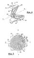
- This signal light 10 comprises an optical part full 12 which serves as both a luminous flux recuperator and a light flux diffuser for a constituted light source here of a light emitting diode 14.
- Diode 14 has been shown mounted on a circuit board. support 16 which allows in particular its connection to a network power supply and to a control unit (not shown).
- a so-called strong diode 14 is used.
- power i.e. a diode whose light power is several tens of lumens, for example greater than 30 lumens, which is to compare with the power less than 10 lumens of so-called low power diodes.
- the high power diodes 14 are available in several colors, i.e. it is possible to choose the coloring of the light flux emitted by the diode 14. Preferably, we choose the color of the diode 14 according to the function of signaling to be carried out, for example red for a function anti-fog light, or white for a reversing light function.
- the optical part 12 and the diode 14 are arranged coaxially along a central optical axis A-A which extends generally horizontally from left to right, in considering figure 6.
- the diode 14 has at the rear a connection box 18 substantially cylindrical and at the front a globe 20 substantially hemispherical centered on the optical axis A-A.
- connection box 18 includes means for fixing and electrical connection (not shown) for the mounting of the diode 14 on the plate 16.
- the optical part 12 is made of a material transparent with a higher refractive index than the air, which here constitutes the ambient environment surrounding the room 12.
- the optical part 12 is produced in a single piece by molding in transparent plastic such as, for example, polymethyl methacrylate (PMMA).
- transparent plastic such as, for example, polymethyl methacrylate (PMMA).
- the optical part 12 comprises a main body 22 which generally has a frustoconical shape, partially hollow at the front, the base of which forms its end axial before 24 and the apex of which forms its axial end rear 26.
- the optical part 12 here comprises three fixing lugs 28, 30, 32 which extend axially towards the rear, from the front axial end 24 of the main body 22.
- These three legs 28, 30, 32 are here angularly distributed in a regular manner and have, at their axial end rear, a support portion 34 which extends outwards in a substantially radial plane and which has an axial hole 36.
- the hole 36 aims to allow the fixing of the optical part 12 on a support (not shown) of the light 10, by a fixing system of known type, for example by screwing.
- the fixing lugs 28, 30, 32 serve to maintain the optical part 12 on a light support 10 and they must retain axially and radially the optical part 12 relative to the light source, here diode 14.
- the fixing of the optical part 12 on a support does not does not necessarily require that the legs 28, 30, 32 have a hole 36. Indeed, the legs 28, 30, 32 can be fixed directly on the support by crimping or welding ultrasound.
- the main body 22 of the optical part 12 is here a form of revolution around the optical axis A-A.
- the main body 22 has at its rear axial end 26 a tubular section 38.
- This tubular section 38 forms a spacer which guarantees in particular that, when the optical part 12 is mounted in axial support against the front face 40 of the plate 16, the main body 22 is not in axial abutment against the diode 14, this who could damage it.
- the tubular section 38 also serves to center the diode 14, in a radial plane, relative to the optical part 12.
- the tubular section 38 comprises, for example, three ribs centering axial 42, or gadroons, on its internal face 44, which cooperate with the cylindrical wall 46 of the connection box 18 diode 14.
- the tubular section 38 may have axial pins which are received in complementary holes made opposite in the support.
- the main body 22 has, in its axial end rear 26, a housing 48 which is intended to receive axially the globe 20 of the diode 14. More precisely, the diode 14 is arranged in the housing 48 so that its globe 20 extends entirely inside the housing 48.
- housing 48 has a generally cylindrical shape.
- Her cylindrical wall 50 defines, at its rear axial end, a shoulder surface 52 with the internal cylindrical wall 44 of the tubular section 38.
- the internal diameter of the cylindrical wall internal 44 is slightly greater than the internal diameter of the housing 48.
- the front axial end of the housing 48 is closed by a wall 54 convex (backwards) which forms a lens convergent centered on the optical axis A-A.
- the frustoconical rear face 56 is stepped radially towards outside and axially forward, here from the end axial front 60 of the tubular section 38.
- the frustoconical rear face 56 is therefore formed by a series of frustoconical surfaces 62, 64, 66, 68, 70 coaxial axially superimposed and interconnected by surfaces 72, 74, 76, 78 substantially radial and annular.
- each tapered surface 62, 64, 66, 68, 70 extends in a direction substantially inclined towards the front, i.e. from the rear to the front and from the optical axis A-A outwards.
- each frustoconical surface 62, 64, 66, 68, 70 is increasing from back to front.
- the rear surfaces frustoconical 62, 64, 66, 68, 70 will be called faces of reflection.
- the frustoconical front face 58 of the main body 22 is delimited axially at the rear by a central surface 80 substantially radial and circular, which is arranged axially in look of the lens 54.
- the diameter of the central surface 80 is here substantially equal to the diameter of the lens 54.
- the frustoconical front face 58 is stepped radially outward and axially forward.
- the tapered front face 58 is therefore formed by a series of radial annular front surfaces designated by the references 82 to 96.
- exit faces the front surfaces annulars 82 to 96 will be called exit faces.
- each outlet face 82 to 96 is linked at the outer edge of the radial surface 80 or of the outlet face 82 to 96 which is radially adjacent to it by a surface substantially cylindrical 98.
- the outlet faces 82 to 96 form a series of crowns concentric adjacent.
- the outlet faces 82 to 96 are not planar. They are each formed of a series of elementary dioptric elements 100, or dioptric patterns, adjacent.
- each element diopter 100 has the shape of an angular portion of a crown, considering the crown formed by the outlet face 82 to 96 associated.
- the dioptric elements 100 of an output face 82 to 96 determined are therefore distributed circumferentially so that they are circumferentially adjacent two by two.
- each dioptric element 100 forms a domed facet, here generally concave in profile towards the rear.
- Each dioptric element 100 is comparable to a diopter, or prism. In the present embodiment, each dioptric element 100 constitutes a divergent diopter, due of its concave profile.
- each dioptric element 100 can be convex (forward), so as to form a converging diopter.
- the form concave, or curve, of the surface forming each element diopter 100 is determined so that rays bright, directed forward, which reach the rear 102 of the dioptric element 100 in a direction substantially parallel to the optical axis A-A, emerge from the front face 104 of the dioptric element 100 by forming a beam at the front lighting carrying out the chosen signaling function.
- each element diopter 100 deflects and distributes the light rays it receives from so as to realize at the front, on a measurement screen, an image globally diamond-shaped
- the diamond is not regular. It must have a height, along the vertical axis V-V, less than its width, along the axis horizontal H-H. So, according to the angular orientation of each dioptric element 100, in a radial plane, its concave shape must be optimized to allow to realize on the screen of measures a shape that approximates the diamond sought here.
- Mathematical algorithms allow to calculate, by progressive "morphing", the appropriate form for each dioptric element 100, depending on its angular position around the optical axis A-A.
- the dioptric elements 100 belonging to outlet faces 82 to 96 different, and whose position angular with respect to the optical axis A-A is substantially identical, generally have the same concave shape.
- the central surface 80 is also formed of a series dioptric elements 100, here generally arranged in the same radial plane.
- the elements diopters 100 forming the central surface 80 are arranged along a rectangular mesh, here parallel to the vertical axis V-V.
- dioptric elements 100 of the surface central 80 which are adjacent to its circular edge 81 are rectangle portions which have an arcuate edge.
- the diode 14 is a point light source, arranged on the optical axis A-A, we assume that the light rays are emitted radially, globally forward, from center 106 of the hemisphere forming the globe 20.
- the diode 14 being of the high power type, it has an opening close to 180 degrees, i.e. it emits light rays at a solid angle of 180 degrees.
- the reflection face 62 closest to the optical axis A-A, extends axially behind the center 106 of the diode 14, so that the radius R1, which is the most rear radius, is reflected towards the front by said reflection face 62. Otherwise, the radius R1, and neighboring light rays, would be "lost" to inside the body 22, for example by refracting towards the wall outside of the tubular section 38.
- the light rays After passing through the cylindrical wall 50 of the housing, the light rays are refracted so that they "impact" against a reflection face 62 to 70 of the body 22 of the part optical 22. Arriving on the reflection faces 62 to 70, these light rays are totally reflected towards the front, in accordance with the optical principle of total reflection of the light in a medium with a higher refractive index than the air.
- a light ray "impacts" on a face of reflection 62 to 70 of body 22, with an angle of incidence sufficiently distant from an orthogonal direction, then it is totally reflected by said reflection face 62 to 70, without it be necessary for example to deposit a reflective material on said face 62 to 70.
- each reflection face 62 to 70 The inclination of the generator of each reflection face 62 to 70 is provided so that the light rays it receives are reflected forward, in a generally direction parallel to the optical axis A-A.
- the angle of inclination of the generatrices of the faces reflection 62 to 70 relative to the optical axis A-A, in the direction schedule considering figure 6, tends to decrease when we deviates from the optical axis A-A, radially outward.
- each face of reflection 62 to 70 is slightly in a convex curve, so that gradually adapt to the angle of incidence of the rays refracted which evolves according to the axial position of its place of incidence on the cylindrical wall 50.
- the rays reflected on the reflection faces 62 to 70 are therefore directed forwards, following directions generally parallel to the optical axis A-A, on the rear face 102 of dioptric elements 100 forming the output faces 82 to 96.
- the dioptric elements 100 deflect the light rays so that the light beam emitted forward from each dioptric element 100 generally forms a rhombus, in the case of a fog light.
- FIG. 6 the path of the light rays which comes to be described, is illustrated by the beam F1 and by the beam F2.
- annular radial surfaces 72, 74, 76, 78 are optically neutral surfaces, vis-à-vis the transmission of light rays inside the optical part 12. Indeed, the light rays which are refracted inside the body 22, through the cylindrical wall 50, due to their inclinations, cannot reach these radial surfaces annulars 72, 74, 76, 78.
- annular radial surfaces 72, 74, 76, 78 are not essential, because the frusto-conical rear face 56 may not be stepped and thus form only one rear face of reflection.
- the staging of the reflection faces 62 to 70 increases the outside diameter of the optical part 12, therefore the apparent luminous surface which performs the function of signaling.
- the light ray R2 which passes through the wall cylindrical 50 of the housing 48 in the vicinity of its end axial before 108, and which constitutes approximately the "Last" ray of light, starting from the rear, to cross the cylindrical wall 50, determines the minimum axial thickness of the body 22 of the optical part 12 and its external diameter.
- this light ray R2 when it refracts to the interior of the body 22 is located at the front most. Therefore, it is preferable that the outlet faces 82 to 96 are arranged axially in front of this radius R2, so that they do not are not interposed between the radius R2 and the reflection face 70 on which it is expected to reflect.
- the axial position of outlet faces 82 to 96 partly determines the axial thickness of the body 22.
- the radius R2 is reflected on the reflection face 70 radially outermost and axially outermost.
- the radius R2 determines the axial position and the position radial from the front axial end 24 of the reflection face radially outer 70, so the outer diameter and the axial depth of the body 22 of the optical part 12.
- a axial margin between the radius R2 and the outlet faces 82 to 96 In the embodiment shown here, a axial margin between the radius R2 and the outlet faces 82 to 96.
- This lens 54 here forms a converging lens which deflects incoming light rays on its rear face so that they refract inside the body 22 of the optical part 12 in a direction generally parallel to the optical axis A-A.
- harness F3 the path of the light rays which penetrate in the body 22 of the optical part 12 by the lens 54, is illustrated by harness F3.
- the luminous flux produced at the exit of the optical part 12 by the beams F1 and F2 can be called reflected flow, because its light rays have been reflected on the reflecting faces 62 to 70 of the optical part 12.
- the luminous flux produced at the exit of the optical part 12 by the beam F3 can be called direct flow, because its rays bright have not been reflected inside the room optics 12.
- the cylindrical wall 48 of the housing 50, the rear faces of reflection 62 to 70, and the lens 54 form a recuperator of luminous flow.
- the outlet front faces 80 to 96 form a distributor luminous flow.
- the signaling light 10 optimizes the use of new strong diodes power.
- the optical part 12 according to the invention allows recover the majority of the light flux emitted by the diode 14, so that the diode 14 and the optical part 12 are sufficient to satisfy photometric requirements to perform a function of regulatory signage, whereas previously it was necessary to use several diodes, in order to get to the output of the signal light sufficient light energy.
- the signaling light 10 according to the invention therefore makes it possible to perform a regulatory signaling function with a light of smaller size, which in particular facilitates the arrangement of the fire in a vehicle.
- a function of signaling determined using several optical parts 12 and several associated low power diodes.
- the diode 14 can be replaced by a lamp with filament.
- this variant requires increasing by significantly the size of the optical part 12, in particular to allow the heat produced by the filament to be dissipated.
- a large part of the luminous flux emitted by the lamp filament cannot be recovered by the optical part, without addition of an additional recovery device.
- the outlet front faces 82 to 96 are not stepped, that is to say that the body 22 of the optical part 12 has a single outlet face which forms a radial surface round arranged at the front axial end 24 of the optical part 12.
- the dioptric elements 100 are then all arranged generally in the same radial plane. These dioptric elements 100 can keep the same layout as in the realization described above, so that the appearance of the room optics 12 in front view is the same as in FIG. 5, or else the dioptric elements 100 can all be arranged according to a rectangular mesh.
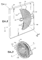
- the signaling light 10 comprises, as in the first embodiment, a light emitting diode 14 of high power which is mounted on a support plate 16, and an optical part 12 which is mounted on a support (not shown) of the signal light 10, at the front of the diode 14.
- the part optics 12 generally has a shape of revolution around the axis optical A-A on which the diode 14 is arranged.
- the optical part 12 generally has the shape of a cap spherical which is hollowed out at the back and which here has two legs support 110, 112, diametrically opposed, extending in a radial plane from the rear axial end 114 of the part optics 12.
- the support legs 110, 112 are for example similar to the bearing portions 34 of the tabs 28, 30, 32 of the optical part 12 of the first embodiment.
- the concave rear face (forward) 116 of the part optic 12 has the form of an optic type flow recuperator de Fresnel, well known in the state of the art.
- an optic type flow recuperator de Fresnel well known in the state of the art.
- the rear face 116 therefore has the shape of a lens. Fresnel, or stepped lens.
- the face rear 116 here comprises a central part 118 which is constituted of a series of converging annular diopters 120.
- the converging diopters 120 of the central part 118 are stepped radially outwards and axially towards the rear.
- the central part 118 is designed to operate in simple refraction, i.e. the light rays it receives refract inside the optical part 12 and are deviated in a direction substantially parallel to the axis optics A-A.
- the central part 118 here has a substantially equal diameter to the diameter of the connection box 18 of the diode 14.
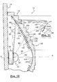
- the rear face 116 has a peripheral part annular 122 which consists of a series of diopters, or prisms, annulars 124.
- These annular diopters 124 form a tooth profile of saw on the rear side 116.
- each annular diopter 124 has an interior inlet face 126, the generator of which extends in a direction substantially parallel to the optical axis A-A, and an external reflection face 128, the generator of which extends in a direction substantially tilted forward from the rear axial end 130 of the entrance face 126.
- the angle of inclination of the reflection faces 128, with respect to the optical axis A-A increases since the annular diopters 124 near the axis A-A towards the diopters annular 124 distant from the axis A-A, so that the inclination reflection faces 128 adapts to the angle of incidence of the light rays they receive from the diode 14.
- the peripheral part 122 is designed to operate at the times in refraction, by collecting the light rays which refract on the input faces 126 of its annular diopters 124, and in reflection, by deflecting the light rays according to a direction substantially parallel to the optical axis A-A, after they are reflected on the reflection faces 128 of its diopters annulars 124.
- the face before exit 132 of the optical part 12 is formed by a series of elementary dioptric elements of distribution 100. These 100 dioptric elements are similar to those described with reference to the first embodiment.
- Each of the dioptric elements 100 here has a surface before 104 convex, so as to form a converging diopter, as in the variant embodiment shown in FIG. 7.
- the dioptric elements 100 here have a shape substantially square (in front view)
- the elements dioptrics 100 here form a rectangular mesh.
- the dioptric elements 100 can be arranged in crowns as in the first embodiment.
- the dioptric elements 100 are here radially stepped outwards and axially rearwards, thus forming stairs going down from the optical axis A-A to the outside and backwards.
- Each dioptric element 100 is therefore linked to the element diopter 100 which is radially adjacent to it by a surface 134, here substantially parallel to the axis A-A.
- the front face 132 of the optical part 12 can be globally planar, so that all dioptric elements 100 are contained globally in the same radial plane.
- the optical part 12 then has a shape generally cylindrical, with an outlet front face 132 radial and a concave rear face 116, in the shape of a cap spherical.
- the dioptric elements 100 which are arranged axially in look of the central part 118, are contained overall in the same radial plane and they thus form a central front face outlet 80.
- the spherical cap shape of the optical part 12 surrounds and covers substantially the entire globe 20 of the diode 14, so that all the light rays emitted by the diode 14 are recovered by the rear face 116 of the part optics 12.
- Each of the light rays R5, R6, R7, R8, emitted by the diode 14 on the rear face of the peripheral part 122, by example the radius R8 which is shown in detail in FIG. 11, will first refract inside the optical part 12, crossing the entry face 126 of an annular diopter 124, then it will be reflected on the associated reflection face 128 of the diopter annular 124, remaining inside the optical part 12, way to be deflected forward, in one direction substantially parallel to the optical axis A-A. He then reaches the rear face 102 of a dioptric element 100 opposite which distributed in front of the traffic light 10, so as to achieve the desired signaling function.
- this second embodiment is suitable for operate with a filament lamp to replace the diode 14, subject to increasing the dimensions of the part optical 12.
- the dimensions of the optical part 12 depending on the variant are obtained by a transformation homothetic whose relationship is related to physical differences light sources, in particular to ensure the filament lamp cooling.
- the homothety is performed in relation to the center of the light source, i.e. relative to the filament for the filament lamp and relative to the center 106 of the globe 20 for diode 14, and the coefficient of the transformation matrix retained is three, for the passage of the diode 14 towards the lamp with filament.
- the circular shape of revolution of the part optic 12 is the optimal shape which allows to recover the majority of the light flux emitted by the diode 14.
- optical part 12 for example an ellipse shape or a shape rectangular, front view or rear view.
- the part optic 12 is “autonomous” at the optical level, ie that it performs the signaling function alone, without it it is necessary to add a reflector and / or a glass diffusion.
- the optical part 12 according to the invention achieves both the recovery of the light rays emitted by the source 14 and the distribution of light rays at the front so as to achieve selected signaling function.
- the signaling light 10 according to the invention can be arranged inside a case comprising a glass external protection, for example in a case which groups together all traffic lights associated with the different functions regulations.
Landscapes
- Engineering & Computer Science (AREA)
- General Engineering & Computer Science (AREA)
- Non-Portable Lighting Devices Or Systems Thereof (AREA)
- Led Device Packages (AREA)
Abstract
Description
- une face d'entrée dont la génératrice s'étend dans une direction sensiblement parallèle à l'axe optique ;
- une face arrière de réflexion dont la génératrice s'étend dans une direction sensiblement inclinée vers l'avant ;
- et une face avant de sortie ;
caractérisé en ce que la face de sortie est formée d'une série d'éléments dioptriques élémentaires de répartition dont chacun est prévu pour former un faisceau lumineux élémentaire dont l'image, sur un écran placé à l'avant du feu de signalisation, correspond à la fonction de signalisation à réaliser.
- chaque élément dioptrique élémentaire s'étend globalement dans un plan radial, et les éléments dioptriques élémentaires forment un maillage ;
- les éléments dioptriques sont agencés en couronnes autour de l'axe optique, et chaque élément dioptrique s'étend sur une portion angulaire de couronne ;
- la pièce optique comporte plusieurs faces arrière de réflexion qui sont étagées axialement et radialement ;
- la pièce optique comporte plusieurs faces d'entrée qui sont étagées axialement vers l'arrière et radialement depuis l'axe optique vers l'extérieur ;
- la pièce optique comporte une portion centrale, au moins en partie de révolution autour de l'axe optique, qui est agencée axialement à l'avant de la source lumineuse, et qui comporte au moins une face arrière d'entrée qui est prévue pour dévier le flux lumineux entrant, selon le principe de la réfraction, pour le renvoyer, suivant une direction sensiblement parallèle à l'axe optique, vers une face avant centrale de sortie associée de la pièce optique, prévue pour former un faisceau lumineux correspondant à la fonction de signalisation à réaliser ;
- au moins une partie de la portion centrale est une lentille ;
- la pièce optique comporte un logement arrière sensiblement cylindrique et coaxial à l'axe optique dans lequel est agencée la source lumineuse ;
- la pièce optique comporte plusieurs faces arrière annulaires de réflexion qui sont étagées axialement vers l'avant et radialement depuis l'axe optique vers l'extérieur, deux faces arrière de réflexion adjacentes étant séparées par une face arrière annulaire optiquement neutre agencée en dehors du trajet du flux lumineux qui vient se réfléchir sur lesdites faces arrière de réflexion ;
- la pièce optique comporte plusieurs faces avant annulaires de sortie qui sont étagées axialement vers l'avant et radialement depuis l'axe optique vers l'extérieur ;
- la face arrière de la pièce optique a globalement la forme d'une calotte sphérique centrée sur l'axe optique ;
- la source lumineuse est une diode électroluminescente ;
- la pièce optique est réalisée en une seule pièce, notamment par moulage en matière plastique.
- la figure 1 est une vue en perspective éclatée de trois quarts avant qui représente le feu de signalisation selon un premier mode de réalisation de l'invention ;
- la figure 2 est une vue en perspective de trois quarts avant, avec arrachement, qui représente le feu de signalisation de la figure 1 ;
- la figure 3 est une vue agrandie d'un détail de la figure 2 qui représente des éléments dioptriques élémentaires ;
- la figure 4 est une vue en perspective de trois quarts arrière, avec arrachement, qui représente le feu de signalisation de la figure 1 ;
- la figure 5 est une vue de face qui représente le feu de signalisation de la figure 1 ;
- la figure 6 est une vue partielle agrandie en coupe axiale, suivant le plan de coupe 6-6 de la figure 2, qui illustre le trajet des rayons lumineux émis par la diode électroluminescente du feu de signalisation de la figure 1 ;
- la figure 7 est une vue partielle similaire à celle de la figure 6 qui représente une variante de réalisation des éléments dioptriques ;
- la figure 8 est une vue en perspective de trois quarts avant, avec arrachement, qui représente un feu de signalisation selon un deuxième mode de réalisation de l'invention ;
- la figure 9 est une vue en perspective de trois quarts arrière qui représente la pièce optique du feu de signalisation de la figure 8 ;
- la figure 10 est une vue partielle agrandie en coupe axiale, suivant le plan de coupe 10-10 de la figure 8, qui illustre le trajet des rayons lumineux émis par la diode électroluminescente du feu de signalisation de la figure 8 ;
- la figure 11 est une vue agrandie d'un détail de la figure 10 qui représente le trajet d'un rayon lumineux dans un dioptre annulaire appartenant à la partie périphérique de la face arrière du feu de signalisation de la figure 8.
Claims (13)
- Feu de signalisation (10), notamment pour un véhicule automobile, du type comportant un axe optique central (A-A) orienté de l'arrière vers l'avant, une source lumineuse (14) globalement ponctuelle disposée sur cet axe optique (A-A), et une pièce optique pleine (12), au moins en partie de révolution autour de l'axe optique (A-A), qui est réalisée dans une matière transparente d'indice de réfraction supérieur à celui de l'air, et qui est agencée à l'avant de la source (14), du type dans lequel la pièce optique (12) comporte au moins :de sorte que le flux lumineux, émis par la source (14) et pénétrant dans la pièce optique (12) par la face d'entrée (50, 126), se réfléchit sur la face arrière de réflexion (62, 64, 66, 68, 70, 128), selon le principe de la réflexion totale, et est renvoyé vers la face avant de sortie (82, 84, 86, 88, 90, 92, 94, 96, 132) suivant une direction globalement parallèle à l'axe optique (A-A), en vue de réaliser une fonction de signalisation déterminée,une face d'entrée (50, 126) dont la génératrice s'étend dans une direction sensiblement parallèle à l'axe optique (A-A) ;une face arrière de réflexion (62, 64, 66, 68, 70, 128) dont la génératrice s'étend dans une direction sensiblement inclinée vers l'avant ;et une face avant de sortie (82, 84, 86, 88, 90, 92, 94, 96, 132) ;
caractérisé en ce que la face de sortie (82, 84, 86, 88, 90, 92, 94, 96, 132) est formée d'une série d'éléments dioptriques élémentaires de répartition (100) dont chacun est prévu pour former un faisceau lumineux élémentaire dont l'image, sur un écran placé à l'avant du feu de signalisation (10), correspond à la fonction de signalisation à réaliser. - Feu de signalisation (10) selon la revendication précédente, caractérisé en ce que chaque élément dioptrique élémentaire (100) s'étend globalement dans un plan radial, et en ce que les éléments dioptriques élémentaires (100) forment un maillage.
- Feu de signalisation (10) selon la revendication 1, caractérisé en ce que les éléments dioptriques (100) sont agencés en couronnes autour de l'axe optique (A-A), et en ce que chaque élément dioptrique (100) s'étend sur une portion angulaire de couronne.
- Feu de signalisation (10) selon l'une quelconque des revendications précédentes, caractérisé en ce que la pièce optique (12) comporte plusieurs faces arrière de réflexion (62, 64, 66, 68, 70, 128) qui sont étagées axialement et radialement.
- Feu de signalisation (10) selon l'une quelconque des revendications précédentes, caractérisé en ce que la pièce optique (12) comporte plusieurs faces d'entrée (126) qui sont étagées axialement vers l'arrière et radialement depuis l'axe optique (A-A) vers l'extérieur.
- Feu de signalisation (10) selon l'une quelconque des revendications précédentes, caractérisé en ce que la pièce optique (12) comporte une portion centrale (54, 118), au moins en partie de révolution autour de l'axe optique (A-A), qui est agencée axialement à l'avant de la source lumineuse (14), et qui comporte au moins une face arrière d'entrée (54, 120) qui est prévue pour dévier le flux lumineux entrant, selon le principe de la réfraction, pour le renvoyer, suivant une direction sensiblement parallèle à l'axe optique (A-A), vers une face avant centrale de sortie (80) associée de la pièce optique (12), prévue pour former un faisceau lumineux correspondant à la fonction de signalisation à réaliser.
- Feu de signalisation (10) selon la revendication précédente, caractérisé en ce qu'au moins une partie de la face arrière d'entrée de la portion centrale (54) est une lentille.
- Feu de signalisation (10) selon l'une quelconque des revendications précédentes, caractérisé en ce que la pièce optique (12) comporte un logement arrière (48) sensiblement cylindrique et coaxial à l'axe optique (A-A) dans lequel est agencée la source lumineuse (14).
- Feu de signalisation (10) selon la revendication précédente, caractérisé en ce que la pièce optique (12) comporte plusieurs faces arrière annulaires de réflexion (62, 64, 66, 68, 70) qui sont étagées axialement vers l'avant et radialement depuis l'axe optique vers l'extérieur, deux faces arrière de réflexion (62, 64, 66, 68, 70) adjacentes étant séparées par une face arrière annulaire (72, 74, 76, 78) optiquement neutre agencée en dehors du trajet du flux lumineux qui vient se réfléchir sur lesdites faces arrière de réflexion (62, 64, 66, 68, 70).
- Feu de signalisation (10) selon la revendication précédente, caractérisé en ce que la pièce optique (12) comporte plusieurs faces avant annulaires de sortie (80, 82, 84, 86, 88, 90, 92, 94, 96) qui sont étagées axialement vers l'avant et radialement depuis l'axe optique (A-A) vers l'extérieur.
- Feu de signalisation (10) selon l'une quelconque des revendications 1 à 7, caractérisé en ce que la face arrière (116) de la pièce optique (12) a globalement la forme d'une calotte sphérique centrée sur l'axe optique (A-A).
- Feu de signalisation (10) selon l'une quelconque des revendications précédentes, caractérisé en ce que la source lumineuse est une diode électroluminescente (14).
- Feu de signalisation (10) selon l'une quelconque des revendications précédentes, caractérisé en ce que la pièce optique (12) est réalisée en une seule pièce, notamment par moulage en matière plastique.
Applications Claiming Priority (2)
| Application Number | Priority Date | Filing Date | Title |
|---|---|---|---|
| FR0202220A FR2836208B1 (fr) | 2002-02-21 | 2002-02-21 | Feu de signalisation comportant une piece optique realisant une fonction de signalisation de maniere autonome |
| FR0202220 | 2002-02-21 |
Publications (2)
| Publication Number | Publication Date |
|---|---|
| EP1338844A1 true EP1338844A1 (fr) | 2003-08-27 |
| EP1338844B1 EP1338844B1 (fr) | 2020-03-11 |
Family
ID=27636396
Family Applications (1)
| Application Number | Title | Priority Date | Filing Date |
|---|---|---|---|
| EP03290318.9A Expired - Lifetime EP1338844B1 (fr) | 2002-02-21 | 2003-02-07 | Feu de signalisation comportant une pièce optique réalisant une fonction de signalisation de manière autonome |
Country Status (4)
| Country | Link |
|---|---|
| US (1) | US6755556B2 (fr) |
| EP (1) | EP1338844B1 (fr) |
| JP (1) | JP2003281907A (fr) |
| FR (1) | FR2836208B1 (fr) |
Cited By (12)
| Publication number | Priority date | Publication date | Assignee | Title |
|---|---|---|---|---|
| FR2859423A1 (fr) * | 2003-09-05 | 2005-03-11 | Valeo Systemes Dessuyage | Module d'equipement portant un feu de signalisation arriere comportant une source de lumiere ponctuelle |
| FR2867257A1 (fr) * | 2004-03-05 | 2005-09-09 | Valeo Vision | Dispositif de signalisation et/ou d'eclairage pour vehicule automobile comportant un element dioptrique |
| WO2009141762A1 (fr) * | 2008-05-20 | 2009-11-26 | Koninklijke Philips Electronics N.V. | Élément optique pour une distribution asymétrique de la lumière |
| WO2010006971A1 (fr) * | 2008-07-16 | 2010-01-21 | Osram Gesellschaft mit beschränkter Haftung | Cadre de fixation comportant au moins un élément optique |
| DE202010006097U1 (de) | 2009-12-22 | 2010-08-05 | Automotive Lighting Reutlingen Gmbh | Lichtmodul für einen Kraftfahrzeugscheinwerfer |
| EP2587120A1 (fr) * | 2011-10-27 | 2013-05-01 | odelo GmbH | Conduit de lumière et véhicule automobile muni d'un tel conduit de lumière |
| WO2013054220A3 (fr) * | 2011-10-11 | 2013-06-13 | Koninklijke Philips Electronics N.V. | Appareil d'éclairage |
| WO2014022033A1 (fr) * | 2012-08-03 | 2014-02-06 | GE Lighting Solutions, LLC | Réflecteur omnidirectionnel comportant une surface tronconique pour une diode électroluminescente |
| EP2713095A3 (fr) * | 2012-09-26 | 2017-11-15 | Coretronic Corporation | Appareil d'éclairage de véhicule |
| FR3051413A1 (fr) * | 2016-05-19 | 2017-11-24 | Valeo Vision | Procede d'etalonnage d'un dispositif lumineux |
| EP3835650A1 (fr) * | 2019-12-09 | 2021-06-16 | ZKW Group GmbH | Corps optique pour un phare de véhicule automobile |
| DE102024210489A1 (de) | 2024-10-30 | 2026-04-30 | Aumovio Germany Gmbh | Anzeigevorrichtung und Fortbewegungsmittel |
Families Citing this family (149)
| Publication number | Priority date | Publication date | Assignee | Title |
|---|---|---|---|---|
| DE10249113B4 (de) * | 2002-10-22 | 2010-04-08 | Odelo Gmbh | Fahrzeugleuchte, insbesondere Heckleuchte, vorzugsweise für Kraftfahrzeuge |
| JP4182783B2 (ja) * | 2003-03-14 | 2008-11-19 | 豊田合成株式会社 | Ledパッケージ |
| FR2853392B1 (fr) * | 2003-04-04 | 2006-06-16 | Sli Miniature Lighting Sa | Feu arriere, en particulier feu stop pour vehicule automobile |
| US8075147B2 (en) * | 2003-05-13 | 2011-12-13 | Light Prescriptions Innovators, Llc | Optical device for LED-based lamp |
| US7329029B2 (en) * | 2003-05-13 | 2008-02-12 | Light Prescriptions Innovators, Llc | Optical device for LED-based lamp |
| DE10329185A1 (de) * | 2003-06-27 | 2005-01-20 | Guido Kellermann Produktentwicklung & Handel | Leuchte für ein Fahrzeug |
| US20050007346A1 (en) * | 2003-07-11 | 2005-01-13 | Guolin Ma | Optical conduit for channeling light onto a surface |
| DE10340040A1 (de) * | 2003-08-28 | 2005-03-31 | Schefenacker Vision Systems Germany Gmbh & Co. Kg | Beleuchtungseinheit mit Lichtleitkörper und integrierter optischer Linse |
| US7344266B2 (en) * | 2003-11-03 | 2008-03-18 | Perry Coman | Portable radial projection light source arrangement |
| JP4534074B2 (ja) * | 2003-11-27 | 2010-09-01 | 青木電器工業株式会社 | 高輝度led発光部 |
| DE602004024710D1 (de) * | 2003-12-10 | 2010-01-28 | Okaya Electric Industry Co | Anzeigelampe |
| FR2864204B1 (fr) * | 2003-12-19 | 2006-10-27 | Valeo Vision | Dispositif de signalisation ou d'eclairage, en particulier pour vehicule automobile |
| JP4497348B2 (ja) * | 2004-01-13 | 2010-07-07 | 株式会社小糸製作所 | 車両用灯具 |
| FR2870083B1 (fr) | 2004-05-10 | 2006-07-14 | Sli Miniature Lighting Sa Sa | Dispositif de maintien et de connexion de composants optoelectroniques comme les leds du type plcc2 et plcc4 |
| FR2870323B1 (fr) * | 2004-05-13 | 2006-08-04 | Valeo Vision Sa | Dispositif d'eclairage ou de signalisation comportant une piece optique qui realise un faisceau reglementaire de maniere autonome |
| DE102004026530B3 (de) * | 2004-05-29 | 2006-02-02 | Fer Fahrzeugelektrik Gmbh | Optikkörper |
| ES1058053Y (es) * | 2004-07-14 | 2005-02-01 | Fed Signal Vama Sa | Lente colimadora de reflexion interna |
| EP1789824A4 (fr) * | 2004-08-23 | 2009-01-21 | Optical Res Associates | Systemes d'eclairage conçus pour produire differentes formes de faisceaux |
| DE102004042125B4 (de) * | 2004-08-30 | 2008-05-08 | Schefenacker Vision Systems Germany Gmbh & Co. Kg | Leuchteinheit mit einer Vielzahl gekrümmter Flächenelemente |
| US7168839B2 (en) * | 2004-09-20 | 2007-01-30 | Visteon Global Technologies, Inc. | LED bulb |
| KR101214934B1 (ko) * | 2005-01-27 | 2012-12-24 | 삼성디스플레이 주식회사 | 광학 렌즈, 이를 갖는 광학 모듈, 이를 갖는 백라이트어셈블리 및 이를 갖는 표시장치 |
| ATE453930T1 (de) * | 2004-10-14 | 2010-01-15 | Fiat Ricerche | Optikelement und modul zur projektion eines lichtbündels, und kraftfahrzeugleuchte mit einer mehrzahl solcher modulen |
| TWD110894S1 (zh) * | 2004-10-22 | 2006-05-11 | 東芝照明技術股份有限公司 | 照明用發光二極體透鏡 |
| FR2878020B1 (fr) * | 2004-11-18 | 2008-12-19 | Valeo Vision Sa | Dispositif d'eclairage et/ou de signalisation pour automobile produisant un faisceau lumineux sur le cote d'un vehicule automobile |
| TWM275418U (en) * | 2004-12-03 | 2005-09-11 | Chip Hope Co Ltd | Lens with light uniformization |
| MX2007006641A (es) * | 2004-12-03 | 2008-02-22 | Acuity Brands Inc | Reflector de luminaria con brida modificadora de luz. |
| KR101119193B1 (ko) | 2004-12-30 | 2012-03-22 | 삼성전자주식회사 | 광원 유닛 및 이를 갖는 액정 표시 장치 |
| US7275849B2 (en) * | 2005-02-25 | 2007-10-02 | Visteon Global Technologies, Inc. | LED replacement bulb |
| JP2006243603A (ja) * | 2005-03-07 | 2006-09-14 | Sanyo Electric Co Ltd | 集光素子及び照明装置及び投写型映像表示装置 |
| WO2006109113A2 (fr) * | 2005-04-12 | 2006-10-19 | Acol Technologies Sa | Optique primaire pour diode electroluminescente |
| JP2006339320A (ja) * | 2005-05-31 | 2006-12-14 | Omron Corp | 発光光源及び発光光源における光の出射方法 |
| US7588358B1 (en) * | 2005-05-31 | 2009-09-15 | Innovative Lighting, Inc | Single LED and lens assembly |
| JP4376289B2 (ja) | 2005-06-01 | 2009-12-02 | シーシーエス株式会社 | 光照射装置 |
| FR2887997B1 (fr) * | 2005-06-30 | 2008-04-11 | Valeo Vision Sa | Embout de guide optique a etalement des rayons lumineux |
| DE102005031777B4 (de) * | 2005-07-07 | 2021-03-11 | HELLA GmbH & Co. KGaA | Signalleuchte für Fahrzeuge mit einem gekrümmten Optikelement, das versetzte Prismen aufweist |
| KR20070013469A (ko) * | 2005-07-26 | 2007-01-31 | 삼성전자주식회사 | 광학렌즈 및 광학 패키지와, 이를 갖는 백라이트 어셈블리및 표시장치 |
| US7207700B2 (en) * | 2005-09-22 | 2007-04-24 | Visteon Global Technologies, Inc. | Near field lens with spread characteristics |
| US7401948B2 (en) * | 2005-10-17 | 2008-07-22 | Visteon Global Technologies, Inc. | Near field lens having reduced size |
| US7160010B1 (en) | 2005-11-15 | 2007-01-09 | Visteon Global Technologies, Inc. | Light manifold for automotive light module |
| US7489453B2 (en) * | 2005-11-15 | 2009-02-10 | Visteon Global Technologies, Inc. | Side emitting near field lens |
| US7564070B2 (en) * | 2005-11-23 | 2009-07-21 | Visteon Global Technologies, Inc. | Light emitting diode device having a shield and/or filter |
| US7438454B2 (en) * | 2005-11-29 | 2008-10-21 | Visteon Global Technologies, Inc. | Light assembly for automotive lighting applications |
| US8044585B2 (en) * | 2006-05-02 | 2011-10-25 | Chain Technology Consultant Inc. | Light emitting diode with bumps |
| JP2007325883A (ja) * | 2006-06-09 | 2007-12-20 | Aruze Corp | 遊技機及び遊技機用表示装置 |
| US7733580B2 (en) * | 2006-11-06 | 2010-06-08 | Panasonic Corporation | Light emitting module and light receiving module |
| JP5078419B2 (ja) * | 2006-11-06 | 2012-11-21 | パナソニック株式会社 | 発光モジュールおよび受光モジュール |
| JP2008166024A (ja) * | 2006-12-27 | 2008-07-17 | Toyoda Gosei Co Ltd | 車両用灯具 |
| EP1947382A1 (fr) * | 2007-01-19 | 2008-07-23 | Valeo Vision | Module d'éclairage ou de signalisation d'aspect amélioré |
| JP4799433B2 (ja) * | 2007-01-31 | 2011-10-26 | 株式会社小糸製作所 | 車両用灯具 |
| US7554742B2 (en) * | 2007-04-17 | 2009-06-30 | Visteon Global Technologies, Inc. | Lens assembly |
| US7703950B2 (en) * | 2007-11-21 | 2010-04-27 | C-R Control Systems, Inc. | Side-emitting lens for LED lamp |
| JP4557037B2 (ja) * | 2008-04-08 | 2010-10-06 | ウシオ電機株式会社 | Led光放射装置 |
| DE102008023551B4 (de) | 2008-05-14 | 2019-05-09 | Automotive Lighting Reutlingen Gmbh | Beleuchtungseinrichtung in Form eines Projektionsscheinwerfers für Kraftfahrzeuge |
| US7766509B1 (en) * | 2008-06-13 | 2010-08-03 | Lumec Inc. | Orientable lens for an LED fixture |
| FR2934031B1 (fr) * | 2008-07-21 | 2020-01-31 | Valeo Vision S.A.S | Module d'eclairage ou de signalisation d'aspect tridimensionnel ameliore |
| US8068288B1 (en) * | 2008-09-15 | 2011-11-29 | Triformix, Inc. | Thin stepped tulip lens |
| US8075165B2 (en) * | 2008-10-14 | 2011-12-13 | Ledengin, Inc. | Total internal reflection lens and mechanical retention and locating device |
| US8449150B2 (en) * | 2009-02-03 | 2013-05-28 | Osram Sylvania Inc. | Tir lens for light emitting diodes |
| JP5369359B2 (ja) * | 2009-04-13 | 2013-12-18 | スタンレー電気株式会社 | 灯具 |
| KR101001953B1 (ko) | 2009-08-31 | 2010-12-20 | 정창국 | 확산각도를 조절하는 광 가이드 유닛 및 이를 포함하는 led 램프 |
| TWI396310B (zh) * | 2009-10-02 | 2013-05-11 | 億光電子工業股份有限公司 | 發光二極體結構 |
| JP5023134B2 (ja) * | 2009-10-27 | 2012-09-12 | 株式会社遠藤照明 | Led配光レンズ、そのled配光レンズを備えたled照明モジュール及びそのled照明モジュールを備えた照明器具 |
| US8434914B2 (en) * | 2009-12-11 | 2013-05-07 | Osram Sylvania Inc. | Lens generating a batwing-shaped beam distribution, and method therefor |
| US20110141729A1 (en) | 2009-12-11 | 2011-06-16 | Osram Sylvania Inc. | Retrofit-Style Lamp and Fixture, Each Including a One-Dimensional Linear Batwing Lens |
| US20110140589A1 (en) * | 2009-12-15 | 2011-06-16 | Futur-Tec (Hong Kong) Limited | Led lamp configured to project a substantially homegenous light pattern |
| CZ309346B6 (cs) * | 2010-11-01 | 2022-09-14 | Varroc Lighting Systems, s.r.o. | Světlovodný modul se seřiditelným osvětlením povrchu obrysu |
| US20110228528A1 (en) * | 2010-03-17 | 2011-09-22 | Osram Sylvania Inc. | Retrofit-style lamp and fixture, each including a one-dimensional linear batwing lens |
| JP5441801B2 (ja) * | 2010-04-12 | 2014-03-12 | 株式会社小糸製作所 | 車両用灯具 |
| JP5523204B2 (ja) * | 2010-05-26 | 2014-06-18 | 株式会社小糸製作所 | 車両用灯具 |
| JP5596418B2 (ja) * | 2010-06-01 | 2014-09-24 | 株式会社小糸製作所 | 車両用灯具 |
| JP5507370B2 (ja) * | 2010-07-20 | 2014-05-28 | スタンレー電気株式会社 | 車両用灯具 |
| DE102010049422A1 (de) * | 2010-10-23 | 2012-04-26 | Automotive Lighting Reutlingen Gmbh | Beleuchtungseinrichtung für ein Kraftfahrzeug |
| US8267553B2 (en) * | 2010-11-01 | 2012-09-18 | Amtai Medical Equipment, Inc. | LED illuminant module for medical luminaires |
| DE102011015405A1 (de) | 2011-03-29 | 2012-10-04 | Osram Opto Semiconductors Gmbh | Optisches Element und strahlungsemittierende Vorrichtung mit einem derartigen optischen Element |
| CN102777786B (zh) * | 2011-05-05 | 2017-01-18 | 硅谷光擎 | 用于小型高功率发射器的点tir透镜系统 |
| TWI426208B (zh) * | 2011-08-01 | 2014-02-11 | Univ Kun Shan | 導光模組與發光裝置 |
| CN103090210B (zh) * | 2011-11-03 | 2015-07-01 | 象水国际股份有限公司 | 发光装置及其灯具的制作方法 |
| USD691321S1 (en) * | 2012-04-28 | 2013-10-08 | Foxconn Technology Co., Ltd. | Lens |
| TWI479106B (zh) * | 2012-06-18 | 2015-04-01 | B & M Optics Co Ltd | 光學透鏡 |
| CN102734673B (zh) * | 2012-06-26 | 2014-08-13 | 深圳市朗恒电子有限公司 | 一种led照明模块 |
| FR2993633B1 (fr) * | 2012-07-23 | 2018-12-07 | Valeo Vision | Guide de lumiere pour un dispositif d'eclairage et/ou de signalisation de vehicule automobile |
| WO2014020475A1 (fr) * | 2012-07-30 | 2014-02-06 | Koninklijke Philips N.V. | Lentille de type fresnel pour applications d'éclairage |
| DE102013108560A1 (de) * | 2012-08-10 | 2014-02-13 | Samsung Electronics Co., Ltd. | Beleuchtungsvorrichtung |
| JP6131571B2 (ja) * | 2012-11-13 | 2017-05-24 | 市光工業株式会社 | 車両用灯具 |
| DE102012221389B4 (de) * | 2012-11-22 | 2019-08-22 | Automotive Lighting Reutlingen Gmbh | Kraftfahrzeugleuchte mit einem Lichtleiter und einer durch den Lichtleiter hindurch sichtbaren Blende |
| KR101467638B1 (ko) * | 2012-12-13 | 2014-12-04 | 엘지이노텍 주식회사 | 확산 렌즈, 이를 갖는 엘이디 어레이 바 및 이를 갖는 백라이트 어셈블리 |
| US9869432B2 (en) | 2013-01-30 | 2018-01-16 | Cree, Inc. | Luminaires using waveguide bodies and optical elements |
| US9366396B2 (en) | 2013-01-30 | 2016-06-14 | Cree, Inc. | Optical waveguide and lamp including same |
| US9625638B2 (en) | 2013-03-15 | 2017-04-18 | Cree, Inc. | Optical waveguide body |
| US9291320B2 (en) | 2013-01-30 | 2016-03-22 | Cree, Inc. | Consolidated troffer |
| US9442243B2 (en) | 2013-01-30 | 2016-09-13 | Cree, Inc. | Waveguide bodies including redirection features and methods of producing same |
| US10436969B2 (en) | 2013-01-30 | 2019-10-08 | Ideal Industries Lighting Llc | Optical waveguide and luminaire incorporating same |
| US9690029B2 (en) * | 2013-01-30 | 2017-06-27 | Cree, Inc. | Optical waveguides and luminaires incorporating same |
| US10355182B2 (en) * | 2013-03-13 | 2019-07-16 | Lumileds Llc | Encapsulated LED lens with bottom reflectors |
| US9677738B2 (en) * | 2013-03-15 | 2017-06-13 | 1947796 Ontario Inc. | Optical device and system for solid-state lighting |
| US9798072B2 (en) | 2013-03-15 | 2017-10-24 | Cree, Inc. | Optical element and method of forming an optical element |
| US10436970B2 (en) | 2013-03-15 | 2019-10-08 | Ideal Industries Lighting Llc | Shaped optical waveguide bodies |
| US10502899B2 (en) * | 2013-03-15 | 2019-12-10 | Ideal Industries Lighting Llc | Outdoor and/or enclosed structure LED luminaire |
| US10379278B2 (en) * | 2013-03-15 | 2019-08-13 | Ideal Industries Lighting Llc | Outdoor and/or enclosed structure LED luminaire outdoor and/or enclosed structure LED luminaire having outward illumination |
| US10209429B2 (en) | 2013-03-15 | 2019-02-19 | Cree, Inc. | Luminaire with selectable luminous intensity pattern |
| US9366799B2 (en) | 2013-03-15 | 2016-06-14 | Cree, Inc. | Optical waveguide bodies and luminaires utilizing same |
| USD698991S1 (en) * | 2013-05-31 | 2014-02-04 | Continental Manufacturing, LLC | Lighting fixture lens |
| EP2835575A3 (fr) | 2013-08-06 | 2015-03-25 | Farba Otomotiv Aydinlatma ve Plastik Fabrikalari Anonim Sirketi | Élément optique avec réflexion totale |
| US10295153B2 (en) * | 2013-08-22 | 2019-05-21 | Signify Holding B.V. | Optical system for producing uniform illumination |
| WO2015031069A1 (fr) | 2013-08-26 | 2015-03-05 | Micropac Industries, Inc. | Régulateur d'alimentation |
| CN104421683A (zh) * | 2013-08-27 | 2015-03-18 | 鸿富锦精密工业(深圳)有限公司 | 光源模组 |
| USD719700S1 (en) * | 2013-10-24 | 2014-12-16 | Aether Systems Inc. | Optical lens for light emitting device |
| US9651740B2 (en) | 2014-01-09 | 2017-05-16 | Cree, Inc. | Extraction film for optical waveguide and method of producing same |
| US20160169477A9 (en) * | 2014-03-30 | 2016-06-16 | Khatod Optoelectronics Srl | Reflector for a led light source and related led lighting device |
| JP6425415B2 (ja) * | 2014-05-02 | 2018-11-21 | 株式会社エンプラス | 光束制御部材、発光装置および照明装置 |
| US10935211B2 (en) * | 2014-05-30 | 2021-03-02 | Ideal Industries Lighting Llc | LED luminaire with a smooth outer dome and a cavity with a ridged inner surface |
| US12372219B2 (en) * | 2014-05-30 | 2025-07-29 | Cree Lighting Usa Llc | LED luminaire with a cavity, finned interior, and a curved outer wall extending from a surface on which the light source is mounted |
| KR101622095B1 (ko) * | 2014-06-02 | 2016-05-18 | 현대모비스 주식회사 | 자동차의 조명 장치 |
| EP3166686A1 (fr) * | 2014-07-08 | 2017-05-17 | Philips Lighting Holding B.V. | Dispositif d'éclairage pour coupler la lumière provenant d'une source de lumière dans une plaque de guidage de lumière |
| KR102300558B1 (ko) * | 2014-12-26 | 2021-09-14 | 삼성전자주식회사 | 광원 모듈 |
| CN205244911U (zh) * | 2015-03-12 | 2016-05-18 | 浚洸光学科技股份有限公司 | 照明装置及其光学构件 |
| USD771172S1 (en) * | 2015-08-28 | 2016-11-08 | Chun Kuang Optics Corp. | Lens |
| US10161591B2 (en) | 2015-08-31 | 2018-12-25 | Osram Sylvania Inc. | Thin wall internal reflection light optic |
| GB2547655A (en) * | 2016-02-23 | 2017-08-30 | Plumen Ltd | A light unit |
| US10416377B2 (en) | 2016-05-06 | 2019-09-17 | Cree, Inc. | Luminaire with controllable light emission |
| US11719882B2 (en) | 2016-05-06 | 2023-08-08 | Ideal Industries Lighting Llc | Waveguide-based light sources with dynamic beam shaping |
| DE102016109647B4 (de) * | 2016-05-25 | 2022-08-25 | OSRAM Opto Semiconductors Gesellschaft mit beschränkter Haftung | Linse und Leuchte mit einer solchen Linse |
| USD809188S1 (en) * | 2016-08-18 | 2018-01-30 | Shanghai Dakin Optoelectronic Technology Co., Ltd. | Lens |
| DE102017101192A1 (de) | 2017-01-23 | 2018-07-26 | Osram Gmbh | Lichtleiter, optische Anordnung und Leuchte |
| US10344961B2 (en) * | 2017-08-17 | 2019-07-09 | Leedarson America Inc. | Optical apparatus |
| TWM558200U (zh) * | 2017-11-01 | 2018-04-11 | Depo Auto Parts Ind Co Ltd | 光學元件及汽車車燈 |
| DE102017220375A1 (de) * | 2017-11-15 | 2019-05-16 | Osram Gmbh | Tir-linse und beleuchtungsvorrichtung |
| US10838219B2 (en) * | 2018-03-21 | 2020-11-17 | Xiamen Eco Lighting Co. Ltd. | Light apparatus for generating light beams with multiple lens |
| CN110657399B (zh) * | 2018-06-29 | 2025-11-04 | 法雷奥市光(中国)车灯有限公司 | 配光构件、照明或信号指示装置和机动车辆 |
| US10739513B2 (en) | 2018-08-31 | 2020-08-11 | RAB Lighting Inc. | Apparatuses and methods for efficiently directing light toward and away from a mounting surface |
| JP7243114B2 (ja) * | 2018-10-04 | 2023-03-22 | 市光工業株式会社 | 車両用灯具 |
| US10871271B2 (en) * | 2018-10-05 | 2020-12-22 | Tempo Industries, Llc | Diverging TIR facet LED optics producing narrow beams with color consistency |
| US10801679B2 (en) | 2018-10-08 | 2020-10-13 | RAB Lighting Inc. | Apparatuses and methods for assembling luminaires |
| US10950743B2 (en) | 2019-05-02 | 2021-03-16 | Stmicroelectronics (Research & Development) Limited | Time of flight (TOF) sensor with transmit optic providing for reduced parallax effect |
| US11346542B2 (en) * | 2019-06-13 | 2022-05-31 | Apple Inc. | Electronic device with diffusively illuminated housing portions |
| US11112089B2 (en) * | 2019-06-28 | 2021-09-07 | Signify Holding B.V. | Two stage optic for LED devices |
| KR102720067B1 (ko) * | 2019-08-29 | 2024-10-21 | 현대모비스 주식회사 | 차량용 램프의 이너렌즈 |
| USD977703S1 (en) * | 2020-03-09 | 2023-02-07 | Ledil Oy | Light diffuser |
| WO2021209492A1 (fr) * | 2020-04-15 | 2021-10-21 | CommScope Connectivity Belgium BV | Dispositif et procédé de scellement de câbles dans des enceintes de télécommunications |
| USD976475S1 (en) * | 2020-05-28 | 2023-01-24 | Ledil Oy | Light diffuser |
| CN111520682A (zh) * | 2020-06-05 | 2020-08-11 | 江苏擎天车业科技有限公司 | 一种高配前组合灯 |
| DE112021003593T5 (de) | 2020-07-02 | 2023-04-20 | Magwerks Vision Inc. | Einheitliche Mehrfachoptiksysteme mit Lichtschranken |
| KR20220037645A (ko) | 2020-09-18 | 2022-03-25 | 에스엘 주식회사 | 차량용 램프 |
| USD988541S1 (en) * | 2020-10-02 | 2023-06-06 | Daniel Cortavitarte Pérez | Draft excluder for doors and windows |
| US20240093856A1 (en) * | 2021-01-26 | 2024-03-21 | Rensselaer Polytechnic Institute | 3d printable lens structure |
| CN118715400A (zh) | 2022-02-17 | 2024-09-27 | 昕诺飞控股有限公司 | 用于灯的透镜 |
| CN219177544U (zh) * | 2023-02-08 | 2023-06-13 | 中山市瑞臣电子有限公司 | 一种led光源用的新型的透镜及其投影灯 |
| US11859787B1 (en) * | 2023-02-14 | 2024-01-02 | T.Y.C. Brother Industrial Co., Ltd. | Adaptive headlamp device |
| JP2024139500A (ja) * | 2023-03-27 | 2024-10-09 | セイコーエプソン株式会社 | 電子機器、光反射部材及び表示灯 |
Citations (7)
| Publication number | Priority date | Publication date | Assignee | Title |
|---|---|---|---|---|
| US2254961A (en) * | 1937-08-21 | 1941-09-02 | George M Cressaty | Unitary lens system |
| US3821590A (en) * | 1971-03-29 | 1974-06-28 | Northern Electric Co | Encapsulated solid state light emitting device |
| FR2507741A1 (fr) | 1981-06-11 | 1982-12-17 | Cibie Projecteurs | Perfectionnements aux systemes recuperateurs de flux lumineux, notamment pour l'eclairage et la signalisation automobiles |
| US5704709A (en) * | 1995-08-25 | 1998-01-06 | Reitter & Schefenacker Gmbh & Co. Kg | Optical receiving body for at least one LED |
| DE19728354A1 (de) * | 1997-07-03 | 1999-01-07 | Sidler Gmbh & Co | Vorsatz für eine Leuchtdiode und Bremsleuchte für ein Kraftfahrzeug |
| EP1118813A2 (fr) * | 2000-01-21 | 2001-07-25 | Stanley Electric Co., Ltd. | Feu de signalisation pour véhicule automobile |
| WO2002033449A2 (fr) * | 2000-10-17 | 2002-04-25 | Osram Opto Semiconductors Gmbh | Dispositif optique |
Family Cites Families (9)
| Publication number | Priority date | Publication date | Assignee | Title |
|---|---|---|---|---|
| BE435284A (fr) * | ||||
| FR2472135A1 (fr) * | 1979-12-20 | 1981-06-26 | Cibie Projecteurs | Projecteur, notamment pour vehicules automobiles |
| FR2546607B1 (fr) * | 1983-05-25 | 1986-03-14 | Cibie Projecteurs | Perfectionnements aux feux de vehicules automobiles |
| IT8552911U1 (it) * | 1985-01-28 | 1986-07-28 | Comind Spa | Fanale di segnalazione a luce colorata per autoveicoli. |
| DE19507234B4 (de) * | 1995-03-02 | 2005-06-16 | Fer Fahrzeugelektrik Gmbh | Fahrzeugsignalleuchte mit mehreren Leuchtdioden |
| US5894196A (en) * | 1996-05-03 | 1999-04-13 | Mcdermott; Kevin | Angled elliptical axial lighting device |
| US6097549A (en) * | 1997-08-12 | 2000-08-01 | Breault Research Organization, Inc. | Bireflective lens element |
| JP2945376B1 (ja) * | 1998-05-01 | 1999-09-06 | スタンレー電気株式会社 | 灯 具 |
| US6547423B2 (en) * | 2000-12-22 | 2003-04-15 | Koninklijke Phillips Electronics N.V. | LED collimation optics with improved performance and reduced size |
-
2002
- 2002-02-21 FR FR0202220A patent/FR2836208B1/fr not_active Expired - Lifetime
-
2003
- 2003-02-07 EP EP03290318.9A patent/EP1338844B1/fr not_active Expired - Lifetime
- 2003-02-20 JP JP2003042362A patent/JP2003281907A/ja active Pending
- 2003-02-21 US US10/371,305 patent/US6755556B2/en not_active Expired - Lifetime
Patent Citations (7)
| Publication number | Priority date | Publication date | Assignee | Title |
|---|---|---|---|---|
| US2254961A (en) * | 1937-08-21 | 1941-09-02 | George M Cressaty | Unitary lens system |
| US3821590A (en) * | 1971-03-29 | 1974-06-28 | Northern Electric Co | Encapsulated solid state light emitting device |
| FR2507741A1 (fr) | 1981-06-11 | 1982-12-17 | Cibie Projecteurs | Perfectionnements aux systemes recuperateurs de flux lumineux, notamment pour l'eclairage et la signalisation automobiles |
| US5704709A (en) * | 1995-08-25 | 1998-01-06 | Reitter & Schefenacker Gmbh & Co. Kg | Optical receiving body for at least one LED |
| DE19728354A1 (de) * | 1997-07-03 | 1999-01-07 | Sidler Gmbh & Co | Vorsatz für eine Leuchtdiode und Bremsleuchte für ein Kraftfahrzeug |
| EP1118813A2 (fr) * | 2000-01-21 | 2001-07-25 | Stanley Electric Co., Ltd. | Feu de signalisation pour véhicule automobile |
| WO2002033449A2 (fr) * | 2000-10-17 | 2002-04-25 | Osram Opto Semiconductors Gmbh | Dispositif optique |
Cited By (18)
| Publication number | Priority date | Publication date | Assignee | Title |
|---|---|---|---|---|
| FR2859423A1 (fr) * | 2003-09-05 | 2005-03-11 | Valeo Systemes Dessuyage | Module d'equipement portant un feu de signalisation arriere comportant une source de lumiere ponctuelle |
| FR2867257A1 (fr) * | 2004-03-05 | 2005-09-09 | Valeo Vision | Dispositif de signalisation et/ou d'eclairage pour vehicule automobile comportant un element dioptrique |
| WO2009141762A1 (fr) * | 2008-05-20 | 2009-11-26 | Koninklijke Philips Electronics N.V. | Élément optique pour une distribution asymétrique de la lumière |
| WO2010006971A1 (fr) * | 2008-07-16 | 2010-01-21 | Osram Gesellschaft mit beschränkter Haftung | Cadre de fixation comportant au moins un élément optique |
| CN102099620A (zh) * | 2008-07-16 | 2011-06-15 | 奥斯兰姆有限公司 | 具有至少一个光学元件的保持框架 |
| DE202010006097U1 (de) | 2009-12-22 | 2010-08-05 | Automotive Lighting Reutlingen Gmbh | Lichtmodul für einen Kraftfahrzeugscheinwerfer |
| EP2338729A1 (fr) | 2009-12-22 | 2011-06-29 | Automotive Lighting Reutlingen GmbH | Module de lumière pour un phare de véhicule automobile |
| WO2013054220A3 (fr) * | 2011-10-11 | 2013-06-13 | Koninklijke Philips Electronics N.V. | Appareil d'éclairage |
| CN103858034A (zh) * | 2011-10-11 | 2014-06-11 | 皇家飞利浦有限公司 | 照明装置 |
| EP2587120A1 (fr) * | 2011-10-27 | 2013-05-01 | odelo GmbH | Conduit de lumière et véhicule automobile muni d'un tel conduit de lumière |
| WO2014022033A1 (fr) * | 2012-08-03 | 2014-02-06 | GE Lighting Solutions, LLC | Réflecteur omnidirectionnel comportant une surface tronconique pour une diode électroluminescente |
| EP2880484A1 (fr) * | 2012-08-03 | 2015-06-10 | GE Lighting Solutions, LLC | Réflecteur omnidirectionnel comportant une surface tronconique pour une diode électroluminescente |
| CN104755988A (zh) * | 2012-08-03 | 2015-07-01 | 通用电气照明解决方案有限责任公司 | 用于发光二极管的包括截头锥形表面的全向反射器 |
| CN104755988B (zh) * | 2012-08-03 | 2017-07-28 | 通用电气照明解决方案有限责任公司 | 用于发光二极管的包括截头锥形表面的全向反射器 |
| EP2713095A3 (fr) * | 2012-09-26 | 2017-11-15 | Coretronic Corporation | Appareil d'éclairage de véhicule |
| FR3051413A1 (fr) * | 2016-05-19 | 2017-11-24 | Valeo Vision | Procede d'etalonnage d'un dispositif lumineux |
| EP3835650A1 (fr) * | 2019-12-09 | 2021-06-16 | ZKW Group GmbH | Corps optique pour un phare de véhicule automobile |
| DE102024210489A1 (de) | 2024-10-30 | 2026-04-30 | Aumovio Germany Gmbh | Anzeigevorrichtung und Fortbewegungsmittel |
Also Published As
| Publication number | Publication date |
|---|---|
| EP1338844B1 (fr) | 2020-03-11 |
| US6755556B2 (en) | 2004-06-29 |
| FR2836208A1 (fr) | 2003-08-22 |
| FR2836208B1 (fr) | 2004-09-03 |
| JP2003281907A (ja) | 2003-10-03 |
| US20030156417A1 (en) | 2003-08-21 |
Similar Documents
| Publication | Publication Date | Title |
|---|---|---|
| EP1338844B1 (fr) | Feu de signalisation comportant une pièce optique réalisant une fonction de signalisation de manière autonome | |
| EP1857732B1 (fr) | Dispositif d'éclairage et/ou de signalisation pour véhicule automobile | |
| EP1416220A1 (fr) | Feu de signalisation comportant un dispositif optique de récupération et de répartition du flux lumineux vers un réflecteur annulaire | |
| EP0862016B1 (fr) | Dispositif pour rendre au moins un jet d'eau lumineux | |
| EP1288562B1 (fr) | Dispositif d'éclairage ou de signalisation pour véhicule automobile | |
| EP3167226B1 (fr) | Module lumineux d'un véhicule automobile | |
| EP3708904A1 (fr) | Dispositif lumineux imageant les surfaces eclairees d'au moins deux collecteurs | |
| EP2230446B1 (fr) | Dispositif d'éclairage ou de signalisation pour véhicule automobile | |
| FR2772115A1 (fr) | Illuminateur de surface | |
| EP3415810A1 (fr) | Système d'éclairage pour projecteur de véhicule automobile | |
| FR3039629A1 (fr) | Dispositif d'eclairage pour projecteur de vehicule automobile | |
| EP3246620A1 (fr) | Projecteur à led à dioptre créant coupure pour véhicules | |
| EP2703852A1 (fr) | Nappe de guidage de lumière avec couplage d'entrée et dioptre à surface de fresnel | |
| EP1367318B1 (fr) | Feu de signalisation comportant une pièce optique réalisant une fonction de signalisation de manière autonome | |
| EP3453955B1 (fr) | Module lumineux pour l'eclairage et/ou la signalisation d'un vehicule automobile | |
| EP3329181B1 (fr) | Système optique de collimation non-imageur d'intensité lumineuse maximale | |
| EP3623222A1 (fr) | Système optique compact pour habitacle de véhicule automobile | |
| WO2022269095A1 (fr) | Module optique d'un système lumineux d'un véhicule automobile | |
| FR2867257A1 (fr) | Dispositif de signalisation et/ou d'eclairage pour vehicule automobile comportant un element dioptrique | |
| EP1039215B1 (fr) | Feu de signalisation multi-sources perfectionné pour véhicule automobile | |
| FR2474979A1 (fr) | Dispositif d'eclairage arriere de marche arriere pour vehicules automobiles | |
| WO2025132840A1 (fr) | Unite lumineuse pour vehicule automobile | |
| FR3165711A1 (fr) | Dispositif optique pour un dispositif de signalisation lumineuse de véhicule | |
| WO2016166461A1 (fr) | Système optique imageant |
Legal Events
| Date | Code | Title | Description |
|---|---|---|---|
| PUAI | Public reference made under article 153(3) epc to a published international application that has entered the european phase |
Free format text: ORIGINAL CODE: 0009012 |
|
| AK | Designated contracting states |
Designated state(s): AT BE BG CH CY CZ DE DK EE ES FI FR GB GR HU IE IT LI LU MC NL PT SE SI SK TR |
|
| AX | Request for extension of the european patent |
Extension state: AL LT LV MK RO |
|
| 17P | Request for examination filed |
Effective date: 20030910 |
|
| AKX | Designation fees paid |
Designated state(s): AT BE BG CH CY CZ DE DK EE ES FI FR GB GR HU IE IT LI LU MC NL PT SE SI SK TR |
|
| 17Q | First examination report despatched |
Effective date: 20090911 |
|
| STAA | Information on the status of an ep patent application or granted ep patent |
Free format text: STATUS: EXAMINATION IS IN PROGRESS |
|
| REG | Reference to a national code |
Ref country code: DE Ref legal event code: R079 Ref document number: 60352409 Country of ref document: DE Free format text: PREVIOUS MAIN CLASS: F21V0005000000 Ipc: F21S0043310000 |
|
| RIC1 | Information provided on ipc code assigned before grant |
Ipc: F21S 43/20 20180101ALI20190815BHEP Ipc: F21S 43/31 20180101AFI20190815BHEP |
|
| GRAP | Despatch of communication of intention to grant a patent |
Free format text: ORIGINAL CODE: EPIDOSNIGR1 |
|
| STAA | Information on the status of an ep patent application or granted ep patent |
Free format text: STATUS: GRANT OF PATENT IS INTENDED |
|
| INTG | Intention to grant announced |
Effective date: 20190926 |
|
| GRAS | Grant fee paid |
Free format text: ORIGINAL CODE: EPIDOSNIGR3 |
|
| GRAA | (expected) grant |
Free format text: ORIGINAL CODE: 0009210 |
|
| STAA | Information on the status of an ep patent application or granted ep patent |
Free format text: STATUS: THE PATENT HAS BEEN GRANTED |
|
| AK | Designated contracting states |
Kind code of ref document: B1 Designated state(s): AT BE BG CH CY CZ DE DK EE ES FI FR GB GR HU IE IT LI LU MC NL PT SE SI SK TR |
|
| REG | Reference to a national code |
Ref country code: GB Ref legal event code: FG4D Free format text: NOT ENGLISH |
|
| REG | Reference to a national code |
Ref country code: CH Ref legal event code: EP |
|
| REG | Reference to a national code |
Ref country code: AT Ref legal event code: REF Ref document number: 1243549 Country of ref document: AT Kind code of ref document: T Effective date: 20200315 |
|
| REG | Reference to a national code |
Ref country code: DE Ref legal event code: R096 Ref document number: 60352409 Country of ref document: DE |
|
| REG | Reference to a national code |
Ref country code: IE Ref legal event code: FG4D Free format text: LANGUAGE OF EP DOCUMENT: FRENCH |
|
| PG25 | Lapsed in a contracting state [announced via postgrant information from national office to epo] |
Ref country code: FI Free format text: LAPSE BECAUSE OF FAILURE TO SUBMIT A TRANSLATION OF THE DESCRIPTION OR TO PAY THE FEE WITHIN THE PRESCRIBED TIME-LIMIT Effective date: 20200311 |
|
| REG | Reference to a national code |
Ref country code: NL Ref legal event code: MP Effective date: 20200311 |
|
| PG25 | Lapsed in a contracting state [announced via postgrant information from national office to epo] |
Ref country code: GR Free format text: LAPSE BECAUSE OF FAILURE TO SUBMIT A TRANSLATION OF THE DESCRIPTION OR TO PAY THE FEE WITHIN THE PRESCRIBED TIME-LIMIT Effective date: 20200612 Ref country code: BG Free format text: LAPSE BECAUSE OF FAILURE TO SUBMIT A TRANSLATION OF THE DESCRIPTION OR TO PAY THE FEE WITHIN THE PRESCRIBED TIME-LIMIT Effective date: 20200611 Ref country code: SE Free format text: LAPSE BECAUSE OF FAILURE TO SUBMIT A TRANSLATION OF THE DESCRIPTION OR TO PAY THE FEE WITHIN THE PRESCRIBED TIME-LIMIT Effective date: 20200311 |
|
| PG25 | Lapsed in a contracting state [announced via postgrant information from national office to epo] |
Ref country code: NL Free format text: LAPSE BECAUSE OF FAILURE TO SUBMIT A TRANSLATION OF THE DESCRIPTION OR TO PAY THE FEE WITHIN THE PRESCRIBED TIME-LIMIT Effective date: 20200311 |
|
| PG25 | Lapsed in a contracting state [announced via postgrant information from national office to epo] |
Ref country code: CZ Free format text: LAPSE BECAUSE OF FAILURE TO SUBMIT A TRANSLATION OF THE DESCRIPTION OR TO PAY THE FEE WITHIN THE PRESCRIBED TIME-LIMIT Effective date: 20200311 Ref country code: PT Free format text: LAPSE BECAUSE OF FAILURE TO SUBMIT A TRANSLATION OF THE DESCRIPTION OR TO PAY THE FEE WITHIN THE PRESCRIBED TIME-LIMIT Effective date: 20200805 Ref country code: SK Free format text: LAPSE BECAUSE OF FAILURE TO SUBMIT A TRANSLATION OF THE DESCRIPTION OR TO PAY THE FEE WITHIN THE PRESCRIBED TIME-LIMIT Effective date: 20200311 Ref country code: EE Free format text: LAPSE BECAUSE OF FAILURE TO SUBMIT A TRANSLATION OF THE DESCRIPTION OR TO PAY THE FEE WITHIN THE PRESCRIBED TIME-LIMIT Effective date: 20200311 |
|
| REG | Reference to a national code |
Ref country code: AT Ref legal event code: MK05 Ref document number: 1243549 Country of ref document: AT Kind code of ref document: T Effective date: 20200311 |
|
| REG | Reference to a national code |
Ref country code: DE Ref legal event code: R097 Ref document number: 60352409 Country of ref document: DE |
|
| PLBE | No opposition filed within time limit |
Free format text: ORIGINAL CODE: 0009261 |
|
| STAA | Information on the status of an ep patent application or granted ep patent |
Free format text: STATUS: NO OPPOSITION FILED WITHIN TIME LIMIT |
|
| PG25 | Lapsed in a contracting state [announced via postgrant information from national office to epo] |
Ref country code: ES Free format text: LAPSE BECAUSE OF FAILURE TO SUBMIT A TRANSLATION OF THE DESCRIPTION OR TO PAY THE FEE WITHIN THE PRESCRIBED TIME-LIMIT Effective date: 20200311 Ref country code: AT Free format text: LAPSE BECAUSE OF FAILURE TO SUBMIT A TRANSLATION OF THE DESCRIPTION OR TO PAY THE FEE WITHIN THE PRESCRIBED TIME-LIMIT Effective date: 20200311 Ref country code: DK Free format text: LAPSE BECAUSE OF FAILURE TO SUBMIT A TRANSLATION OF THE DESCRIPTION OR TO PAY THE FEE WITHIN THE PRESCRIBED TIME-LIMIT Effective date: 20200311 Ref country code: IT Free format text: LAPSE BECAUSE OF FAILURE TO SUBMIT A TRANSLATION OF THE DESCRIPTION OR TO PAY THE FEE WITHIN THE PRESCRIBED TIME-LIMIT Effective date: 20200311 |
|
| 26N | No opposition filed |
Effective date: 20201214 |
|
| PG25 | Lapsed in a contracting state [announced via postgrant information from national office to epo] |
Ref country code: SI Free format text: LAPSE BECAUSE OF FAILURE TO SUBMIT A TRANSLATION OF THE DESCRIPTION OR TO PAY THE FEE WITHIN THE PRESCRIBED TIME-LIMIT Effective date: 20200311 |
|
| PG25 | Lapsed in a contracting state [announced via postgrant information from national office to epo] |
Ref country code: MC Free format text: LAPSE BECAUSE OF FAILURE TO SUBMIT A TRANSLATION OF THE DESCRIPTION OR TO PAY THE FEE WITHIN THE PRESCRIBED TIME-LIMIT Effective date: 20200311 |
|
| PG25 | Lapsed in a contracting state [announced via postgrant information from national office to epo] |
Ref country code: LU Free format text: LAPSE BECAUSE OF NON-PAYMENT OF DUE FEES Effective date: 20210207 Ref country code: LI Free format text: LAPSE BECAUSE OF NON-PAYMENT OF DUE FEES Effective date: 20210228 Ref country code: CH Free format text: LAPSE BECAUSE OF NON-PAYMENT OF DUE FEES Effective date: 20210228 |
|
| PG25 | Lapsed in a contracting state [announced via postgrant information from national office to epo] |
Ref country code: IE Free format text: LAPSE BECAUSE OF NON-PAYMENT OF DUE FEES Effective date: 20210207 |
|
| PGFP | Annual fee paid to national office [announced via postgrant information from national office to epo] |
Ref country code: GB Payment date: 20220218 Year of fee payment: 20 Ref country code: DE Payment date: 20220214 Year of fee payment: 20 |
|
| PGFP | Annual fee paid to national office [announced via postgrant information from national office to epo] |
Ref country code: FR Payment date: 20220228 Year of fee payment: 20 Ref country code: BE Payment date: 20220224 Year of fee payment: 20 |
|
| REG | Reference to a national code |
Ref country code: DE Ref legal event code: R071 Ref document number: 60352409 Country of ref document: DE |
|
| REG | Reference to a national code |
Ref country code: BE Ref legal event code: MK Effective date: 20230207 |
|
| REG | Reference to a national code |
Ref country code: GB Ref legal event code: PE20 Expiry date: 20230206 |
|
| PG25 | Lapsed in a contracting state [announced via postgrant information from national office to epo] |
Ref country code: HU Free format text: LAPSE BECAUSE OF FAILURE TO SUBMIT A TRANSLATION OF THE DESCRIPTION OR TO PAY THE FEE WITHIN THE PRESCRIBED TIME-LIMIT; INVALID AB INITIO Effective date: 20030207 Ref country code: GB Free format text: LAPSE BECAUSE OF EXPIRATION OF PROTECTION Effective date: 20230206 |
|
| PG25 | Lapsed in a contracting state [announced via postgrant information from national office to epo] |
Ref country code: CY Free format text: LAPSE BECAUSE OF FAILURE TO SUBMIT A TRANSLATION OF THE DESCRIPTION OR TO PAY THE FEE WITHIN THE PRESCRIBED TIME-LIMIT Effective date: 20200311 |
|
| P01 | Opt-out of the competence of the unified patent court (upc) registered |
Effective date: 20230528 |
|
| PG25 | Lapsed in a contracting state [announced via postgrant information from national office to epo] |
Ref country code: TR Free format text: LAPSE BECAUSE OF FAILURE TO SUBMIT A TRANSLATION OF THE DESCRIPTION OR TO PAY THE FEE WITHIN THE PRESCRIBED TIME-LIMIT Effective date: 20200311 |