EP1339025A1 - Auslösesignalgeber - Google Patents
Auslösesignalgeber Download PDFInfo
- Publication number
- EP1339025A1 EP1339025A1 EP03003730A EP03003730A EP1339025A1 EP 1339025 A1 EP1339025 A1 EP 1339025A1 EP 03003730 A EP03003730 A EP 03003730A EP 03003730 A EP03003730 A EP 03003730A EP 1339025 A1 EP1339025 A1 EP 1339025A1
- Authority
- EP
- European Patent Office
- Prior art keywords
- capacitor
- signal generator
- sensor
- generator according
- charging
- Prior art date
- Legal status (The legal status is an assumption and is not a legal conclusion. Google has not performed a legal analysis and makes no representation as to the accuracy of the status listed.)
- Granted
Links
- 238000011156 evaluation Methods 0.000 claims abstract description 31
- 238000013459 approach Methods 0.000 claims abstract description 19
- 239000003990 capacitor Substances 0.000 claims description 123
- 238000000034 method Methods 0.000 claims description 23
- 230000007613 environmental effect Effects 0.000 claims description 13
- 238000007599 discharging Methods 0.000 claims description 9
- 238000013475 authorization Methods 0.000 claims description 5
- 230000000977 initiatory effect Effects 0.000 abstract 1
- 238000012546 transfer Methods 0.000 description 3
- 238000010276 construction Methods 0.000 description 2
- 230000007423 decrease Effects 0.000 description 2
- 230000001419 dependent effect Effects 0.000 description 2
- 238000013461 design Methods 0.000 description 2
- 230000035945 sensitivity Effects 0.000 description 2
- 239000007787 solid Substances 0.000 description 2
- XLYOFNOQVPJJNP-UHFFFAOYSA-N water Substances O XLYOFNOQVPJJNP-UHFFFAOYSA-N 0.000 description 2
- 238000012935 Averaging Methods 0.000 description 1
- 230000002457 bidirectional effect Effects 0.000 description 1
- 230000033228 biological regulation Effects 0.000 description 1
- 238000006243 chemical reaction Methods 0.000 description 1
- 230000000052 comparative effect Effects 0.000 description 1
- 230000000295 complement effect Effects 0.000 description 1
- 125000004122 cyclic group Chemical group 0.000 description 1
- 238000000151 deposition Methods 0.000 description 1
- 238000001514 detection method Methods 0.000 description 1
- 238000005516 engineering process Methods 0.000 description 1
- 230000002349 favourable effect Effects 0.000 description 1
- 238000009413 insulation Methods 0.000 description 1
- 239000007788 liquid Substances 0.000 description 1
- 238000005259 measurement Methods 0.000 description 1
- 230000000737 periodic effect Effects 0.000 description 1
- 238000012545 processing Methods 0.000 description 1
Images


Classifications
-
- E—FIXED CONSTRUCTIONS
- E05—LOCKS; KEYS; WINDOW OR DOOR FITTINGS; SAFES
- E05B—LOCKS; ACCESSORIES THEREFOR; HANDCUFFS
- E05B81/00—Power-actuated vehicle locks
- E05B81/54—Electrical circuits
- E05B81/64—Monitoring or sensing, e.g. by using switches or sensors
- E05B81/76—Detection of handle operation; Detection of a user approaching a handle; Electrical switching actions performed by door handles
- E05B81/78—Detection of handle operation; Detection of a user approaching a handle; Electrical switching actions performed by door handles as part of a hands-free locking or unlocking operation
-
- G—PHYSICS
- G07—CHECKING-DEVICES
- G07C—TIME OR ATTENDANCE REGISTERS; REGISTERING OR INDICATING THE WORKING OF MACHINES; GENERATING RANDOM NUMBERS; VOTING OR LOTTERY APPARATUS; ARRANGEMENTS, SYSTEMS OR APPARATUS FOR CHECKING NOT PROVIDED FOR ELSEWHERE
- G07C9/00—Individual registration on entry or exit
- G07C9/00174—Electronically operated locks; Circuits therefor; Nonmechanical keys therefor, e.g. passive or active electrical keys or other data carriers without mechanical keys
- G07C9/00309—Electronically operated locks; Circuits therefor; Nonmechanical keys therefor, e.g. passive or active electrical keys or other data carriers without mechanical keys operated with bidirectional data transmission between data carrier and locks
-
- E—FIXED CONSTRUCTIONS
- E05—LOCKS; KEYS; WINDOW OR DOOR FITTINGS; SAFES
- E05B—LOCKS; ACCESSORIES THEREFOR; HANDCUFFS
- E05B81/00—Power-actuated vehicle locks
- E05B81/54—Electrical circuits
- E05B81/64—Monitoring or sensing, e.g. by using switches or sensors
- E05B81/76—Detection of handle operation; Detection of a user approaching a handle; Electrical switching actions performed by door handles
- E05B81/77—Detection of handle operation; Detection of a user approaching a handle; Electrical switching actions performed by door handles comprising sensors detecting the presence of the hand of a user
-
- H—ELECTRICITY
- H03—ELECTRONIC CIRCUITRY
- H03K—PULSE TECHNIQUE
- H03K17/00—Electronic switching or gating, i.e. not by contact-making and –breaking
- H03K17/94—Electronic switching or gating, i.e. not by contact-making and –breaking characterised by the way in which the control signals are generated
- H03K17/945—Proximity switches
- H03K17/955—Proximity switches using a capacitive detector
-
- H—ELECTRICITY
- H03—ELECTRONIC CIRCUITRY
- H03K—PULSE TECHNIQUE
- H03K2217/00—Indexing scheme related to electronic switching or gating, i.e. not by contact-making or -breaking covered by H03K17/00
- H03K2217/94—Indexing scheme related to electronic switching or gating, i.e. not by contact-making or -breaking covered by H03K17/00 characterised by the way in which the control signal is generated
- H03K2217/9401—Calibration techniques
- H03K2217/94026—Automatic threshold calibration; e.g. threshold automatically adapts to ambient conditions or follows variation of input
-
- H—ELECTRICITY
- H03—ELECTRONIC CIRCUITRY
- H03K—PULSE TECHNIQUE
- H03K2217/00—Indexing scheme related to electronic switching or gating, i.e. not by contact-making or -breaking covered by H03K17/00
- H03K2217/94—Indexing scheme related to electronic switching or gating, i.e. not by contact-making or -breaking covered by H03K17/00 characterised by the way in which the control signal is generated
- H03K2217/96—Touch switches
- H03K2217/9607—Capacitive touch switches
- H03K2217/96071—Capacitive touch switches characterised by the detection principle
- H03K2217/960725—Charge-transfer
Definitions
- the invention relates to a trigger signal generator, for example to initiate a question / answer dialogue in the frame an access authorization check for a motor vehicle, with a capacitive sensor and with an evaluation unit, where the sensor approaches and / or touches for example a person as a related change in capacity recorded and forwarded to the evaluation unit.
- a trigger signal generator of the design described above is described in the context of EP 0 954 098 A2.
- a detector as an evaluation unit to detect changes in capacity of a capacitor with variable and close to one Person dependent storage capacity provided. With help changes in this capacitor are detected by the detector, where the capacitor consists of a capacitive Plate and for example a hand of the associated user which is a capacitor form when the hand of the aforementioned plate approaches. Now about the associated changes in capacity The capacitive plate is included in the determination connected to the detector in question, which is an oscillator circuit has, in turn, with a phase comparator a phase locked loop is connected.
- the output signal from the phase locked loop is in one Comparator evaluated.
- a change in capacitance of the capacitor from the capacitive plate and the hand creates one Change in the frequency of the oscillator, which otherwise would work at a constant frequency.
- the capacity increases, which results in a decrease in the oscillator frequency Has.
- This frequency conversion causes a phase change in the Output signal of the oscillator, which by the phase comparator of the phase-locked loop is passed to a Interference signal or feedback signal of the phase locked loop produce.
- the interference signal is in the comparator for comparison entered with a predetermined lower limit level. So when the hand approaches the capacitor, generates an interference signal from the phase locked loop and - if this signal exceeds the lower limit level - the comparator will emit a corresponding output signal.
- the invention is based on the technical problem Trigger signal generator of the design described above continue to develop that with simple and inexpensive Given a reliable proximity sensor is.
- the Invention with a generic trigger signal generator, that the capacity changes as variations in charging time and / or discharge time of the sensor can be determined.
- the sensor usually has a conductivity electrode, which are based on approaches / contact of the person in the Meaning of a change in capacitance from the conductivity electrode and the person formed capacitor reacts. Usually has a corresponding approach or touch for example a hand of the person that the capacity of the from the conductivity electrode and the Hand-formed capacitor increases.
- the sensor preferably has at least one reference capacitor on which is regularly charged, the Charging time is determined using the evaluation unit and as a reference period for the evaluation of approximations or touching the person is available. About that In addition, the reference capacitor can be discharged at regular intervals.
- a parallel capacitor (in addition to the from the conductivity electrode and the hand of the person trained capacitor) are provided. This one too The parallel capacitor is charged and discharged at regular intervals. The parallel capacitor indicates its charge when discharging the reference capacitor, the reference capacitor during the charging process of the parallel capacitor from an associated voltage source is decoupled.
- the invention thus essentially evaluates changes in the charging time of the reference capacitor by approximations be modified by hand on the conductivity electrode. It is based on the knowledge that, as a rule only the reference capacitor in the charging processes described is increasingly being charged because the capacitor made of a conductivity electrode arranged in parallel and hand equipped with a capacity almost 0 is. That can be explained by the large distance between the hands from the conductivity electrode and the relationship (1) traced.
- the reference capacitor as a precision passive element must be carried out in order to be component-related To be able to eliminate fluctuations in capacity.
- the evaluation unit for example, temperature-related fluctuations in capacity of the reference capacitor compensated so that within the Evaluation unit a more or less fixed reference period (corresponding to the charging time of the reference capacitor) is available.
- the charging time determined for the reference capacitor leads to a reference period that is with constant conditions from cycle to cycle does not change. The same applies without question if you replace the Charging time evaluates the discharging time.
- the charging time of the reference capacitor is called the time period until a certain charge threshold is reached or the voltage of the reference capacitor.
- Corresponding specifications also apply to the conductivity electrode and the parallel capacitor, so the terms “charging” and “discharging” in the frame the invention are to be understood in such a way that hereby temporally limited loading / unloading operations are meant that mostly neither for full charging nor for full Unload. Basically, however, are natural such operations also include.
- Each on the reference capacitor including, if necessary, parallel Condenser from conductivity electrode and hand
- determined Charging times or charging periods are from Cycle to cycle juxtaposed and with the previous one determined reference period compared. exceeds the difference between these two periods is one given difference value, this is called an approximation or touching the conductivity electrode by the person interpreted.
- this difference value outside the previously specified error limit in the determination the reference period by the one that has taken place Averaging.
- the aforementioned difference value is a multiple of this margin of error to misinterpretation of capacity variations as approximations to avoid.
- the dielectric constant ⁇ r of water can assume values of approx. 70 to 80 depending on the temperature of the water, which explains the increase in capacitance according to (3).
- a trigger signal generator is made available which in particular in connection with a so-called “keyless entry” - or a “keyless go” query is used in a motor vehicle. in principle other areas of application are of course also conceivable. So can with the trigger signal generator according to the invention for example a light switch (not necessarily in a motor vehicle) switch on, open a door, on Unlock the lock etc.
- a light switch not necessarily in a motor vehicle
- Unlock the lock etc always the comparative simple construction sure that approximates an associated one Person reliably registered, for the most part regardless of environmental influences such as rain, changing Temperatures etc. This enables the in short time intervals repeated recalibration routine.
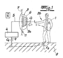
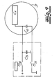
- Fig. 1 is a keyless actuation and / or Locking device shown in its basic structure.
- This user-specific Disk 1 is from a motor vehicle Control unit 2 on the access authorization queried the person in question 3b.
- a bidirectional data exchange or dialog is running by electromagnetic means (i.e. wireless) between the user-specific data carrier 1 and the motor vehicle side Control unit 2 from. It is well known (cf. EP 0 218 251 B1 by way of example only) and not Subject of the present invention.
- a Trigger signal generator provided, which essentially has a capacitive sensor 3.
- This capacitive working sensor 3 has two electrodes, namely a sensor electrode or conductivity electrode 3a on the one hand and a hand or another of the conductivity electrode 3a approaching part 3b of the human Body or person 3b on the other hand. In this part 3b it is within the scope of the embodiment outstretched hand 3b of the operator concerned.
- the evaluation unit 4 is connected via a feed line 5 to the conductivity electrode 3a, which in turn is embedded in a handle or a handle 6.
- an associated motor vehicle 7 can be opened, of which only part of a motor vehicle door 7 is shown.
- a lock that locks the motor vehicle door 7 Prior to this, however, a lock that locks the motor vehicle door 7 must be unlocked, which takes place following the positive data query between the operator-specific data carrier 1 and the motor vehicle-side control unit 2.
- the aforementioned capacitances in the pF range are measured by the evaluation unit 4, which is designed as an electronic (microprocessor) circuit and is capacitively coupled to the ground potential or ground potential 8 within the scope of the exemplary embodiment.
- a connecting line 9 is used for this purpose.
- the operator is also capacitively coupled to the ground or earth potential 8, which is indicated by capacitors C 2 , C 3 indicated in each case in comparison to the capacitor C 1 formed by the electrodes 3 a, 3 b.
- the electrode 3a or conductivity electrode 3a may be as Grid or surface electrode and be designed by the operator have an applied dielectric for insulation. Shields are also conceivable to ensure that those located on the conductivity electrode 3a Loads from the motor vehicle or the motor vehicle door Form 7 away-facing field.
- the trigger signal described only as an example for the introduction of the previously discussed question / answer dialog as part of the access authorization check is used in a motor vehicle. You might as well the trigger signal generator is also easy to operate Light source, for opening a door, unlocking one Lock etc. can be used.
- the changes in capacitance associated with the approach of the hand 3b to the conductivity electrode 3a are determined as variations in the charging time and / or the discharging time of the sensor 3.
- the sensor 3 - in addition to the capacitor C 1 formed from the conductivity electrode 3a and the hand 3b - also has a reference capacitor C 4 (cf. FIGS. 2, 8 and 9).
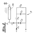
- the (external) parallel capacitor C 5 is charged and discharged at regular intervals. This is ensured by the evaluation unit 4 in connection with an indicated current source, the evaluation unit 4 closing a switch S 1 via a control line, which is an electronic switch, as part of the charging process shown in FIG. 2.
- a control line which is an electronic switch, as part of the charging process shown in FIG. 2.
- two further switches S 2 and S 3 are provided, which are open during the described charging process according to FIG. 2 and are also addressed by the evaluation unit 4 via control lines.
- the charging current flows primarily to the parallel capacitor C 5 and from there back to the ground or to the earth potential 8.
- the reference capacitor C 4 is not charged, so it keeps its charge Q which may be on it.
- the capacitor C 1 is equipped with a capacitance of almost 0, the charging current flows - as stated - mainly to the parallel capacitor C 5 .
- the capacitor C 1 assumes significant values or its capacitance changes from 0 to values in the pF range. Then a (slight) charging current flows on the one hand to the conductivity electrode 3a and on the other hand via the parallel capacitor C 5 back to the ground or to the ground potential 8.
- the charging process begins at a certain level of voltage or charge U, Q and ends after a threshold value U S , Q S has been exceeded.
- This threshold value U S , Q S of the voltage U at the reference capacitor C 4 or charge Q at the reference capacitor C 4 can be specified using the evaluation unit 4.
- the associated charging time T is detected by means of the evaluation unit 4 and then the switch S 2 is opened and the switch S 3 is closed, so that the short circuit caused thereby causes the reference capacitor C 4 discharges.
- a charge / discharge cycle with a duration L can be derived from this.
- the respective charging times T are dimensioned essentially the same and can be averaged, so that a reference time period T ref is available for the evaluation of approximations.
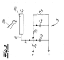
- the reference capacitor C 4 is therefore discharged at regular intervals, essentially in alternation with the charging processes of the parallel capacitor C 5 . This is because the parallel capacitor C 5 is alternately charged and discharged and transfers its charge to the reference capacitor C 4 when it is discharged.
- the reference capacitor C 4 is disconnected during charging of C 5 (and, if appropriate, C 1) of the parallel capacitor C 5, because the switch S is open then. 2
- This switch S 2 like the switches S 1 and S 3, is in each case an electronic transistor switch which, together with the evaluation unit 4 and the capacitors C 4 and C 5 and the conductivity electrode 3a, forms a compact electronic unit which, taken together can even be provided as a circuit.
- the recalibration is carried out at certain predetermined time intervals which are in the range from approx. 100 to 200 msec., In any case under one second.
- the recalibration leads to the increased capacitance C 1 resulting in a reduced recharge time T ref , as shown in FIG. 6 in comparison to the original reference time period T ref old .
- the difference between T ref old and T ref new is measured at ⁇ x.
- the sensitivity of the sensor remains constant and takes into account environmental influences (rain, temperature) in particular.
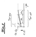
- FIG. 7 compares the charging process taking into account the original charging time T ref old (solid) with the new charging time T ref new (dashed line) and this new charging time T ref new after the calibration of a charging time T when approaching faces a person 3b (dash-dotted). It can be seen that the sensitivity of the sensor 3, which can be determined by the amount .DELTA.t, does not change because only a shift in the reference time period T ref by the amount .DELTA.x has been carried out by the recalibration.
- the evaluation unit 4 and the parallel capacitor C 5 generally form a compact electronics unit.
- this is a microcomputer in which the parallel capacitor C 5 is integrated (cf. the dash-dotted representation in FIGS. 8 and 9).
- the switches S 1, S 2 and S 3 with the associated control lines can also be inserted in this microcomputer in the same way, so that only the conductivity electrode 3a and the reference capacitor C 4 remain as external components.
- switches S 4 to S 7 with associated control lines in connection with the parallel capacitor C 5 are also integrated in a compact electronic unit. This is indicated by the dash-dotted frame, which summarizes the evaluation unit 4 and the parallel capacitor C 5 . In contrast, only the reference capacitor C 4 and the capacitor C 1 remain.
- the cyclic charging of the parallel capacitor C 5 and its discharging by charge transfer to the reference capacitor C 4 is repeated until the reference capacitor C 4 is charged. This usually has a considerably higher capacitance than the parallel capacitor C 5 . Capacities for the reference capacitor C 4 of approximately 50 ⁇ F have proven to be favorable.
- the state of charge U in accordance with the reference capacitor C 4 can be measured in comparison to the predetermined threshold voltage U S , for example at the point indicated in FIG. 8. Two basic output values can be derived from the measured voltage U gem and the threshold voltage U S. If (6) U gem ⁇ U S . For example, the binary information "1" is generated by the evaluation unit 4 and output for further processing. The "1" represents the charged state of the reference capacitor C 4 . In the event that applies (7) U gem ⁇ U S . the reference capacitor C 4 is not (yet) charged, so that the charging processes described above must be continued. The binary information is "0".
Landscapes
- Engineering & Computer Science (AREA)
- Computer Networks & Wireless Communication (AREA)
- Physics & Mathematics (AREA)
- General Physics & Mathematics (AREA)
- Lock And Its Accessories (AREA)
- Control Of Vehicle Engines Or Engines For Specific Uses (AREA)
- Time Recorders, Dirve Recorders, Access Control (AREA)
- Geophysics And Detection Of Objects (AREA)
Abstract
Description

- Fig. 1
- den erfindungsgemäßen Auslösesignalgeber bei einer schlüssellosen Betätigungs- und/oder Schließeinrichtung an einem Kraftfahrzeug schematisch,
- Fig. 2
- den Auslösesignalgeber beim Aufladevorgang seiner Leitfähigkeitselektrode,
- Fig. 3
- den Gegenstand nach Fig. 2 beim Entladen der Leitfähigkeitselektrode und gleichzeitigen Aufladen des Referenzkondensators,
- Fig. 4
- die Spannung bzw. Ladung am Referenzkondensator gegenüber der Zeit, einmal im ursprünglichen Zustand (durchgezogen) und einmal bei Annäherung einer Hand (strichpunktiert),
- Fig. 5
- den Gegenstand nach Fig. 2 schematisch bei Änderung der Umwelteinflüsse (Regen),
- Fig. 6
- den Prozess der Rekalibrierung am Beispiel der Spannung und Ladung am Referenzkondensator gegenüber der Zeit,
- Fig. 7
- die Ergebnisse nach der Fig. 4, die Rekalibrierung gemäß Fig. 6 und schließlich den Aufladevorgang bei sich annähernder Hand, wobei die ursprüngliche Zeit zum Aufladen des Referenzkondensators durchgezogen dargestellt ist, der rekalibrierte Zeitverlauf gestrichelt und schließlich der rekalibrierte Zeitverlauf bei Annäherung der Hand strichpunktiert,
- Fig. 8
- eine abgewandelte Ausgestaltung des Auslösesignalgebers entsprechend den Fig. 2 und 3 und
- Fig. 9
- den Gegenstand nach Fig. 8, reduziert auf seine wesentlichen Bestandteile.
Claims (10)
- Auslösesignalgeber, beispielsweise zur Einleitung eines Frage-/Antwort-Dialogs im Rahmen einer Zugangsberechtigungsprüfung bei einem Kraftfahrzeug (7), mit einem kapazitiv arbeitenden Sensor (3), und mit einer Auswerteeinheit (4), wobei der Sensor (3) Annäherungen und/oder Berührungen beispielsweise einer Person (3b) als zugehörige Kapazitätsänderungen erfasst und an die Auswerteeinheit (4) weiterleitet, dadurch gekennzeichnet, dass die Kapazitätsänderungen als Variationen der Aufladezeit (T) und/oder Entladezeit des Sensors (3) ermittelt werden.
- Auslösesignalgeber nach Anspruch 1, dadurch gekennzeichnet, dass der Sensor (3) eine Leitfähigkeitselektrode (3a) aufweist, die auf Annäherung/Berührungen der Person (3b) im Sinne einer Kapazitätsänderung des aus der Leitfähigkeitselektrode (3a) und der Person (3b) gebildeten Kondensators (C1) reagiert.
- Auslösesignalgeber nach Anspruch 1 oder 2, dadurch gekennzeichnet, dass der Sensor (3) wenigstens einen Referenzkondensator (C4) aufweist, welcher turnusmäßig aufgeladen wird, wobei die Aufladezeit (T) mit Hilfe der Auswerteeinheit (4) bestimmt wird und als Referenzzeitspanne (Tref) für die Auswertung von Annäherungen der Person (3b) zur Verfügung steht.
- Auslösesignalgeber nach einem der Ansprüche 1 bis 3, dadurch gekennzeichnet, dass der Referenzkondensator (C4) turnusmäßig entladen wird.
- Auslösesignalgeber nach einem der Ansprüche 1 bis 4, dadurch gekennzeichnet, dass ein Parallelkondensator (C5) turnusmäßig geladen und entladen wird und seine Ladung beim Entladen an den Referenzkondensator (C4) sowie gegebenenfalls an den aus der Person (3b) sowie der Leitfähigkeitselektrode (3a) gebildeten Kondensator (C1) abgibt.
- Auslösesignalgeber nach Anspruch 5, dadurch gekennzeichnet, dass der Referenzkondensator (C4)(inklusive des Kondensators C1) während des Ladevorganges des Parallelkondensators (C5) von einer zugehörigen Spannungsquelle abgekoppelt ist.
- Auslösesignalgeber nach einem der Ansprüche 1 bis 6, dadurch gekennzeichnet, dass die Aufladezeit (T) des Referenzkondensators (C4) (inklusive gegebenenfalls der Aufladezeit des Kondensators C1), als Zeitraum bis zum Erreichen eines bestimmten Schwellwertes (US, QS) der Ladung (Q) bzw. der Spannung (U) des Referenzkondensators (C4) (inklusive des Kondensators C1) ermittelt wird.
- Auslösesignalgeber nach einem der Ansprüche 1 bis 7, dadurch gekennzeichnet, dass die ermittelten Aufladezeiten (T) mit der Referenzzeitspanne (Tref) verglichen und bei Überschreiten eines vorgegebenen Differenzwertes (Δt) als Annäherung/Berührung des Sensors (3) durch die Person (3b) interpretiert werden.
- Auslösesignalgeber nach einem der Ansprüche 1 bis 8, dadurch gekennzeichnet, dass durch Umwelteinflüsse bedingte Kapazitätsänderungen des Sensors (3) erfasst werden und eine Rekalibrierung der Referenzzeitspanne (Tref neu) nach sich ziehen.
- Auslösesignalgeber nach einem der Ansprüche 1 bis 9, dadurch gekennzeichnet, dass die Rekalibrierung in bestimmten vorgegebenen Zeitspannen, z. B. alle 100 bis 200 msec., vorgenommen wird.
Applications Claiming Priority (4)
| Application Number | Priority Date | Filing Date | Title |
|---|---|---|---|
| DE10207167 | 2002-02-20 | ||
| DE10207167 | 2002-02-20 | ||
| DE10215591.7A DE10215591B4 (de) | 2002-02-20 | 2002-04-10 | Auslösesignalgeber |
| DE10215591 | 2002-04-10 |
Publications (2)
| Publication Number | Publication Date |
|---|---|
| EP1339025A1 true EP1339025A1 (de) | 2003-08-27 |
| EP1339025B1 EP1339025B1 (de) | 2007-01-03 |
Family
ID=27664559
Family Applications (1)
| Application Number | Title | Priority Date | Filing Date |
|---|---|---|---|
| EP03003730A Expired - Lifetime EP1339025B1 (de) | 2002-02-20 | 2003-02-19 | Kraftfahrzeug mit Auslösesignalgeber |
Country Status (3)
| Country | Link |
|---|---|
| EP (1) | EP1339025B1 (de) |
| AT (1) | ATE350730T1 (de) |
| DE (1) | DE50306147D1 (de) |
Cited By (20)
| Publication number | Priority date | Publication date | Assignee | Title |
|---|---|---|---|---|
| WO2005108175A1 (de) * | 2004-04-30 | 2005-11-17 | Huf Hülsbeck & Fürst Gmbh & Co. Kg | Vorrichtung zum betätigen von elektrischen oder elektromechanischen zugangs- bzw zugriffsystemen an oder in einem fahrzeug |
| EP1619633A3 (de) * | 2004-07-22 | 2006-06-14 | Hella KGaA Hueck & Co. | Verfahren zum Steuern der Entriegelung oder Verriegelung der Türen eines Kraftfahrzeuges |
| EP1686543A1 (de) * | 2005-01-28 | 2006-08-02 | Aisin Seiki Kabushiki Kaisha | Vorrichtung für Kapazitätsdetektion |
| WO2007012613A1 (de) * | 2005-07-26 | 2007-02-01 | Huf Hülsbeck & Fürst Gmbh & Co. Kg | Sensoranordnung für eine kraftfahrzeugschliesseinrichtung und zugehöriges verfahren |
| DE102006053572B3 (de) * | 2006-11-14 | 2008-07-03 | Kiekert Ag | Kapazitiver Sensor, insbesondere für eine Einrichtung zum Einklemmschutz an einem Kraftfahrzeug |
| EP2243906A2 (de) | 2009-04-22 | 2010-10-27 | Huf Hülsbeck & Fürst GmbH & Co. KG | Sensorelektronik in einem Kraftfahrzeugtürgriff |
| EP1583236B1 (de) * | 2004-03-30 | 2012-05-02 | Aisin Seiki Kabushiki Kaisha | Kapazitätsänderungsdetektorvorrichtung |
| CN102539935A (zh) * | 2010-10-14 | 2012-07-04 | E.G.O.电气设备制造股份有限公司 | 确定容性传感器元件中电容和/或电容变化的方法和装置 |
| DE102011053314A1 (de) | 2011-09-06 | 2013-03-07 | Huf Hülsbeck & Fürst Gmbh & Co. Kg | Kapazitive Sensoranordnung |
| DE102012100960A1 (de) * | 2012-02-06 | 2013-08-08 | Huf Hülsbeck & Fürst Gmbh & Co. Kg | Verfahren zum Betrieb einer kapazitiven Sensoranordnung an einem Kraftfahrzeug und zugehörige Einrichtung |
| EP2711488A2 (de) | 2012-09-25 | 2014-03-26 | Huf Hülsbeck & Fürst GmbH & Co. KG | Kraftfahrzeugtürgriff mit Sensorelektronik |
| WO2014068008A1 (de) * | 2012-10-30 | 2014-05-08 | Digades Gmbh Digitales Und Analoges Schaltungsdesign | Sensorsystem zur detektion der annäherung von personen und gegenständen, verfahren zum betreiben des sensorsystems sowie dessen verwendung |
| DE102013102469A1 (de) | 2013-03-12 | 2014-10-02 | Huf Hülsbeck & Fürst Gmbh & Co. Kg | Kapazitive Sensoranordnung mit Schirmelektrode |
| CN104137419A (zh) * | 2012-03-21 | 2014-11-05 | 胡夫·许尔斯贝克和福斯特有限及两合公司 | 控制汽车门开启的电容传感器组件及相应操作方法 |
| US9081032B2 (en) | 2010-10-22 | 2015-07-14 | Huf Huelsbeck & Fuerst Gmbh & Co. Kg | Capacitive sensor arrangement for switching a door opening on a motor vehicle |
| DE102015122086A1 (de) | 2015-12-17 | 2017-06-22 | Huf Hülsbeck & Fürst Gmbh & Co. Kg | Fahrzeugtürgriff mit Druckschalter |
| US9829346B2 (en) | 2013-09-12 | 2017-11-28 | Huf Huelsbeck & Fuerst Gmbh & Co. Kg | Operating device for motor vehicles |
| US9945171B2 (en) | 2015-02-11 | 2018-04-17 | Huf Huelsbeck & Fuerst Gmbh & Co. Kg | Sensor assembly for a motor vehicle |
| EP2824002B1 (de) | 2010-11-04 | 2021-05-12 | Huf Hülsbeck & Fürst GmbH & Co. KG | Verfahren zum Öffnen oder Schließen eines Kraftfahrzeugs |
| DE102004048329B4 (de) | 2004-10-05 | 2022-08-11 | Volkswagen Ag | Verfahren zum Betreiben eines Außensensors und entsprechende Vorrichtung |
Families Citing this family (12)
| Publication number | Priority date | Publication date | Assignee | Title |
|---|---|---|---|---|
| DE102009031824A1 (de) | 2009-07-03 | 2011-01-05 | Huf Hülsbeck & Fürst Gmbh & Co. Kg | Kapazitive Sensoranordnung mit einer Sensorelektrode, einer Schirmelektrode und einer Hintergrundelektrode |
| DE102010027508B4 (de) | 2009-07-17 | 2023-12-21 | Huf Hülsbeck & Fürst Gmbh & Co. Kg | Sensoreinrichtung sowie Moduleinheit dafür |
| DE102009059202A1 (de) | 2009-07-20 | 2011-02-03 | Huf Hülsbeck & Fürst Gmbh & Co. Kg | Sensormodul |
| DE102010002559B4 (de) | 2010-03-03 | 2025-08-14 | Huf Hülsbeck & Fürst Gmbh & Co. Kg | Kapazitive Sensorvorrichtung zur Schaltung einer Türöffnung an einem Kraftfahrzeug und Stoßfänger damit |
| DE102011053897A1 (de) | 2011-09-23 | 2013-03-28 | Huf Hülsbeck & Fürst Gmbh & Co. Kg | Sensoranordnung zur Annäherungserkennung an einem Kraftfahrzeug |
| DE102012102060A1 (de) | 2012-03-12 | 2013-09-12 | Huf Hülsbeck & Fürst Gmbh & Co. Kg | Kapazitive Sensoranordnung an einem Kraftfahrzeug zur Erfassung von Bewegungsgesten |
| DE102012104915A1 (de) | 2012-06-06 | 2013-12-12 | Huf Hülsbeck & Fürst Gmbh & Co. Kg | Kapazitive Sensoranordnung zur Schaltung einer Türöffnung an einem Kraftfahrzeug |
| DE102012104916A1 (de) | 2012-06-06 | 2013-12-12 | Huf Hülsbeck & Fürst Gmbh & Co. Kg | Kapazitive Sensoranordnung zur Schaltung einer Türöffnung an einem Kraftfahrzeug |
| DE102012105363A1 (de) | 2012-06-20 | 2013-12-24 | Huf Hülsbeck & Fürst Gmbh & Co. Kg | Sensoranordnung zur Betätigungserfassung an einem Kraftfahrzeug |
| DE102012110436A1 (de) | 2012-10-31 | 2014-04-30 | Huf Hülsbeck & Fürst Gmbh & Co. Kg | Elektronische Sensoreinheit zur Erfassung einer berührungslosen Betätigung einer Tür oder Klappe an einem Kraftfahrzeug |
| DE102013105539A1 (de) | 2013-05-29 | 2014-12-04 | Huf Hülsbeck & Fürst Gmbh & Co. Kg | Elektronische Sensoreinheit zur Erfassung einer berührungslosen Betätigung einer Tür oder Klappe an einem Kraftfahrzeug |
| EP3057234B1 (de) | 2015-02-11 | 2018-11-21 | Huf Hülsbeck & Fürst GmbH & Co. KG | Sensoranordnung für ein kraftfahrzeug |
Citations (3)
| Publication number | Priority date | Publication date | Assignee | Title |
|---|---|---|---|---|
| DE19701899A1 (de) * | 1996-01-21 | 1997-10-30 | Ifm Electronic Gmbh | Schaltungsanordnung zur Erfassung der Kapazität bzw. einer Kapazitätsänderung eines kapazitiven Schaltungs- oder Bauelementes |
| DE19620059A1 (de) * | 1996-05-20 | 1997-11-27 | Ifm Electronic Gmbh | Schaltungsanordnung zum Entriegeln mindestens eines Türschlosses eines Kraftfahrzeugs |
| US5730165A (en) * | 1995-12-26 | 1998-03-24 | Philipp; Harald | Time domain capacitive field detector |
-
2003
- 2003-02-19 EP EP03003730A patent/EP1339025B1/de not_active Expired - Lifetime
- 2003-02-19 AT AT03003730T patent/ATE350730T1/de not_active IP Right Cessation
- 2003-02-19 DE DE50306147T patent/DE50306147D1/de not_active Expired - Lifetime
Patent Citations (3)
| Publication number | Priority date | Publication date | Assignee | Title |
|---|---|---|---|---|
| US5730165A (en) * | 1995-12-26 | 1998-03-24 | Philipp; Harald | Time domain capacitive field detector |
| DE19701899A1 (de) * | 1996-01-21 | 1997-10-30 | Ifm Electronic Gmbh | Schaltungsanordnung zur Erfassung der Kapazität bzw. einer Kapazitätsänderung eines kapazitiven Schaltungs- oder Bauelementes |
| DE19620059A1 (de) * | 1996-05-20 | 1997-11-27 | Ifm Electronic Gmbh | Schaltungsanordnung zum Entriegeln mindestens eines Türschlosses eines Kraftfahrzeugs |
Cited By (34)
| Publication number | Priority date | Publication date | Assignee | Title |
|---|---|---|---|---|
| EP1583236B1 (de) * | 2004-03-30 | 2012-05-02 | Aisin Seiki Kabushiki Kaisha | Kapazitätsänderungsdetektorvorrichtung |
| CN100450838C (zh) * | 2004-04-30 | 2009-01-14 | 胡夫休尔斯贝克及福尔斯特公司 | 用于对汽车上或汽车中的电动式或机电式入口系统或进入系统进行操作的装置 |
| WO2005108175A1 (de) * | 2004-04-30 | 2005-11-17 | Huf Hülsbeck & Fürst Gmbh & Co. Kg | Vorrichtung zum betätigen von elektrischen oder elektromechanischen zugangs- bzw zugriffsystemen an oder in einem fahrzeug |
| KR101089854B1 (ko) * | 2004-04-30 | 2011-12-05 | 후프 휠스벡 운트 퓌르스트 게엠베하 운트 콤파니 카게 | 차체 또는 차량 내부에 설치된 전자식 또는 전자기계식접근 시스템을 구동하기 위한 장치 |
| EP1619633A3 (de) * | 2004-07-22 | 2006-06-14 | Hella KGaA Hueck & Co. | Verfahren zum Steuern der Entriegelung oder Verriegelung der Türen eines Kraftfahrzeuges |
| DE102004048329B4 (de) | 2004-10-05 | 2022-08-11 | Volkswagen Ag | Verfahren zum Betreiben eines Außensensors und entsprechende Vorrichtung |
| EP1686543A1 (de) * | 2005-01-28 | 2006-08-02 | Aisin Seiki Kabushiki Kaisha | Vorrichtung für Kapazitätsdetektion |
| US7245131B2 (en) | 2005-01-28 | 2007-07-17 | Aisin Seiki Kabushiki Kaisha | Capacitance detection apparatus |
| WO2007012613A1 (de) * | 2005-07-26 | 2007-02-01 | Huf Hülsbeck & Fürst Gmbh & Co. Kg | Sensoranordnung für eine kraftfahrzeugschliesseinrichtung und zugehöriges verfahren |
| US7654147B2 (en) * | 2005-07-26 | 2010-02-02 | Huf Hulsbeck & Furst Gmbh & C. Kg | Sensor arrangement for a motor-vehicle locking device and an associated method |
| CN101233287B (zh) * | 2005-07-26 | 2011-01-26 | 胡夫·许尔斯贝克和福斯特有限及两合公司 | 机动车锁定装置的传感器设备和相应方法 |
| DE102006053572B3 (de) * | 2006-11-14 | 2008-07-03 | Kiekert Ag | Kapazitiver Sensor, insbesondere für eine Einrichtung zum Einklemmschutz an einem Kraftfahrzeug |
| US8482303B2 (en) | 2009-04-22 | 2013-07-09 | Huf Hulsbeck & Furst Gmbh & Co. Kg | Sensor electronics in a vehicle door handle |
| DE102009002566A1 (de) | 2009-04-22 | 2010-10-28 | Huf Hülsbeck & Fürst Gmbh & Co. Kg | Sensorelektronik in einem Kraftfahrzeugtürgriff |
| EP2243906A2 (de) | 2009-04-22 | 2010-10-27 | Huf Hülsbeck & Fürst GmbH & Co. KG | Sensorelektronik in einem Kraftfahrzeugtürgriff |
| US8854063B2 (en) | 2010-10-14 | 2014-10-07 | E.G.O. Elektro-Gerätebau GmbH | Method and apparatus for determining a capacitance and/or change in capacitance of a capacitive sensor element |
| EP2442447A3 (de) * | 2010-10-14 | 2014-03-05 | E.G.O. Elektro-Gerätebau GmbH | Verfahren und Vorrichtung zum Bestimmen einer Kapazität und/oder einer Kapazitätsänderung eines kapazitiven Sensorelements |
| CN102539935A (zh) * | 2010-10-14 | 2012-07-04 | E.G.O.电气设备制造股份有限公司 | 确定容性传感器元件中电容和/或电容变化的方法和装置 |
| US9081032B2 (en) | 2010-10-22 | 2015-07-14 | Huf Huelsbeck & Fuerst Gmbh & Co. Kg | Capacitive sensor arrangement for switching a door opening on a motor vehicle |
| EP2824002B2 (de) † | 2010-11-04 | 2025-02-19 | Huf Hülsbeck & Fürst GmbH & Co. KG | Verfahren zum Öffnen oder Schließen eines Kraftfahrzeugs |
| EP2824002B1 (de) | 2010-11-04 | 2021-05-12 | Huf Hülsbeck & Fürst GmbH & Co. KG | Verfahren zum Öffnen oder Schließen eines Kraftfahrzeugs |
| EP2568605A1 (de) | 2011-09-06 | 2013-03-13 | Huf Hülsbeck & Fürst GmbH & Co. KG | Kapazitive Sensoranordnung |
| DE102011053314A1 (de) | 2011-09-06 | 2013-03-07 | Huf Hülsbeck & Fürst Gmbh & Co. Kg | Kapazitive Sensoranordnung |
| DE102012100960A1 (de) * | 2012-02-06 | 2013-08-08 | Huf Hülsbeck & Fürst Gmbh & Co. Kg | Verfahren zum Betrieb einer kapazitiven Sensoranordnung an einem Kraftfahrzeug und zugehörige Einrichtung |
| US9464921B2 (en) | 2012-02-06 | 2016-10-11 | Huf Huelsbeck & Fuerst Gmbh & Co. Kg | Method for the operation of a capacitive sensor array on a motor vehicle and associated device |
| CN104137419B (zh) * | 2012-03-21 | 2019-01-11 | 胡夫·许尔斯贝克和福斯特有限及两合公司 | 控制汽车门开启的电容传感器组件及相应操作方法 |
| CN104137419A (zh) * | 2012-03-21 | 2014-11-05 | 胡夫·许尔斯贝克和福斯特有限及两合公司 | 控制汽车门开启的电容传感器组件及相应操作方法 |
| DE102012109034A1 (de) | 2012-09-25 | 2014-03-27 | Huf Hülsbeck & Fürst Gmbh & Co. Kg | Kraftfahrzeugtürgriff mit Sensorelektronik |
| EP2711488A2 (de) | 2012-09-25 | 2014-03-26 | Huf Hülsbeck & Fürst GmbH & Co. KG | Kraftfahrzeugtürgriff mit Sensorelektronik |
| WO2014068008A1 (de) * | 2012-10-30 | 2014-05-08 | Digades Gmbh Digitales Und Analoges Schaltungsdesign | Sensorsystem zur detektion der annäherung von personen und gegenständen, verfahren zum betreiben des sensorsystems sowie dessen verwendung |
| DE102013102469A1 (de) | 2013-03-12 | 2014-10-02 | Huf Hülsbeck & Fürst Gmbh & Co. Kg | Kapazitive Sensoranordnung mit Schirmelektrode |
| US9829346B2 (en) | 2013-09-12 | 2017-11-28 | Huf Huelsbeck & Fuerst Gmbh & Co. Kg | Operating device for motor vehicles |
| US9945171B2 (en) | 2015-02-11 | 2018-04-17 | Huf Huelsbeck & Fuerst Gmbh & Co. Kg | Sensor assembly for a motor vehicle |
| DE102015122086A1 (de) | 2015-12-17 | 2017-06-22 | Huf Hülsbeck & Fürst Gmbh & Co. Kg | Fahrzeugtürgriff mit Druckschalter |
Also Published As
| Publication number | Publication date |
|---|---|
| DE50306147D1 (de) | 2007-02-15 |
| EP1339025B1 (de) | 2007-01-03 |
| ATE350730T1 (de) | 2007-01-15 |
Similar Documents
| Publication | Publication Date | Title |
|---|---|---|
| EP1339025A1 (de) | Auslösesignalgeber | |
| EP1505734B1 (de) | Kapazitiver Näherungsschalter | |
| EP1235190B1 (de) | Schlüssellose Betätigungs und/oder Schliesseinrichtung | |
| EP2795798B1 (de) | Einrichtung und verfahren zur auswertung der kapazität einer sensorelektrode eines annäherungssensors | |
| DE102011010620B4 (de) | Verfahren zum Messen einer Kapazität | |
| EP1910631B1 (de) | Sensoranordnung für eine kraftfahrzeugschliesseinrichtung und zugehöriges verfahren | |
| EP1341306B1 (de) | Elektrische Schaltung für ein kapazitives Sensorelement | |
| EP1450489B1 (de) | Auslösesignalgeber | |
| DE102012105266B4 (de) | Kapazitiver Annäherungssensor für ein Kraftfahrzeug | |
| EP2828973B1 (de) | Kapazitive sensoranordnung zur schaltung einer türöffnung an einem kraftfahrzeug und zugehöriges verfahren | |
| DE4242230A1 (de) | Sensoreinrichtung zum Erkennen eines seitlichen Aufpralles auf ein Kraftfahrzeug | |
| EP3829065A1 (de) | Kapazitive sensoreinrichtung sowie verfahren zur erkennung einer objektannäherung | |
| EP1103432A1 (de) | Kraftfahrzeug-Türschliesssystem | |
| WO2000018012A1 (de) | Totmannschaltung | |
| EP0820391B1 (de) | Anordnung zur auslösung einer personenschutzanlage | |
| DE102006029120A1 (de) | Schaltungsanordnung zur Erfassung der Kapazität bzw. einer Kapazitätsänderung eines kapazitiven Schaltungs- oder Bauelements | |
| DE102008014516A1 (de) | Vorrichtung zum Ver- und Entriegeln einer Fahrzeugtür | |
| DE10215591B4 (de) | Auslösesignalgeber | |
| CH700376A2 (de) | Kapazitiver Sensor und Verfahren zur kapazitiven Erfassung eines Objektabstandes. | |
| EP1966892A1 (de) | Sensoranordnung zum erfassen des andrückens eines bedienkörperteils an eine sensorfläche | |
| EP1770653B1 (de) | Auslöseeinrichtung für Kraftfahrzeuge | |
| EP2943630B1 (de) | Kapazitive annäherungssensoranordnung an einer tür eines kraftfahrzeugs zum erfassen einer näherungsweise horizontalen annäherungsbewegung einer bedienerhand | |
| DE10339753B4 (de) | Verfahren zum Messen einer physikalischen Größe und Schaltungsanordnung zur Erfassung der Kapazität bzw. einer Kapazitätsänderung eines kapazitiven Schaltungs- oder Bauelements | |
| DE10108354A1 (de) | Schlüssellose Betätigungs- und/oder Schließeinrichtung | |
| EP3620802A1 (de) | Anordnung für eine detektion bei einem türgriff eines fahrzeuges |
Legal Events
| Date | Code | Title | Description |
|---|---|---|---|
| PUAI | Public reference made under article 153(3) epc to a published international application that has entered the european phase |
Free format text: ORIGINAL CODE: 0009012 |
|
| AK | Designated contracting states |
Designated state(s): AT BE BG CH CY CZ DE DK EE ES FI FR GB GR HU IE IT LI LU MC NL PT SE SI SK TR |
|
| AX | Request for extension of the european patent |
Extension state: AL LT LV MK RO |
|
| 17P | Request for examination filed |
Effective date: 20040219 |
|
| AKX | Designation fees paid |
Designated state(s): AT BE BG CH CY CZ DE DK EE ES FI FR GB GR HU IE IT LI LU MC NL PT SE SI SK TR |
|
| 17Q | First examination report despatched |
Effective date: 20041019 |
|
| GRAP | Despatch of communication of intention to grant a patent |
Free format text: ORIGINAL CODE: EPIDOSNIGR1 |
|
| RTI1 | Title (correction) |
Free format text: VEHICLE WITH RELEASE TRIGGER |
|
| GRAS | Grant fee paid |
Free format text: ORIGINAL CODE: EPIDOSNIGR3 |
|
| GRAA | (expected) grant |
Free format text: ORIGINAL CODE: 0009210 |
|
| AK | Designated contracting states |
Kind code of ref document: B1 Designated state(s): AT BE BG CH CY CZ DE DK EE ES FI FR GB GR HU IE IT LI LU MC NL PT SE SI SK TR |
|
| PG25 | Lapsed in a contracting state [announced via postgrant information from national office to epo] |
Ref country code: IE Free format text: LAPSE BECAUSE OF FAILURE TO SUBMIT A TRANSLATION OF THE DESCRIPTION OR TO PAY THE FEE WITHIN THE PRESCRIBED TIME-LIMIT Effective date: 20070103 Ref country code: FI Free format text: LAPSE BECAUSE OF FAILURE TO SUBMIT A TRANSLATION OF THE DESCRIPTION OR TO PAY THE FEE WITHIN THE PRESCRIBED TIME-LIMIT Effective date: 20070103 Ref country code: NL Free format text: LAPSE BECAUSE OF FAILURE TO SUBMIT A TRANSLATION OF THE DESCRIPTION OR TO PAY THE FEE WITHIN THE PRESCRIBED TIME-LIMIT Effective date: 20070103 Ref country code: DK Free format text: LAPSE BECAUSE OF FAILURE TO SUBMIT A TRANSLATION OF THE DESCRIPTION OR TO PAY THE FEE WITHIN THE PRESCRIBED TIME-LIMIT Effective date: 20070103 Ref country code: SI Free format text: LAPSE BECAUSE OF FAILURE TO SUBMIT A TRANSLATION OF THE DESCRIPTION OR TO PAY THE FEE WITHIN THE PRESCRIBED TIME-LIMIT Effective date: 20070103 |
|
| REG | Reference to a national code |
Ref country code: GB Ref legal event code: FG4D Free format text: NOT ENGLISH |
|
| REF | Corresponds to: |
Ref document number: 50306147 Country of ref document: DE Date of ref document: 20070215 Kind code of ref document: P |
|
| REG | Reference to a national code |
Ref country code: IE Ref legal event code: FG4D Free format text: LANGUAGE OF EP DOCUMENT: GERMAN |
|
| PG25 | Lapsed in a contracting state [announced via postgrant information from national office to epo] |
Ref country code: LI Free format text: LAPSE BECAUSE OF NON-PAYMENT OF DUE FEES Effective date: 20070228 Ref country code: MC Free format text: LAPSE BECAUSE OF NON-PAYMENT OF DUE FEES Effective date: 20070228 Ref country code: CH Free format text: LAPSE BECAUSE OF NON-PAYMENT OF DUE FEES Effective date: 20070228 |
|
| PG25 | Lapsed in a contracting state [announced via postgrant information from national office to epo] |
Ref country code: SE Free format text: LAPSE BECAUSE OF FAILURE TO SUBMIT A TRANSLATION OF THE DESCRIPTION OR TO PAY THE FEE WITHIN THE PRESCRIBED TIME-LIMIT Effective date: 20070403 |
|
| PG25 | Lapsed in a contracting state [announced via postgrant information from national office to epo] |
Ref country code: BG Free format text: LAPSE BECAUSE OF EXPIRATION OF PROTECTION Effective date: 20070404 |
|
| PG25 | Lapsed in a contracting state [announced via postgrant information from national office to epo] |
Ref country code: ES Free format text: LAPSE BECAUSE OF FAILURE TO SUBMIT A TRANSLATION OF THE DESCRIPTION OR TO PAY THE FEE WITHIN THE PRESCRIBED TIME-LIMIT Effective date: 20070414 |
|
| PG25 | Lapsed in a contracting state [announced via postgrant information from national office to epo] |
Ref country code: PT Free format text: LAPSE BECAUSE OF FAILURE TO SUBMIT A TRANSLATION OF THE DESCRIPTION OR TO PAY THE FEE WITHIN THE PRESCRIBED TIME-LIMIT Effective date: 20070604 |
|
| NLV1 | Nl: lapsed or annulled due to failure to fulfill the requirements of art. 29p and 29m of the patents act | ||
| ET | Fr: translation filed | ||
| GBV | Gb: ep patent (uk) treated as always having been void in accordance with gb section 77(7)/1977 [no translation filed] |
Effective date: 20070103 |
|
| REG | Reference to a national code |
Ref country code: IE Ref legal event code: FD4D |
|
| PLBI | Opposition filed |
Free format text: ORIGINAL CODE: 0009260 |
|
| REG | Reference to a national code |
Ref country code: CH Ref legal event code: PL |
|
| PLAX | Notice of opposition and request to file observation + time limit sent |
Free format text: ORIGINAL CODE: EPIDOSNOBS2 |
|
| 26 | Opposition filed |
Opponent name: IFM ELECTRONIC GMBH Effective date: 20071004 |
|
| PG25 | Lapsed in a contracting state [announced via postgrant information from national office to epo] |
Ref country code: SK Free format text: LAPSE BECAUSE OF FAILURE TO SUBMIT A TRANSLATION OF THE DESCRIPTION OR TO PAY THE FEE WITHIN THE PRESCRIBED TIME-LIMIT Effective date: 20070103 Ref country code: GB Free format text: LAPSE BECAUSE OF FAILURE TO SUBMIT A TRANSLATION OF THE DESCRIPTION OR TO PAY THE FEE WITHIN THE PRESCRIBED TIME-LIMIT Effective date: 20070103 |
|
| BERE | Be: lapsed |
Owner name: KIEKERT A.G. Effective date: 20070228 |
|
| PG25 | Lapsed in a contracting state [announced via postgrant information from national office to epo] |
Ref country code: CZ Free format text: LAPSE BECAUSE OF FAILURE TO SUBMIT A TRANSLATION OF THE DESCRIPTION OR TO PAY THE FEE WITHIN THE PRESCRIBED TIME-LIMIT Effective date: 20070103 Ref country code: BE Free format text: LAPSE BECAUSE OF NON-PAYMENT OF DUE FEES Effective date: 20070228 |
|
| PLBB | Reply of patent proprietor to notice(s) of opposition received |
Free format text: ORIGINAL CODE: EPIDOSNOBS3 |
|
| PG25 | Lapsed in a contracting state [announced via postgrant information from national office to epo] |
Ref country code: IT Free format text: LAPSE BECAUSE OF FAILURE TO SUBMIT A TRANSLATION OF THE DESCRIPTION OR TO PAY THE FEE WITHIN THE PRESCRIBED TIME-LIMIT Effective date: 20070103 Ref country code: GR Free format text: LAPSE BECAUSE OF FAILURE TO SUBMIT A TRANSLATION OF THE DESCRIPTION OR TO PAY THE FEE WITHIN THE PRESCRIBED TIME-LIMIT Effective date: 20070404 |
|
| PG25 | Lapsed in a contracting state [announced via postgrant information from national office to epo] |
Ref country code: AT Free format text: LAPSE BECAUSE OF NON-PAYMENT OF DUE FEES Effective date: 20070219 |
|
| PLBP | Opposition withdrawn |
Free format text: ORIGINAL CODE: 0009264 |
|
| PLBD | Termination of opposition procedure: decision despatched |
Free format text: ORIGINAL CODE: EPIDOSNOPC1 |
|
| RAP2 | Party data changed (patent owner data changed or rights of a patent transferred) |
Owner name: HUF ELECTRONICS GMBH |
|
| PLAB | Opposition data, opponent's data or that of the opponent's representative modified |
Free format text: ORIGINAL CODE: 0009299OPPO |
|
| PG25 | Lapsed in a contracting state [announced via postgrant information from national office to epo] |
Ref country code: EE Free format text: LAPSE BECAUSE OF FAILURE TO SUBMIT A TRANSLATION OF THE DESCRIPTION OR TO PAY THE FEE WITHIN THE PRESCRIBED TIME-LIMIT Effective date: 20070103 |
|
| PLBM | Termination of opposition procedure: date of legal effect published |
Free format text: ORIGINAL CODE: 0009276 |
|
| STAA | Information on the status of an ep patent application or granted ep patent |
Free format text: STATUS: OPPOSITION PROCEDURE CLOSED |
|
| 27C | Opposition proceedings terminated |
Effective date: 20080921 |
|
| PG25 | Lapsed in a contracting state [announced via postgrant information from national office to epo] |
Ref country code: CY Free format text: LAPSE BECAUSE OF FAILURE TO SUBMIT A TRANSLATION OF THE DESCRIPTION OR TO PAY THE FEE WITHIN THE PRESCRIBED TIME-LIMIT Effective date: 20070103 |
|
| PG25 | Lapsed in a contracting state [announced via postgrant information from national office to epo] |
Ref country code: LU Free format text: LAPSE BECAUSE OF NON-PAYMENT OF DUE FEES Effective date: 20070219 |
|
| PG25 | Lapsed in a contracting state [announced via postgrant information from national office to epo] |
Ref country code: TR Free format text: LAPSE BECAUSE OF FAILURE TO SUBMIT A TRANSLATION OF THE DESCRIPTION OR TO PAY THE FEE WITHIN THE PRESCRIBED TIME-LIMIT Effective date: 20070103 Ref country code: HU Free format text: LAPSE BECAUSE OF FAILURE TO SUBMIT A TRANSLATION OF THE DESCRIPTION OR TO PAY THE FEE WITHIN THE PRESCRIBED TIME-LIMIT Effective date: 20070704 |
|
| REG | Reference to a national code |
Ref country code: FR Ref legal event code: TP |
|
| REG | Reference to a national code |
Ref country code: FR Ref legal event code: TP |
|
| PGFP | Annual fee paid to national office [announced via postgrant information from national office to epo] |
Ref country code: FR Payment date: 20110107 Year of fee payment: 9 |
|
| REG | Reference to a national code |
Ref country code: FR Ref legal event code: ST Effective date: 20121031 |
|
| PG25 | Lapsed in a contracting state [announced via postgrant information from national office to epo] |
Ref country code: FR Free format text: LAPSE BECAUSE OF NON-PAYMENT OF DUE FEES Effective date: 20120229 |
|
| PGFP | Annual fee paid to national office [announced via postgrant information from national office to epo] |
Ref country code: DE Payment date: 20210223 Year of fee payment: 19 |
|
| REG | Reference to a national code |
Ref country code: DE Ref legal event code: R119 Ref document number: 50306147 Country of ref document: DE |
|
| PG25 | Lapsed in a contracting state [announced via postgrant information from national office to epo] |
Ref country code: DE Free format text: LAPSE BECAUSE OF NON-PAYMENT OF DUE FEES Effective date: 20220901 |