EP1342658A1 - Bicycle rear derailleur - Google Patents
Bicycle rear derailleur Download PDFInfo
- Publication number
- EP1342658A1 EP1342658A1 EP03005131A EP03005131A EP1342658A1 EP 1342658 A1 EP1342658 A1 EP 1342658A1 EP 03005131 A EP03005131 A EP 03005131A EP 03005131 A EP03005131 A EP 03005131A EP 1342658 A1 EP1342658 A1 EP 1342658A1
- Authority
- EP
- European Patent Office
- Prior art keywords
- side wall
- base member
- derailleur according
- projection
- laterally
- Prior art date
- Legal status (The legal status is an assumption and is not a legal conclusion. Google has not performed a legal analysis and makes no representation as to the accuracy of the status listed.)
- Granted
Links
- 230000008878 coupling Effects 0.000 claims description 10
- 238000010168 coupling process Methods 0.000 claims description 10
- 238000005859 coupling reaction Methods 0.000 claims description 10
- 210000005069 ears Anatomy 0.000 claims description 8
- 238000009434 installation Methods 0.000 description 4
- 230000004048 modification Effects 0.000 description 1
- 238000012986 modification Methods 0.000 description 1
- 230000002093 peripheral effect Effects 0.000 description 1
- 230000004044 response Effects 0.000 description 1
Images




Classifications
-
- B—PERFORMING OPERATIONS; TRANSPORTING
- B62—LAND VEHICLES FOR TRAVELLING OTHERWISE THAN ON RAILS
- B62M—RIDER PROPULSION OF WHEELED VEHICLES OR SLEDGES; POWERED PROPULSION OF SLEDGES OR SINGLE-TRACK CYCLES; TRANSMISSIONS SPECIALLY ADAPTED FOR SUCH VEHICLES
- B62M9/00—Transmissions characterised by use of an endless chain, belt, or the like
- B62M9/04—Transmissions characterised by use of an endless chain, belt, or the like of changeable ratio
- B62M9/06—Transmissions characterised by use of an endless chain, belt, or the like of changeable ratio using a single chain, belt, or the like
- B62M9/10—Transmissions characterised by use of an endless chain, belt, or the like of changeable ratio using a single chain, belt, or the like involving different-sized wheels, e.g. rear sprocket chain wheels selectively engaged by the chain, belt, or the like
- B62M9/12—Transmissions characterised by use of an endless chain, belt, or the like of changeable ratio using a single chain, belt, or the like involving different-sized wheels, e.g. rear sprocket chain wheels selectively engaged by the chain, belt, or the like the chain, belt, or the like being laterally shiftable, e.g. using a rear derailleur
- B62M9/121—Rear derailleurs
- B62M9/125—Mounting the derailleur on the frame
-
- B—PERFORMING OPERATIONS; TRANSPORTING
- B62—LAND VEHICLES FOR TRAVELLING OTHERWISE THAN ON RAILS
- B62M—RIDER PROPULSION OF WHEELED VEHICLES OR SLEDGES; POWERED PROPULSION OF SLEDGES OR SINGLE-TRACK CYCLES; TRANSMISSIONS SPECIALLY ADAPTED FOR SUCH VEHICLES
- B62M9/00—Transmissions characterised by use of an endless chain, belt, or the like
- B62M9/04—Transmissions characterised by use of an endless chain, belt, or the like of changeable ratio
- B62M9/06—Transmissions characterised by use of an endless chain, belt, or the like of changeable ratio using a single chain, belt, or the like
- B62M9/10—Transmissions characterised by use of an endless chain, belt, or the like of changeable ratio using a single chain, belt, or the like involving different-sized wheels, e.g. rear sprocket chain wheels selectively engaged by the chain, belt, or the like
- B62M9/12—Transmissions characterised by use of an endless chain, belt, or the like of changeable ratio using a single chain, belt, or the like involving different-sized wheels, e.g. rear sprocket chain wheels selectively engaged by the chain, belt, or the like the chain, belt, or the like being laterally shiftable, e.g. using a rear derailleur
- B62M9/121—Rear derailleurs
- B62M9/124—Mechanisms for shifting laterally
- B62M9/1242—Mechanisms for shifting laterally characterised by the linkage mechanisms
Definitions
- the present invention is directed to bicycles and, more particularly, to a bicycle rear derailleur.
- Bicycles typically include a frame, front and rear wheels, pedals that are used to rotate one or more front sprockets, a plurality of rear sprockets mounted to the rear wheel, and a chain that engages one of the plurality of front sprockets and one of the plurality of rear sprockets.
- a front derailleur mounted to the frame in close proximity to the plurality of front sprockets is used to shift the chain among the plurality of front sprockets
- a rear derailleur mounted to the frame in close proximity to the plurality of rear sprockets is used to shift the chain among the plurality of rear sprockets.
- the rider typically uses manual, electric, or hydraulic control devices to control the front and rear derailleur.
- a derailleur includes a base member for attachment to a bicycle frame and a movable member supporting a chain guide such that the chain guide moves laterally to shift a chain among a plurality of gears.
- the base member has a laterally inner surface and a laterally outer surface, and it includes a projection extending laterally outwardly for engaging a corresponding recess in the frame. With this arrangement, the base member can be mounted to a laterally inner surface of the frame such that the projection engages a corresponding recess in the frame.
- the laterally inner mounting of the base member helps to minimize the lateral extent of the derailleur so as not to interfere with the folding of the frame, and the projection helps to securely position the derailleur on the frame without requiring additional positioning structures that would increase the overall size of the derailleur.
- a derailleur is adapted to be used with a frame member of a bicycle, wherein the frame member has an axle opening for receiving an axle therethrough and first and second prongs with corresponding first and second end faces, wherein the first and second prongs define a slot in close proximity to the axle opening and an opening extending through the first and second end faces.
- the derailleur comprises a base member and a movable member.
- the base member has a projection dimensioned and positioned to fit into the slot in the frame member such that, when the derailleur is mounted to the frame member, the slot opens through the first and second end faces toward the base member.
- a movable member supports a chain guide and is operatively coupled to the base member such that the chain guide moves laterally to shift a chain among a plurality of gears.
- Fig. 1 is a side view of a folding bicycle 10 that includes a frame 14 with a known folding joint 18 in the middle, a seat 12, a front wheel 22 mounted to a fork 26 that is rotatably mounted in a head tube 30 of frame 14, a handlebar assembly 34 for rotating the fork 26 and front wheel 22, a rear wheel 38 mounted to the rear of frame 14, a pedal assembly 42 rotatably mounted to frame 14 for rotating a front sprocket 46, a plurality of rear sprockets 50 mounted to the rear wheel 38, and a chain 54 that engages the front sprocket 46 and one of the plurality of rear sprockets 50.
- a rear derailleur 58 is mounted to the frame 14 in close proximity to the plurality of rear sprockets 50 for shifting the chain 54 among the plurality of rear sprockets 50.
- a conventional manually operated shift control device 62 mounted to the handlebar assembly 34 controls rear derailleur 58 in a well-known manner.
- multiple front sprockets 46 may be provided, and a front derailleur may be used to shift chain 54 among such a plurality of sprockets.
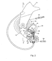
- Fig. 2 is a more detailed view of derailleur 58 mounted to frame 14.
- Derailleur 58 includes a one-piece base member 70, a movable member 74 supporting a chain guide 78, and a link 82 directly connected between opposed coupling ears 84 on base member 70 and between opposed coupling ears 85 on movable member 74 through pivot pins 86 and 90, respectively.
- Movable member 74, and thereby chain guide 78 move laterally to shift chain 54 among the plurality of sprockets 50 in response to the operation of shift control device 62 in a well known manner.
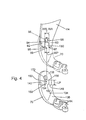
- Fig. 3 is a view taken along line III-III in Fig. 2
- Fig. 4 is a view illustrating the installation of base member 70 on frame 14.
- frame 14 includes a laterally inner surface 64, a laterally outer surface 66, and first and second prongs 92 and 93.
- First and second prongs 92 and 93 have corresponding first and second end faces 95 and 97, wherein first and second prongs 92 and 93 define a recess such as a slot 94 that is contiguous with an axle opening 96 and with an opening 99 that extends through first and second end faces 95 and 97.
- Axle opening 96 receives an axle 98 of rear wheel 38 therein.
- Axle 98 is a conventional quick-release axle comprising a hollow axle portion 102, a draw bar 106 having a threaded end portion 110, a threaded nut 114 screwed onto the threaded end portion 110, and a spring 118 disposed between nut 114 and frame 14.
- Element 122 is a hub locking nut that retains hollow axle portion 102 and other internal components to rear wheel 38.
- Base member 70 has a laterally inner surface 130 and a laterally outer surface 134 that faces laterally inner surface 64 of frame 14 when derailleur 58 is mounted to frame 14.
- Laterally outer surface 134 includes an outermost surface portion 136, a substantially flat and straight recessed surface portion 138, and substantially flat and straight stepped surface portions 142 and 146 extending between outermost surface portion 136 and recessed surface portion 138, wherein stepped surface portions 142 and 146 are substantially perpendicular to both outermost surface portion 136 and recessed surface portion 138.
- a projection 150 extends laterally outwardly from recessed surface portion 138 for engaging slot 94 such that slot 94 opens through the first and second end faces 95 and 97 toward the base member.
- base member 70 does not have a corresponding slot that opens in the same direction as slot 94.
- first and second end faces 95 and 97 face stepped surface portions 142 and 146.
- projection 150 extends between end faces 95 and 97, through opening 99 and into slot 94 as shown in Fig. 4.
- stepped portions 142 and 146 or, for that matter, recessed surface portion 138.
- projection 150 has a substantially rectangular shape. More specifically, projection 150 includes an outer projection surface 154 that is level with outermost surface portion 136, a substantially straight and flat first side wall 158 for facing first prong 92, a substantially straight and flat second side wall 162 for facing second prong 93, and a substantially straight and flat third side wall 166 extending between the end edges of first side wall 158 and second side wall 162.
- First side wall 158 is substantially parallel to second side wall 162, and third side wall 166 is substantially perpendicular to both first side wall 158 and second side wall 162.
- First side wall 158, second side wall 162 and third side wall 166 also are substantially perpendicular to recessed surface portion 138.
- first side wall 158 and second side wall 162 are substantially perpendicular to stepped surface portions 142 and 146.
- none of the foregoing surfaces need to be straight, flat, perpendicular, parallel, recessed or flush, and the particular configurations may depend upon the application.
- a width WP of projection 150 between first side wall 158 and second side wall 162 is substantially equal to a width WS of slot 94.
- a width WA of axle opening 96 is substantially equal to width WS of slot 94. This allows hollow axle portion 102 to be inserted through the end of slot 94 to facilitate installation of wheel 38 to frame 14 without excessive play.
- projection 150 has a shape that prevents projection 150 from rotating in slot 94 when viewed in the lateral direction.
- first side wall 158 and second side wall 162 are both elongated so that a length LP of projection 150 is likewise elongated, and in this embodiment length LP is greater than the width WP of projection 150.
- first and second side walls 158 and 162 even by themselves can stabilize base member 70 within slot 94.
- these dimensions are not necessary and may be changed to suit the application.
- Base member 70 includes a fastener opening 170 for receiving a fastener therethrough.
- Hollow axle portion 102 and draw bar 106 function as a fastener in this embodiment.
- Fastener opening 170 is disposed in close proximity to projection 150.
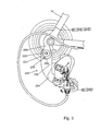
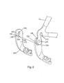
- Figs. 5 and 6 are detailed views of a rear derailleur 200 which represents another embodiment of a derailleur.
- Derailleur 200 is constructed substantially the same as derailleur 58 in the first embodiment, so only the differences will be described in detail.
- derailleur 200 includes a base member 204 that mounts to an extension 208 of frame 14 that extends downwardly from an axle opening 212.
- Extension 208 includes a fastener opening 216 and a recess 224 forming an abutment 228.
- Fastener opening 216 is adapted to receive a fastener 220 therethrough.
- Base member 204 includes a laterally inner surface (not shown), a laterally outer surface 232, and a fastener opening 234 for receiving fastener 220 therethrough.
- a projection 236 extends laterally outwardly from laterally outer surface 232, wherein projection 236 includes an arcuate first side wall 240, and arcuate second side wall 244, a third side wall 248 extending between one edge of first side wall 240 and second side wall 244, and a fourth side wall 252 extending between an opposite edge of first side wall 240 and second side wall 244. Fourth side wall 252 ordinarily abuts against abutment 228 formed by recess 224 when base member 204 is mounted to extension 208. As with the first embodiment, base member 204 is mounted to the laterally inner surface of extension 208.
- fastener 220 comprises a nut and bolt assembly.
- fastener opening 234 in base member 204 and/or fastener opening 216 in extension 208 may have a threaded inner peripheral surface
- fastener 220 may be a bolt that screws into one or both openings, with the bolt head being located either at the inner lateral surface of base member 204 or at the outer lateral surface of extension 208.
- Figs. 7 and 8 are detailed views of a rear derailleur 300 which represents another embodiment.
- Derailleur 300 is constructed substantially the same as derailleur 58 in the first embodiment, so only the differences will be described in detail.
- a base member 70' is constructed the same as base member 70 in the first embodiment, except recessed surface portion 138 and projection 150 are formed on the laterally inner surface 130 of base member 70', and laterally inner surface 130 faces laterally outer surface 66 of frame 14 when derailleur 300 is mounted to frame 14.
- the recess that receives the projection in the base member may be a simple depression or some other receding structure associated with the surface of the frame instead of the cutouts shown, or it may be a combination of such structures.
- Components that are shown directly connected or contacting each other may have intermediate structures disposed between them. The functions of one element may be performed by two, and vice versa. It is not necessary for all advantages to be present in a particular embodiment at the same time.
Landscapes
- Engineering & Computer Science (AREA)
- Chemical & Material Sciences (AREA)
- Combustion & Propulsion (AREA)
- Transportation (AREA)
- Mechanical Engineering (AREA)
- Transmissions By Endless Flexible Members (AREA)
- Motorcycle And Bicycle Frame (AREA)
Abstract
Description
- The present invention is directed to bicycles and, more particularly, to a bicycle rear derailleur.
- Bicycles typically include a frame, front and rear wheels, pedals that are used to rotate one or more front sprockets, a plurality of rear sprockets mounted to the rear wheel, and a chain that engages one of the plurality of front sprockets and one of the plurality of rear sprockets. A front derailleur mounted to the frame in close proximity to the plurality of front sprockets is used to shift the chain among the plurality of front sprockets, and a rear derailleur mounted to the frame in close proximity to the plurality of rear sprockets is used to shift the chain among the plurality of rear sprockets. The rider typically uses manual, electric, or hydraulic control devices to control the front and rear derailleurs.
- Small bicycles that have a frame capable of folding upon itself to facilitate carrying on public transportation or storage at work facilities are becoming more popular. Because such bicycles are carried and stored in crowded places, they should be very compact. Thus, the sizes of the frame and wheels are minimized accordingly. Very often the frame folds in half in the middle so that the front wheel is placed adjacent to the rear wheel. Thus, the rear derailleur should be as compact as possible so as not to protrude excessively laterally and impact the front wheel, thereby preventing compact folding of the frame. Furthermore, the rear derailleur should not be so large or mounted so low on the frame as to strike the ground as the bicycle is being ridden.
- The present invention is directed to various inventive features of a bicycle derailleur. In one embodiment of such inventive features, a derailleur includes a base member for attachment to a bicycle frame and a movable member supporting a chain guide such that the chain guide moves laterally to shift a chain among a plurality of gears. The base member has a laterally inner surface and a laterally outer surface, and it includes a projection extending laterally outwardly for engaging a corresponding recess in the frame. With this arrangement, the base member can be mounted to a laterally inner surface of the frame such that the projection engages a corresponding recess in the frame. The laterally inner mounting of the base member helps to minimize the lateral extent of the derailleur so as not to interfere with the folding of the frame, and the projection helps to securely position the derailleur on the frame without requiring additional positioning structures that would increase the overall size of the derailleur.
- In another embodiment of such inventive features, a derailleur is adapted to be used with a frame member of a bicycle, wherein the frame member has an axle opening for receiving an axle therethrough and first and second prongs with corresponding first and second end faces, wherein the first and second prongs define a slot in close proximity to the axle opening and an opening extending through the first and second end faces. In this embodiment, the derailleur comprises a base member and a movable member. The base member has a projection dimensioned and positioned to fit into the slot in the frame member such that, when the derailleur is mounted to the frame member, the slot opens through the first and second end faces toward the base member. A movable member supports a chain guide and is operatively coupled to the base member such that the chain guide moves laterally to shift a chain among a plurality of gears.
- Additional inventive features will become apparent from the description below, and such features may form the basis of further inventions.
-
- Fig. 1 is a side view of a folding bicycle that includes a particular embodiment of a rear derailleur;
- Fig. 2 is a more detailed view of the derailleur shown in Fig. 1;
- Fig. 3 is a view taken along line III-III in Fig. 2;
- Fig. 4 is a view illustrating the installation of the derailleur base member on the frame;
- Fig. 5 is a detailed view of another embodiment of a rear derailleur;
- Fig. 6 is a view illustrating the installation of the derailleur base member on the frame;
- Fig. 7 illustrates an alternative embodiment of a rear derailleur; and
- Fig. 8 is a view taken along line VIII-VIII in Fig. 7.
- Fig. 1 is a side view of a folding
bicycle 10 that includes aframe 14 with a knownfolding joint 18 in the middle, aseat 12, afront wheel 22 mounted to afork 26 that is rotatably mounted in ahead tube 30 offrame 14, ahandlebar assembly 34 for rotating thefork 26 andfront wheel 22, arear wheel 38 mounted to the rear offrame 14, a pedal assembly 42 rotatably mounted toframe 14 for rotating afront sprocket 46, a plurality ofrear sprockets 50 mounted to therear wheel 38, and achain 54 that engages thefront sprocket 46 and one of the plurality ofrear sprockets 50. Arear derailleur 58 is mounted to theframe 14 in close proximity to the plurality ofrear sprockets 50 for shifting thechain 54 among the plurality ofrear sprockets 50. In this embodiment, a conventional manually operatedshift control device 62 mounted to thehandlebar assembly 34 controlsrear derailleur 58 in a well-known manner. In other embodiments, multiplefront sprockets 46 may be provided, and a front derailleur may be used to shiftchain 54 among such a plurality of sprockets. - Fig. 2 is a more detailed view of
derailleur 58 mounted toframe 14. Derailleur 58 includes a one-piece base member 70, amovable member 74 supporting achain guide 78, and alink 82 directly connected betweenopposed coupling ears 84 onbase member 70 and between opposedcoupling ears 85 onmovable member 74 throughpivot pins Movable member 74, and therebychain guide 78, move laterally to shiftchain 54 among the plurality ofsprockets 50 in response to the operation ofshift control device 62 in a well known manner. - Fig. 3 is a view taken along line III-III in Fig. 2, and Fig. 4 is a view illustrating the installation of
base member 70 onframe 14. In this embodiment,frame 14 includes a laterallyinner surface 64, a laterallyouter surface 66, and first andsecond prongs second prongs second prongs slot 94 that is contiguous with anaxle opening 96 and with an opening 99 that extends through first and second end faces 95 and 97. Axleopening 96 receives anaxle 98 ofrear wheel 38 therein. Axle 98 is a conventional quick-release axle comprising ahollow axle portion 102, adraw bar 106 having a threadedend portion 110, a threadednut 114 screwed onto the threadedend portion 110, and aspring 118 disposed betweennut 114 andframe 14.Element 122 is a hub locking nut that retainshollow axle portion 102 and other internal components torear wheel 38. -
Base member 70 has a laterallyinner surface 130 and a laterallyouter surface 134 that faces laterallyinner surface 64 offrame 14 whenderailleur 58 is mounted toframe 14. Laterallyouter surface 134 includes anoutermost surface portion 136, a substantially flat and straightrecessed surface portion 138, and substantially flat and straightstepped surface portions outermost surface portion 136 andrecessed surface portion 138, wherein steppedsurface portions outermost surface portion 136 andrecessed surface portion 138. Aprojection 150 extends laterally outwardly fromrecessed surface portion 138 forengaging slot 94 such thatslot 94 opens through the first and second end faces 95 and 97 toward the base member. In other words,base member 70 does not have a corresponding slot that opens in the same direction asslot 94. In this embodiment, first and second end faces 95 and 97 face steppedsurface portions projection 150 extends betweenend faces slot 94 as shown in Fig. 4. Of course, it is not necessary to have steppedportions recessed surface portion 138. - In this embodiment,
projection 150 has a substantially rectangular shape. More specifically,projection 150 includes anouter projection surface 154 that is level withoutermost surface portion 136, a substantially straight and flatfirst side wall 158 for facingfirst prong 92, a substantially straight and flatsecond side wall 162 for facingsecond prong 93, and a substantially straight and flatthird side wall 166 extending between the end edges offirst side wall 158 andsecond side wall 162.First side wall 158 is substantially parallel tosecond side wall 162, andthird side wall 166 is substantially perpendicular to bothfirst side wall 158 andsecond side wall 162.First side wall 158,second side wall 162 andthird side wall 166 also are substantially perpendicular to recessedsurface portion 138. Additionally,first side wall 158 andsecond side wall 162 are substantially perpendicular to steppedsurface portions - In this embodiment, a width WP of
projection 150 betweenfirst side wall 158 andsecond side wall 162 is substantially equal to a width WS ofslot 94. This allowsbase member 70, and hencederailleur 58, to be properly and snugly positioned onframe 14 without requiring additional positioning structures. Also, a width WA ofaxle opening 96 is substantially equal to width WS ofslot 94. This allowshollow axle portion 102 to be inserted through the end ofslot 94 to facilitate installation ofwheel 38 to frame 14 without excessive play. In general,projection 150 has a shape that preventsprojection 150 from rotating inslot 94 when viewed in the lateral direction. To accomplish this in this embodiment,first side wall 158 andsecond side wall 162 are both elongated so that a length LP ofprojection 150 is likewise elongated, and in this embodiment length LP is greater than the width WP ofprojection 150. Thus, the elongated first andsecond side walls base member 70 withinslot 94. Of course, these dimensions are not necessary and may be changed to suit the application. -
Base member 70 includes afastener opening 170 for receiving a fastener therethrough.Hollow axle portion 102 and drawbar 106 function as a fastener in this embodiment.Fastener opening 170 is disposed in close proximity toprojection 150. Thus, the fastening and positioning ofbase member 70 to frame 14 can be accomplished very compactly without requiring dedicated fastening and positioning hardware. - Figs. 5 and 6 are detailed views of a
rear derailleur 200 which represents another embodiment of a derailleur.Derailleur 200 is constructed substantially the same asderailleur 58 in the first embodiment, so only the differences will be described in detail. In this embodiment,derailleur 200 includes abase member 204 that mounts to anextension 208 offrame 14 that extends downwardly from anaxle opening 212.Extension 208 includes afastener opening 216 and arecess 224 forming anabutment 228.Fastener opening 216 is adapted to receive afastener 220 therethrough.Base member 204 includes a laterally inner surface (not shown), a laterallyouter surface 232, and afastener opening 234 for receivingfastener 220 therethrough. Aprojection 236 extends laterally outwardly from laterallyouter surface 232, whereinprojection 236 includes an arcuatefirst side wall 240, and arcuatesecond side wall 244, athird side wall 248 extending between one edge offirst side wall 240 andsecond side wall 244, and afourth side wall 252 extending between an opposite edge offirst side wall 240 andsecond side wall 244.Fourth side wall 252 ordinarily abuts againstabutment 228 formed byrecess 224 whenbase member 204 is mounted toextension 208. As with the first embodiment,base member 204 is mounted to the laterally inner surface ofextension 208. - In this embodiment,
fastener 220 comprises a nut and bolt assembly. However, if desired,fastener opening 234 inbase member 204 and/orfastener opening 216 inextension 208 may have a threaded inner peripheral surface, andfastener 220 may be a bolt that screws into one or both openings, with the bolt head being located either at the inner lateral surface ofbase member 204 or at the outer lateral surface ofextension 208. - Figs. 7 and 8 are detailed views of a
rear derailleur 300 which represents another embodiment.Derailleur 300 is constructed substantially the same asderailleur 58 in the first embodiment, so only the differences will be described in detail. In this embodiment, a base member 70' is constructed the same asbase member 70 in the first embodiment, except recessedsurface portion 138 andprojection 150 are formed on the laterallyinner surface 130 of base member 70', and laterallyinner surface 130 faces laterallyouter surface 66 offrame 14 whenderailleur 300 is mounted to frame 14. - While the above is a description of various embodiments of inventive features, further modifications may be employed without departing from the spirit and scope of the present invention. For example, the size, shape, location or orientation of the various components may be changed as desired. The recess that receives the projection in the base member may be a simple depression or some other receding structure associated with the surface of the frame instead of the cutouts shown, or it may be a combination of such structures. Components that are shown directly connected or contacting each other may have intermediate structures disposed between them. The functions of one element may be performed by two, and vice versa. It is not necessary for all advantages to be present in a particular embodiment at the same time. Every feature which is unique from the prior art, alone or in combination with other features, also should be considered a separate description of further inventions by the applicant, including the structural and/or functional concepts embodied by such feature(s). Thus, the scope of the invention should not be limited by the specific structures disclosed or the apparent initial focus on a particular structure or feature.
Claims (52)
- A derailleur comprising:a base member (70) for attachment to a bicycle frame (14), wherein the base member (70) has a laterally inner surface (130) and a laterally outer surface (134), wherein the base member (70) includes a projection (150) extending laterally outwardly for engaging a corresponding recess (94) in the frame (14); anda movable member (74) supporting a chain guide (78) such that the chain guide (78) moves laterally to shift a chain (54) among a plurality of gears.
- The derailleur according to claim 1 wherein the base member (70) includes an opening (170) for receiving a fastener therethrough to attach the base member (70) to the bicycle frame (14), wherein the projection (150) is disposed in close proximity to the opening (170).
- The derailleur according to claim 1 wherein the base member (70) is one-piece.
- The derailleur according to claim 1 wherein the movable member (74) is coupled to the base member (70) through at least one directly connected link.
- The derailleur according to claim 1 wherein the projection (150) comprises:a first side wall (158); anda second side wall (162) oriented substantially parallel to the first side wall (158).
- The derailleur according to claim 5 wherein the first side wall (158) is substantially straight, and wherein the second side wall (162) is substantially straight.
- The derailleur according to claim 5 wherein the projection (150) further comprises a third side wall (166) extending between the first side wall (158) and the second side wall (162).
- The derailleur according to claim 7 wherein the first side wall (158) is substantially straight, wherein the second side wall (162) is substantially straight, and wherein the third side wall (166) is substantially straight.
- The derailleur according to claim 8 wherein the third side wall (166) is substantially perpendicular to the first side wall (158) and to the second side wall (162).
- A derailleur apparatus comprising:a frame member (14) having an axle opening (96) for receiving an axle (98) therethrough and a slot (94) in close proximity to the axle opening (96);a base member (70) attached to a laterally inner surface (64) of the frame member (14), wherein the base member (70) has a laterally inner surface (130) and a laterally outer surface (134), wherein the base member (70) includes a projection (150) extending laterally outwardly into the slot (94) in the frame member (14); anda movable member (74) supporting a chain guide (78) such that the chain guide (78) moves laterally to shift a chain (54) among a plurality of gears.
- The derailleur according to claim 10 wherein the projection (150) has a width substantially equal to a width of the slot (94).
- The derailleur according to claim 10 wherein the slot (94) has a width substantially equal to a width of the axle opening (96).
- The derailleur according to claim 10 further comprising a fastener extending through an opening (170) in the base member (70) for attaching the base member (70) to the bicycle frame (14), wherein the projection (150) is disposed in close proximity to the opening (170).
- The derailleur according to claim 10 wherein the base member (70) is one-piece.
- The derailleur according to claim 10 wherein the movable member (74) is coupled to the base member (70) through at least one directly connected link.
- The derailleur according to claim 10 wherein the projection (150) comprises:a first side wall (158); anda second side wall (162) oriented substantially parallel to the first side wall (158).
- The derailleur according to claim 16 wherein the first side wall (158) is substantially straight, and wherein the second side wall (162) is substantially straight.
- The derailleur according to claim 16 wherein the projection (150) further comprises a third side wall (166) extending between the first side wall (158) and the second side wall (162).
- The derailleur according to claim 18 wherein the first side wall (158) is substantially straight, wherein the second side wall (162) is substantially straight, and wherein the third side wall (166) is substantially straight.
- The derailleur according to claim 19 wherein the third side wall (166) is substantially perpendicular to the first side wall (158) and to the second side wall (162).
- The derailleur according to claim 16 wherein a width of the projection (150) between the first wall (158) and the second wall (162) is substantially equal to a width of the slot (94).
- The derailleur according to claim 21 wherein the width of the slot (94) is substantially equal to a width of the axle opening (96).
- A derailleur adapted to be used with a frame member (14) of a bicycle (10), wherein the frame member (14) has an axle opening (96) for receiving an axle (98) therethrough and first and second prongs (92, 93) with corresponding first and second end faces (95, 97), wherein the first and second prongs (92, 93) define a slot (94) in close proximity to the axle opening (96) and an opening (99) extending through the first and second end faces (95, 97), wherein the derailleur (58) comprises;a base member (70) with a projection (150) dimensioned and positioned to fit into the slot (94) in the frame member (14) such that, when the derailleur (58) is mounted to the frame member (14), the slot (94) opens through the first and second end faces (95, 97) toward the base member (70); anda movable member (74) supporting a chain guide (78) and operatively coupled to the base member (70) such that the chain guide (78) moves laterally to shift a chain (54) among a plurality of gears.
- The derailleur according to claim 23 wherein the projection (150) comprises:a first side wall (158) for facing the first prong (92); anda second side wall (162) for facing the second prong (93).
- The derailleur according to claim 24 wherein the first side wall (158) is substantially parallel to the second side wall (162).
- The derailleur according to claim 25 wherein the first side wall (158) is substantially straight, and wherein the second side wall (162) is substantially straight.
- The derailleur according to claim 25 wherein the projection (150) further comprises a third side wall (166) extending between the first side wall (158) and the second side wall (162).
- The derailleur according to claim 23 wherein the projection (150) is disposed on a laterally inner surface (130) of the base member (70).
- The derailleur according to claim 23 wherein the projection (150) is disposed on a laterally outer surface (134) of the base member (70).
- A derailleur comprising:a one-piece base member (70) for attachment to a bicycle frame (14), wherein the base member (70) comprises:a laterally inner surface (130);a laterally outer surface (134);a projection (150) extending laterally from one of the laterally inner surface (130) and the laterally outer surface (134) for engaging a corresponding recess (94) in the frame (14); andfirst and second coupling ears (84, 85);a linkage mechanism coupled to the first and second coupling ears (84); anda movable member (74) coupled to the linkage mechanism, wherein the movable member (74) supports a chain guide (78) such that the chain guide (78) moves laterally to shift a chain (54) among a plurality of gears.
- The derailleur according to claim 30 wherein the first and second coupling ears (84) are spaced apart from each other.
- The derailleur according to claim 31 wherein the first and second coupling ears (84) oppose each other.
- The derailleur according to claim 32 wherein the linkage mechanism is disposed between the first and second coupling ears (84).
- The derailleur according to claim 33 wherein the linkage mechanism comprises a link (82) having a first end pivotably connected to the first and second coupling ears (84).
- The derailleur according to claim 34 wherein the link (82) has a second end pivotably connected to the movable member (74).
- The derailleur according to claim 30 or 33 wherein the projection (150) comprises:a first side wall (158); anda second side wall (162) facing away from the first side wall (158).
- The derailleur according to claim 36 wherein the projection (150) further comprises a third side wall (166) extending between the first side wall (158) and the second side wall (162).
- The derailleur according to claim 37 wherein the first side wall (158) is substantially parallel to the second side wall (162).
- The derailleur according to claim 38 wherein the first side wall (158) is substantially straight, and wherein the second side wall (162) is substantially straight.
- The derailleur according to claim 39 wherein the third side (166) wall is substantially perpendicular to the first side wall (158) and to the second side wall (162).
- The derailleur according to claim 30 wherein the projection (150) is disposed on a laterally inner surface (130) of the base member (70).
- The derailleur according to claim 30 wherein the projection (150) is disposed on a laterally outer surface (134) of the base member (70).
- A derailleur comprising:a one-piece base member (70) for attachment to a bicycle frame (14), wherein the base member (70) comprises:a laterally inner surface (130);a laterally outer surface (134);a projection (150) extending laterally from one of the laterally inner surface (130) and the laterally outer surface (134) for engaging a corresponding recess (94) in the frame (14); anda coupling ear (84);a link (82) directly connected to the coupling ear (84); anda movable member (74) pivotably coupled to the link (82), wherein the movable member (74) supports a chain guide (78) such that the chain guide (54) moves laterally to shift a chain among a plurality of gears.
- The derailleur according to claim 43 wherein the projection (150) comprises:a first side wall (158); anda second side wall (162) facing away from the first side wall (158).
- The derailleur according to claim 44 wherein the projection (150) further comprises a third side wall (166) extending between the first side wall (158) and the second side wall (162).
- The derailleur according to claim 45 wherein the first side wall (158) is substantially parallel to the second side wall (162).
- The derailleur according to claim 46 wherein the first side wall (158) is substantially straight, and wherein the second side wall (162) is substantially straight.
- The derailleur according to claim 47 wherein the third side wall (166) is substantially perpendicular to the first side wall (158) and to the second side wall (162).
- The derailleur according to claim 43 wherein the projection (150) is disposed on a laterally inner surface (130) of the base member (70).
- The derailleur according to claim 43 wherein the projection (150) is disposed on a laterally outer surface (134) of the base member (70).
- A derailleur comprising:a base member (70) for attachment to a bicycle frame (14), wherein the base member (70) comprises:a laterally inner surface (130);a laterally outer surface (134);a projection (150) extending laterally from one of the laterally inner surface (130) and the laterally outer surface (134), wherein the projection (150) has elongated first and second side walls (158, 162) for engaging a corresponding slot (94) in the frame (14); anda movable member (74) supporting a chain guide (78) and operatively coupled to the base member (70) such that the chain guide (78) moves laterally to shift a chain (54) among a plurality of gears.
- A derailleur comprising:a base member (70) for attachment to a bicycle frame (14), wherein the base member (70) comprises:a laterally inner surface (130);a laterally outer surface (134);a projection (150) extending in a lateral direction from one of the laterally inner surface (130) and the laterally outer surface (134) for engaging a corresponding slot (94) in the frame, wherein the projection (150) has a shape that prevents the projection (150) from rotating in the slot (94) when viewed in the lateral direction; anda movable member (74) supporting a chain guide (78) and operatively coupled to the base member (70) such that the chain guide (78) moves laterally to shift a chain (54) among a plurality of gears.
Applications Claiming Priority (4)
| Application Number | Priority Date | Filing Date | Title |
|---|---|---|---|
| US317939 | 1989-03-02 | ||
| US94477 | 1993-07-19 | ||
| US10/094,477 US20030171176A1 (en) | 2002-03-07 | 2002-03-07 | Bicycle rear derailleur |
| US10/317,939 US7044874B2 (en) | 2002-03-07 | 2002-12-11 | Bicycle rear derailleur |
Publications (2)
| Publication Number | Publication Date |
|---|---|
| EP1342658A1 true EP1342658A1 (en) | 2003-09-10 |
| EP1342658B1 EP1342658B1 (en) | 2011-11-02 |
Family
ID=27759957
Family Applications (1)
| Application Number | Title | Priority Date | Filing Date |
|---|---|---|---|
| EP20030005131 Expired - Lifetime EP1342658B1 (en) | 2002-03-07 | 2003-03-07 | Bicycle rear derailleur |
Country Status (4)
| Country | Link |
|---|---|
| EP (1) | EP1342658B1 (en) |
| JP (1) | JP2003267287A (en) |
| CN (1) | CN1443684A (en) |
| CA (1) | CA2421131A1 (en) |
Cited By (9)
| Publication number | Priority date | Publication date | Assignee | Title |
|---|---|---|---|---|
| DE102018001253A1 (en) | 2017-03-20 | 2018-09-20 | Sram Deutschland Gmbh | Rear derailleur for coaxial mounting |
| EP3556643A1 (en) | 2018-04-20 | 2019-10-23 | SRAM Deutschland GmbH | Hanger for mounting a rear gear mechanism on a bicycle frame and set of components for selectively installing alternative rear gear mechanisms to a bicycle frame |
| EP3730394A2 (en) | 2019-04-25 | 2020-10-28 | SRAM Deutschland GmbH | Electromechanical derailleur for coaxial mounting |
| US10981626B2 (en) | 2018-03-20 | 2021-04-20 | Sram Deutschland Gmbh | Drive arrangement for a bicycle |
| DE102021003745A1 (en) | 2020-09-03 | 2022-03-03 | Sram Deutschland Gmbh | Electromechanical rear derailleur for coaxial assembly with locking device |
| EP3964437A1 (en) | 2020-09-03 | 2022-03-09 | SRAM Deutschland GmbH | Electromechanical rear derailleur for coaxial assembly with blocking device |
| US11713096B2 (en) | 2019-03-22 | 2023-08-01 | Sram Deutschland Gmbh | Coaxial gearshift mechanism connection |
| US11866127B2 (en) | 2019-04-25 | 2024-01-09 | Sram Deutschland Gmbh | Electromechanical rear derailleur for coaxial mounting |
| DE102023119709A1 (en) | 2023-07-25 | 2025-01-30 | Sram Deutschland Gmbh | Bicycle derailleur and method for assembling a bicycle derailleur |
Families Citing this family (1)
| Publication number | Priority date | Publication date | Assignee | Title |
|---|---|---|---|---|
| CN109533166B (en) * | 2019-01-16 | 2023-09-15 | 包鸿志 | Folding mechanism and folding vehicle |
-
2003
- 2003-03-05 CA CA 2421131 patent/CA2421131A1/en not_active Abandoned
- 2003-03-06 CN CN 03119933 patent/CN1443684A/en active Pending
- 2003-03-07 JP JP2003061449A patent/JP2003267287A/en not_active Ceased
- 2003-03-07 EP EP20030005131 patent/EP1342658B1/en not_active Expired - Lifetime
Non-Patent Citations (1)
| Title |
|---|
| No Search * |
Cited By (21)
| Publication number | Priority date | Publication date | Assignee | Title |
|---|---|---|---|---|
| US11975801B2 (en) | 2017-03-20 | 2024-05-07 | Sram Deutschland Gmbh | Rear gearshift mechanism for coaxial installation |
| EP4219281A2 (en) | 2017-03-20 | 2023-08-02 | SRAM Deutschland GmbH | Rear derailleur for coaxial mounting |
| EP4707149A2 (en) | 2017-03-20 | 2026-03-11 | SRAM Deutschland GmbH | Rear derailleur for coaxial mounting |
| US10870464B2 (en) | 2017-03-20 | 2020-12-22 | Sram Deutschland, Gmbh | Rear gearshift mechanism for coaxial installation |
| US12485996B2 (en) | 2017-03-20 | 2025-12-02 | Sram Deutschland Gmbh | Rear gearshift mechanism for coaxial installation |
| DE102018001253A1 (en) | 2017-03-20 | 2018-09-20 | Sram Deutschland Gmbh | Rear derailleur for coaxial mounting |
| US10981626B2 (en) | 2018-03-20 | 2021-04-20 | Sram Deutschland Gmbh | Drive arrangement for a bicycle |
| DE102018206104A1 (en) | 2018-04-20 | 2019-10-24 | Sram Deutschland Gmbh | Derailleur hanger for mounting a rear derailleur on a bicycle frame and set of components for selectively mounting alternative rear derailleurs to the bicycle frame |
| US11230350B2 (en) | 2018-04-20 | 2022-01-25 | Sram Deutschland Gmbh | Derailleur hanger |
| EP3556643A1 (en) | 2018-04-20 | 2019-10-23 | SRAM Deutschland GmbH | Hanger for mounting a rear gear mechanism on a bicycle frame and set of components for selectively installing alternative rear gear mechanisms to a bicycle frame |
| TWI827591B (en) * | 2018-04-20 | 2024-01-01 | 德商矢倫德國股份有限公司 | Derailleur hanger for the installation of a rear gearshift mechanism on a bicycle frame, and set of components for the selective installation of alternative rear gearshift mechanisms on the bicycle frame |
| US11713096B2 (en) | 2019-03-22 | 2023-08-01 | Sram Deutschland Gmbh | Coaxial gearshift mechanism connection |
| EP4253217A2 (en) | 2019-04-25 | 2023-10-04 | SRAM Deutschland GmbH | Electromechanical derailleur for coaxial mounting |
| US11866127B2 (en) | 2019-04-25 | 2024-01-09 | Sram Deutschland Gmbh | Electromechanical rear derailleur for coaxial mounting |
| US12428104B2 (en) | 2019-04-25 | 2025-09-30 | Sram Deutschland Gmbh | Electromechanical rear derailleur for coaxial mounting |
| EP3730394A2 (en) | 2019-04-25 | 2020-10-28 | SRAM Deutschland GmbH | Electromechanical derailleur for coaxial mounting |
| US11780532B2 (en) | 2020-09-03 | 2023-10-10 | Sram Deutschland, Gmbh | Electromechanical derailleur for coaxial assembly |
| EP3964437A1 (en) | 2020-09-03 | 2022-03-09 | SRAM Deutschland GmbH | Electromechanical rear derailleur for coaxial assembly with blocking device |
| DE102021003745A1 (en) | 2020-09-03 | 2022-03-03 | Sram Deutschland Gmbh | Electromechanical rear derailleur for coaxial assembly with locking device |
| US12509182B2 (en) | 2020-09-03 | 2025-12-30 | Sram Deutschland Gmbh | Electromechanical derailleur for coaxial assembly |
| DE102023119709A1 (en) | 2023-07-25 | 2025-01-30 | Sram Deutschland Gmbh | Bicycle derailleur and method for assembling a bicycle derailleur |
Also Published As
| Publication number | Publication date |
|---|---|
| CN1443684A (en) | 2003-09-24 |
| CA2421131A1 (en) | 2003-09-07 |
| EP1342658B1 (en) | 2011-11-02 |
| JP2003267287A (en) | 2003-09-25 |
Similar Documents
| Publication | Publication Date | Title |
|---|---|---|
| US7044874B2 (en) | Bicycle rear derailleur | |
| US20120167709A1 (en) | Length adjustable bicycle crank | |
| EP1902936B1 (en) | Bicycle rear derailleur | |
| US7207914B2 (en) | Bicycle rear derailleur guard | |
| EP1902937B1 (en) | Bicycle rear derailleur | |
| US7849765B2 (en) | Bicycle shift operating device | |
| US8028601B2 (en) | Bicycle shift operating device | |
| EP1935774A1 (en) | Bicycle rear derailleur | |
| EP1342658A1 (en) | Bicycle rear derailleur | |
| US20070193388A1 (en) | Bicycle shift control device | |
| EP1816062B1 (en) | Bicycle shift control device | |
| US20080051237A1 (en) | Bicycle rear derailleur | |
| US6520048B2 (en) | Bicycle pedal assembly provided with front side stop elements for preventing lateral movement of a cleat | |
| US20080164675A1 (en) | Foldable bicycle | |
| US20050120822A1 (en) | Bicycle control cable fixing device | |
| US5685202A (en) | Bicycle pedal device with two cleat retaining units | |
| US7125354B2 (en) | Bicycle derailleur with a chain guide disposed at an upper portion of a link mechanism | |
| US20050161898A1 (en) | Connective components of aluminum parallel telescopic crossbars of stretchable bicycle | |
| US7264256B2 (en) | Bracket assembly for a motor controlled bicycle transmission | |
| US5848555A (en) | Auxiliary shift lever for use with a bicycle shifting device | |
| JP2005132354A (en) | Bicycle component with positioning mechanism | |
| US6298951B1 (en) | Brake arm pitch adjustment structure for vehicle front brake | |
| EP2116465A1 (en) | Apparatus for positioning a derailleur on a bicycle frame | |
| KR200308948Y1 (en) | combined a quick board and a bicycle | |
| GB1565722A (en) | Bicycle |
Legal Events
| Date | Code | Title | Description |
|---|---|---|---|
| PUAI | Public reference made under article 153(3) epc to a published international application that has entered the european phase |
Free format text: ORIGINAL CODE: 0009012 |
|
| AK | Designated contracting states |
Kind code of ref document: A1 Designated state(s): AT BE BG CH CY CZ DE DK EE ES FI FR GB GR HU IE IT LI LU MC NL PT RO SE SI SK TR |
|
| AX | Request for extension of the european patent |
Extension state: AL LT LV MK |
|
| 17P | Request for examination filed |
Effective date: 20030925 |
|
| AKX | Designation fees paid |
Designated state(s): AT BE BG CH CY CZ DE DK EE ES FI FR GB GR HU IE IT LI LU MC NL PT RO SE SI SK TR |
|
| RAP1 | Party data changed (applicant data changed or rights of an application transferred) |
Owner name: SHIMANO INC. |
|
| 17Q | First examination report despatched |
Effective date: 20080428 |
|
| GRAP | Despatch of communication of intention to grant a patent |
Free format text: ORIGINAL CODE: EPIDOSNIGR1 |
|
| GRAS | Grant fee paid |
Free format text: ORIGINAL CODE: EPIDOSNIGR3 |
|
| GRAA | (expected) grant |
Free format text: ORIGINAL CODE: 0009210 |
|
| AK | Designated contracting states |
Kind code of ref document: B1 Designated state(s): AT BE BG CH CY CZ DE DK EE ES FI FR GB GR HU IE IT LI LU MC NL PT RO SE SI SK TR |
|
| REG | Reference to a national code |
Ref country code: GB Ref legal event code: FG4D |
|
| REG | Reference to a national code |
Ref country code: CH Ref legal event code: EP |
|
| REG | Reference to a national code |
Ref country code: IE Ref legal event code: FG4D |
|
| REG | Reference to a national code |
Ref country code: DE Ref legal event code: R096 Ref document number: 60338950 Country of ref document: DE Effective date: 20111229 |
|
| REG | Reference to a national code |
Ref country code: NL Ref legal event code: VDEP Effective date: 20111102 |
|
| PG25 | Lapsed in a contracting state [announced via postgrant information from national office to epo] |
Ref country code: SI Free format text: LAPSE BECAUSE OF FAILURE TO SUBMIT A TRANSLATION OF THE DESCRIPTION OR TO PAY THE FEE WITHIN THE PRESCRIBED TIME-LIMIT Effective date: 20111102 Ref country code: BE Free format text: LAPSE BECAUSE OF FAILURE TO SUBMIT A TRANSLATION OF THE DESCRIPTION OR TO PAY THE FEE WITHIN THE PRESCRIBED TIME-LIMIT Effective date: 20111102 Ref country code: GR Free format text: LAPSE BECAUSE OF FAILURE TO SUBMIT A TRANSLATION OF THE DESCRIPTION OR TO PAY THE FEE WITHIN THE PRESCRIBED TIME-LIMIT Effective date: 20120203 Ref country code: NL Free format text: LAPSE BECAUSE OF FAILURE TO SUBMIT A TRANSLATION OF THE DESCRIPTION OR TO PAY THE FEE WITHIN THE PRESCRIBED TIME-LIMIT Effective date: 20111102 Ref country code: SE Free format text: LAPSE BECAUSE OF FAILURE TO SUBMIT A TRANSLATION OF THE DESCRIPTION OR TO PAY THE FEE WITHIN THE PRESCRIBED TIME-LIMIT Effective date: 20111102 Ref country code: PT Free format text: LAPSE BECAUSE OF FAILURE TO SUBMIT A TRANSLATION OF THE DESCRIPTION OR TO PAY THE FEE WITHIN THE PRESCRIBED TIME-LIMIT Effective date: 20120302 |
|
| PG25 | Lapsed in a contracting state [announced via postgrant information from national office to epo] |
Ref country code: CY Free format text: LAPSE BECAUSE OF FAILURE TO SUBMIT A TRANSLATION OF THE DESCRIPTION OR TO PAY THE FEE WITHIN THE PRESCRIBED TIME-LIMIT Effective date: 20111102 |
|
| PG25 | Lapsed in a contracting state [announced via postgrant information from national office to epo] |
Ref country code: DK Free format text: LAPSE BECAUSE OF FAILURE TO SUBMIT A TRANSLATION OF THE DESCRIPTION OR TO PAY THE FEE WITHIN THE PRESCRIBED TIME-LIMIT Effective date: 20111102 Ref country code: EE Free format text: LAPSE BECAUSE OF FAILURE TO SUBMIT A TRANSLATION OF THE DESCRIPTION OR TO PAY THE FEE WITHIN THE PRESCRIBED TIME-LIMIT Effective date: 20111102 Ref country code: BG Free format text: LAPSE BECAUSE OF FAILURE TO SUBMIT A TRANSLATION OF THE DESCRIPTION OR TO PAY THE FEE WITHIN THE PRESCRIBED TIME-LIMIT Effective date: 20120202 Ref country code: CZ Free format text: LAPSE BECAUSE OF FAILURE TO SUBMIT A TRANSLATION OF THE DESCRIPTION OR TO PAY THE FEE WITHIN THE PRESCRIBED TIME-LIMIT Effective date: 20111102 Ref country code: SK Free format text: LAPSE BECAUSE OF FAILURE TO SUBMIT A TRANSLATION OF THE DESCRIPTION OR TO PAY THE FEE WITHIN THE PRESCRIBED TIME-LIMIT Effective date: 20111102 |
|
| PG25 | Lapsed in a contracting state [announced via postgrant information from national office to epo] |
Ref country code: IT Free format text: LAPSE BECAUSE OF FAILURE TO SUBMIT A TRANSLATION OF THE DESCRIPTION OR TO PAY THE FEE WITHIN THE PRESCRIBED TIME-LIMIT Effective date: 20111102 Ref country code: RO Free format text: LAPSE BECAUSE OF FAILURE TO SUBMIT A TRANSLATION OF THE DESCRIPTION OR TO PAY THE FEE WITHIN THE PRESCRIBED TIME-LIMIT Effective date: 20111102 |
|
| PLBE | No opposition filed within time limit |
Free format text: ORIGINAL CODE: 0009261 |
|
| STAA | Information on the status of an ep patent application or granted ep patent |
Free format text: STATUS: NO OPPOSITION FILED WITHIN TIME LIMIT |
|
| REG | Reference to a national code |
Ref country code: AT Ref legal event code: MK05 Ref document number: 531612 Country of ref document: AT Kind code of ref document: T Effective date: 20111102 |
|
| 26N | No opposition filed |
Effective date: 20120803 |
|
| PG25 | Lapsed in a contracting state [announced via postgrant information from national office to epo] |
Ref country code: MC Free format text: LAPSE BECAUSE OF NON-PAYMENT OF DUE FEES Effective date: 20120331 |
|
| REG | Reference to a national code |
Ref country code: CH Ref legal event code: PL |
|
| GBPC | Gb: european patent ceased through non-payment of renewal fee |
Effective date: 20120307 |
|
| REG | Reference to a national code |
Ref country code: DE Ref legal event code: R097 Ref document number: 60338950 Country of ref document: DE Effective date: 20120803 |
|
| REG | Reference to a national code |
Ref country code: FR Ref legal event code: ST Effective date: 20121130 |
|
| REG | Reference to a national code |
Ref country code: IE Ref legal event code: MM4A |
|
| PG25 | Lapsed in a contracting state [announced via postgrant information from national office to epo] |
Ref country code: GB Free format text: LAPSE BECAUSE OF NON-PAYMENT OF DUE FEES Effective date: 20120307 Ref country code: FR Free format text: LAPSE BECAUSE OF NON-PAYMENT OF DUE FEES Effective date: 20120402 Ref country code: IE Free format text: LAPSE BECAUSE OF NON-PAYMENT OF DUE FEES Effective date: 20120307 Ref country code: CH Free format text: LAPSE BECAUSE OF NON-PAYMENT OF DUE FEES Effective date: 20120331 Ref country code: LI Free format text: LAPSE BECAUSE OF NON-PAYMENT OF DUE FEES Effective date: 20120331 Ref country code: AT Free format text: LAPSE BECAUSE OF FAILURE TO SUBMIT A TRANSLATION OF THE DESCRIPTION OR TO PAY THE FEE WITHIN THE PRESCRIBED TIME-LIMIT Effective date: 20111102 |
|
| PG25 | Lapsed in a contracting state [announced via postgrant information from national office to epo] |
Ref country code: ES Free format text: LAPSE BECAUSE OF FAILURE TO SUBMIT A TRANSLATION OF THE DESCRIPTION OR TO PAY THE FEE WITHIN THE PRESCRIBED TIME-LIMIT Effective date: 20120213 |
|
| PG25 | Lapsed in a contracting state [announced via postgrant information from national office to epo] |
Ref country code: FI Free format text: LAPSE BECAUSE OF FAILURE TO SUBMIT A TRANSLATION OF THE DESCRIPTION OR TO PAY THE FEE WITHIN THE PRESCRIBED TIME-LIMIT Effective date: 20111102 |
|
| PG25 | Lapsed in a contracting state [announced via postgrant information from national office to epo] |
Ref country code: TR Free format text: LAPSE BECAUSE OF FAILURE TO SUBMIT A TRANSLATION OF THE DESCRIPTION OR TO PAY THE FEE WITHIN THE PRESCRIBED TIME-LIMIT Effective date: 20111102 |
|
| PG25 | Lapsed in a contracting state [announced via postgrant information from national office to epo] |
Ref country code: LU Free format text: LAPSE BECAUSE OF NON-PAYMENT OF DUE FEES Effective date: 20120307 |
|
| PG25 | Lapsed in a contracting state [announced via postgrant information from national office to epo] |
Ref country code: HU Free format text: LAPSE BECAUSE OF FAILURE TO SUBMIT A TRANSLATION OF THE DESCRIPTION OR TO PAY THE FEE WITHIN THE PRESCRIBED TIME-LIMIT Effective date: 20030307 |
|
| PGFP | Annual fee paid to national office [announced via postgrant information from national office to epo] |
Ref country code: DE Payment date: 20140417 Year of fee payment: 12 |
|
| REG | Reference to a national code |
Ref country code: DE Ref legal event code: R119 Ref document number: 60338950 Country of ref document: DE |
|
| PG25 | Lapsed in a contracting state [announced via postgrant information from national office to epo] |
Ref country code: DE Free format text: LAPSE BECAUSE OF NON-PAYMENT OF DUE FEES Effective date: 20151001 |