EP1344874A2 - Methoden und Vorrichtungen an einem Gully mit Befestigungsmitteln für einen Zwischenring - Google Patents
Methoden und Vorrichtungen an einem Gully mit Befestigungsmitteln für einen Zwischenring Download PDFInfo
- Publication number
- EP1344874A2 EP1344874A2 EP20030005080 EP03005080A EP1344874A2 EP 1344874 A2 EP1344874 A2 EP 1344874A2 EP 20030005080 EP20030005080 EP 20030005080 EP 03005080 A EP03005080 A EP 03005080A EP 1344874 A2 EP1344874 A2 EP 1344874A2
- Authority
- EP
- European Patent Office
- Prior art keywords
- gully
- extension ring
- floor
- ring member
- build
- Prior art date
- Legal status (The legal status is an assumption and is not a legal conclusion. Google has not performed a legal analysis and makes no representation as to the accuracy of the status listed.)
- Withdrawn
Links
- 238000000034 method Methods 0.000 title claims abstract description 22
- 238000010276 construction Methods 0.000 claims abstract description 40
- 230000001681 protective effect Effects 0.000 claims description 34
- 238000007789 sealing Methods 0.000 claims description 15
- 230000007704 transition Effects 0.000 claims description 15
- 239000000463 material Substances 0.000 claims description 12
- 239000013013 elastic material Substances 0.000 claims description 3
- 150000001875 compounds Chemical class 0.000 description 5
- 238000005266 casting Methods 0.000 description 2
- 229910001018 Cast iron Inorganic materials 0.000 description 1
- 230000000295 complement effect Effects 0.000 description 1
- -1 concrete Chemical class 0.000 description 1
- 238000006073 displacement reaction Methods 0.000 description 1
- 239000000945 filler Substances 0.000 description 1
- 239000002184 metal Substances 0.000 description 1
- 229910052751 metal Inorganic materials 0.000 description 1
- 238000000465 moulding Methods 0.000 description 1
- 238000012856 packing Methods 0.000 description 1
- 238000009877 rendering Methods 0.000 description 1
- 229910001220 stainless steel Inorganic materials 0.000 description 1
- 239000010935 stainless steel Substances 0.000 description 1
Images


Classifications
-
- E—FIXED CONSTRUCTIONS
- E03—WATER SUPPLY; SEWERAGE
- E03F—SEWERS; CESSPOOLS
- E03F5/00—Sewerage structures
- E03F5/04—Gullies inlets, road sinks, floor drains with or without odour seals or sediment traps
- E03F5/0407—Floor drains for indoor use
Definitions
- the present invention relates to method for, during construction of a floor or roof structure in a building, building-in a gully, consisting of a gully member with a cup-shaped inlet portion, a tubular outlet portion and a substantially in a radial direction protruding flange on top of the inlet portion, and of an extension ring member with a tubular portion protruding down into the inlet portion of the gully member and a flange protruding substantially in a radial direction from the upper end of the tubular portion protruding upwards from said inlet portion, into the floor or roof structure with at least the flange of the extension ring substantially horizontal and flush with the top surface of the floor or roof structure.
- the invention also relates to devices for carrying through said methods.
- the extension ring member is mounted already before construction of the floor or roof structures has begun, in the desired horizontal position flush with the future top surface of the floor or roof structure.
- the gully with its extension ring member during construction of the floor or roof structure thereby is displaced from its desired position, whereby the function thereof might deteriorate and worse, leaks occur at the gully and the connections thereto. No correction after finishing the construction of the floor or roof structure is possible without extensive and time-consuming measures to that end.
- the object of the present invention is to provide methods and devices which primarily permit adjustment of the position of the extension ring member during a later step in the construction of the floor or roof structure until said construction has progressed so far that the risk for displacement of the extension ring member from the desired position during the subsequent further construction of the floor or roof structure has been minimized, and which further permit fixation of the extension ring member in the desired position until the construction of the floor or roof structure is concluded.
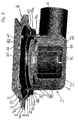
- the gully illustrated in the drawings is accordingly a floor gully, consisting of a floor gully member 1 and an extension ring member 2.
- the floor gully, the various members thereof and the various components therein, can be made entirely or partly of metal, e.g. cast iron, stainless steel etc., or of a suitable plastic material, unless otherwise specified.
- the floor gully member 1 includes, in the illustrated embodiment, a cup-shaped inlet portion 3, a tubular laterally directed outlet portion 4 which can be connected to a discharge pipe (not shown) and, through a transition 5, a substantially in radial direction protruding flange 6 on top of the inlet portion 3.
- the extension ring member 2 includes a tubular portion 7 protruding down into the inlet portion 3 of the floor gully member 1 and, through a transition 8, a flange 9 protruding substantially in a radial direction from the upper end 7a of the tubular portion 7 protruding upwards from said inlet portion 3.
- the transition 8 between the tubular portion 7 of the extension ring member 2 and the flange 9 thereof, is provided with a step 10 for a clamping ring 11 which is attached to the extension ring member 2 preferably by means of screws 12 which are screwed into screw attachments 13 in said step 10.
- a support 14 for a waterseal tongue 15 which together with a cup 17 which in the illustrated embodiment is snapped onto (snap-on-portions 16) the waterseal tongue 15 and rests on the bottom of the cup-shaped inlet portion 3, define the waterseal of the floor gully.
- the waterseal tongue 15 consists of a flange 20 which on top of the pipe piece 18 protrudes, through a transition 19, in a substantially radial direction and which with its edge portion 21 rests on the support 14.
- the edge portion 21 and the support 14 have been designed to fit closely together.
- a sealing ring 22 is provided on the underside of the flange 20 at the edge portion 21, clamped between a ring support 23 which is attached to the underside of the flange and a shank 24 on the support 14 for the waterseal tongue 15.
- This shank 24 extends substantially perpendicular to the shank 25 on the support 14 through which said support is located on the transition portion 8a between the step 10 and the tubular portion 7 of the extension ring member 2.
- a packing or gasket 26 is provided between said members.
- the floor gully member 1 with extension ring member 2 described above is located, during mounting thereof, in a suitable position on a location adapted for the floor gully in an arrangement of a suitable type (not shown) for constructing a floor structure.
- the floor gully is thereby provided with or will be provided with before the construction, i.e. preferably before casting is initiated, a protecting device in the form of a protective cover 27 which from above covers the tubular portion 7 and flange 9 of the extension ring member 2 and thereby, also the cup-shaped inlet portion 3 of the floor gully member 1, such that material from the construction, preferably cast compound, is prevented from falling down into the interior of the floor gully and get stuck therein.
- the protective cover 27 is thereby at the outer periphery thereof, provided with an edge piece 28 which grasps around the outer edge portions 6a, 9a of said flanges 6, 9.
- the edge piece 28 is defined by an outer edge portion of the protective cover 27 which is bent downwards, alternatively downwards and back towards the center of the protective cover substantially in parallel with and at a distance from the main portion 29 of the protective cover, i.e. bent about 180°.
- the edge piece 28 is preferably snapped onto the outer edge portions 6a, 9a of the flanges 6, 9, whereby the protective cover 27 is held in intended position.
- the edge piece or outer edge portion 28 defines in the alternative embodiment (not shown) at least one surrounding, inwardly open recess for the outer edge portions 6a, 9a of the flanges 6, 9, and achieves thus, a further improved attachment of the protective cover 27 to said flanges.
- the floor gully member 1 may initially be mounted on the intended location without the extension ring member 2.
- the protecting device in the form of the protective cover is in this alternative embodiment provided on the floor gully member 1 and the protective cover is at the outer periphery thereof provided with an edge piece which grasps around the outer edge portion 6a of the flange 6 of the floor gully member 1.
- the edge piece may be defined by an outer edge portion of the protective cover which is bent downwards substantially perpendicular to the main portion of the protective cover or is alternatively defined by an outer edge portion which is bent downwards and back towards the center of the protective cover substantially in parallel with and at a distance from the main portion of said protective cover in order to define at least one surrounding, inwardly open recess for the outer edge portion 6a of the flange 6.
- the construction of the floor structure starts with a first construction or build-up step which is continued until the floor structure has been built up to (the cast compound reaches) a level just beneath the flange 6 of the floor gully member 1, whereby said floor gully member 1 is immovably fixed in the material for the floor structure.
- the extension ring member 2 when present from the beginning, is held temporarily fixed to the floor gully member 1 in a first position in which the flanges 9 and 6 respectively, of said members extend substantially in parallel adjacent each other. This is accomplished by a first fixing means.
- This fixing means may be a first fixing means which preferably is designed to grasp around at least parts of outer edge portions 6a, 9a of the flanges 6 and 9 respectively, of the floor gully member 1 and the extension ring member 2 and hold the flanges in said position substantially in parallel with each other.
- the first fixing means may to this end have any suitable shape, e.g. consist of one or more clamps of varying circular section extension.
- the first fixing means is defined by said protective cover 27 which protects the interior of the floor gully from material from the construction of the floor structure, i.e. preferably cast compound such as concrete, and which due to its design provides for good fixation of the extension ring member 2 to the floor gully member 1.
- the protective cover 27 is removed from the flanges 6 and 9 respectively, of the floor gully member 1 and the extension ring member 2. If the protective cover is not designed to grasp around both flanges 6, 9 of said members 1, 2, but e.g. only grasps around the flange 9 of the extension ring member 2, the protective cover may remain seated thereon until the construction of the floor structure is entirely completed. The risk however, that material from said construction shall fall down into the interior of the floor gully after completion of the first build-up step is small. At the abovementioned alternative method where the extension ring member 2 initially is missing, the protective cover must be removed. If there are first fixing means of another type than said protective cover, these might eventually also have to be removed.
- the extension ring member 2 When the protective cover has been removed, the extension ring member 2, when initially not present, is located in the floor gully member 1. With the extension ring member 2 in position in the floor gully member 1, the extension ring member 2 is adjusted as required relative to the floor gully member 1. Adjustment is needed if the floor gully in any way has been dislodged from the preferably substantially horizontal position in which it was placed before the construction of the floor structure started and/or if the future floor surface will lie on another level than that where the flange 9 of the extension ring member 2 is found after the first build-up step. Adjustment is then carried through to a second position in which the flange 9 of the extension ring member 2 extends substantially horizontally and flush with the future floor surface.
- a second construction or build-up step is carried through; here preferably also casting with concrete as cast compound or filling with putty compound or filler.
- the extension ring member 2 is held temporarily fixed to the floor gully member 1 in said horizontal position until, through said second build-up step, the extension ring member 2 is finally fixed in the horizontal position with the flange 9 thereof flush with the floor surface or top surface of the floor structure.
- the second build-up step is carried through with the help of a fixing means of a suitable type.
- this fixing means may, as in the illustrated embodiment, be a second fixing means which is a complement to the first fixing means.
- this fixing means may be the same fixing means which during said first build-up step held the extension ring member temporarily fixed to the floor gully member in said first position with the flanges 6, 9 of said members running substantially in parallel adjacent each other.
- this second fixing means or alternatively, said one and same fixing means, is designed to resiliently or elastically yielding engage, from the outside, the tubular portion 7 of the extension ring member 2. It will hereby be possible during adjustment of the extension ring member 2 relative to the floor gully member 1 before the second build-up step is initiated, to turn and rotate the extension ring member 2 as required and tilt it relative to the floor gully member 1 if necessary, while simultaneously the fixing means engages the extension ring member 2 with such force that it effectively retains the extension ring member in any new set position.
- the fixing means preferably consists of an annular gasket or elastic material, e.g.
- the abovementioned gasket 26 for sealing between the floor gully member 1 and the extension ring member 2.
- said gasket 26 is provided on a step 30 in the transition 5 between the cup-shaped inlet portion 3 of the floor gully member 1 and its flange 6.
- the gasket 26 preferably has a radially inwards directed sealing lip 26a which resiliently engages the outside of the tubular portion 7 of the extension ring member 2, and a radially outwardly directed sealing lip 26b which resiliently engages a step surface 30a substantially opposite to the tubular portion 7 of the extension ring member 2.
- a preferably annular gasket support 31 is provided, which in the illustrated embodiment is attached to a transition surface 5a between the step 30 (step surface 30a) and the flange 6 on the floor gully member 1 and designed such that it protrudes radially inwards towards the extension ring member 2 and engages the gasket 26 from above.
- the gasket support 31 may be designed in other ways. Instead of covering the entire gasket 26 from above, the gasket support may alternatively consist of e.g. three or four tongue-like support portions (not shown) with the same cross-sectional shape as the gasket support 31 and with the same location.
- the protective cover 27 is removed if this has not been done previously.
- a floor mat or sealing mat (not shown) is laid on top of the floor structure and is inserted into the floor gully and clamped under the clamping ring 11 therein in a conventional manner.
- a removable grating is then placed on top of the clamping ring 11 or, if e.g. a clinker floor shall be laid on top of the sealing mat, a transition ring 32 with a removable grating 33.
- the gully and its various members and the components thereto may, as defined, be designed and arranged in many different ways, and the material they can be made of may also vary.
- the gully may e.g. be another gully than a floor gully (e.g. a roof gully) and also of another type than side-dumping (e.g. bottom dumping).
- the floor structure may instead be a roof structure.
Landscapes
- Health & Medical Sciences (AREA)
- Life Sciences & Earth Sciences (AREA)
- Engineering & Computer Science (AREA)
- Hydrology & Water Resources (AREA)
- Public Health (AREA)
- Water Supply & Treatment (AREA)
- Floor Finish (AREA)
- Sink And Installation For Waste Water (AREA)
Applications Claiming Priority (4)
| Application Number | Priority Date | Filing Date | Title |
|---|---|---|---|
| SE0200773 | 2002-03-15 | ||
| SE0200773A SE521542C2 (sv) | 2002-03-15 | 2002-03-15 | Förfarande och anordning vid avloppsbrunn med fixeringsorgan för förhöjningsrigen |
| SE0203794A SE525467C2 (sv) | 2002-12-20 | 2002-12-20 | Förfarande och anordningar vid avloppsbrunn med fixeringsorgan för förhöjningsringen |
| SE0203794 | 2002-12-20 |
Publications (2)
| Publication Number | Publication Date |
|---|---|
| EP1344874A2 true EP1344874A2 (de) | 2003-09-17 |
| EP1344874A3 EP1344874A3 (de) | 2004-11-24 |
Family
ID=26655685
Family Applications (1)
| Application Number | Title | Priority Date | Filing Date |
|---|---|---|---|
| EP20030005080 Withdrawn EP1344874A3 (de) | 2002-03-15 | 2003-03-07 | Methoden und Vorrichtungen an einem Gully mit Befestigungsmitteln für einen Zwischenring |
Country Status (2)
| Country | Link |
|---|---|
| EP (1) | EP1344874A3 (de) |
| NO (1) | NO20031081L (de) |
Cited By (6)
| Publication number | Priority date | Publication date | Assignee | Title |
|---|---|---|---|---|
| EP1705300A1 (de) * | 2005-03-18 | 2006-09-27 | Etienne Camerman | Bodenablauf mit integriertem Siphon |
| WO2007028936A1 (en) * | 2005-09-08 | 2007-03-15 | Dlp Limited | Flexible-wet-floor drain having tiling adaptor |
| EP1806456A3 (de) * | 2006-01-10 | 2008-05-21 | Blücher Metal A/S | Bodenablauf |
| EP2149643A2 (de) | 2008-07-28 | 2010-02-03 | VIEGA GmbH & Co. KG. | Ablaufgarnitur mit einem einen flexiblen Behälter aufweisenden Geruchverschluss |
| US10711447B2 (en) | 2016-09-12 | 2020-07-14 | Zurn Industries, Llc | Adjustable floor drain and method of installation |
| US11078658B2 (en) | 2018-04-17 | 2021-08-03 | Zurn Industries, Llc | Cover assembly and methods |
Family Cites Families (4)
| Publication number | Priority date | Publication date | Assignee | Title |
|---|---|---|---|---|
| DE9003326U1 (de) * | 1990-03-21 | 1990-06-13 | Kessel, Bernhard, 8071 Lenting | Bodenablauf |
| DE4013775A1 (de) * | 1990-04-28 | 1991-11-07 | Dallmer Gmbh & Co | Ablaufarmatur fuer einen fliesenfussboden |
| DE4406782B4 (de) * | 1994-03-02 | 2004-07-15 | Dallmer Gmbh & Co. Kg | Ablaufarmatur für Fußböden und Decken |
| US5921282A (en) * | 1997-04-16 | 1999-07-13 | Tci Products | Protective cover for plumbing fixtures |
-
2003
- 2003-03-07 EP EP20030005080 patent/EP1344874A3/de not_active Withdrawn
- 2003-03-10 NO NO20031081A patent/NO20031081L/no not_active Application Discontinuation
Non-Patent Citations (1)
| Title |
|---|
| None * |
Cited By (11)
| Publication number | Priority date | Publication date | Assignee | Title |
|---|---|---|---|---|
| EP1705300A1 (de) * | 2005-03-18 | 2006-09-27 | Etienne Camerman | Bodenablauf mit integriertem Siphon |
| WO2007028936A1 (en) * | 2005-09-08 | 2007-03-15 | Dlp Limited | Flexible-wet-floor drain having tiling adaptor |
| EP1806456A3 (de) * | 2006-01-10 | 2008-05-21 | Blücher Metal A/S | Bodenablauf |
| EP2149643A2 (de) | 2008-07-28 | 2010-02-03 | VIEGA GmbH & Co. KG. | Ablaufgarnitur mit einem einen flexiblen Behälter aufweisenden Geruchverschluss |
| EP2149643A3 (de) * | 2008-07-28 | 2011-05-11 | VIEGA GmbH & Co. KG | Ablaufgarnitur mit einem einen flexiblen Behälter aufweisenden Geruchverschluss |
| US10711447B2 (en) | 2016-09-12 | 2020-07-14 | Zurn Industries, Llc | Adjustable floor drain and method of installation |
| US11268271B2 (en) | 2016-09-12 | 2022-03-08 | Zurn Industries, Llc | Adjustable floor drain |
| US11591787B2 (en) | 2016-09-12 | 2023-02-28 | Zurn Industries, Llc | Adjustable floor drain and method of installation |
| US11828055B2 (en) | 2016-09-12 | 2023-11-28 | Zurn Industries, Llc | Adjustable floor drain and method of installation |
| US11078658B2 (en) | 2018-04-17 | 2021-08-03 | Zurn Industries, Llc | Cover assembly and methods |
| US12366063B2 (en) | 2018-04-17 | 2025-07-22 | Zurn Water, Llc | Cover assembly and methods |
Also Published As
| Publication number | Publication date |
|---|---|
| NO20031081L (no) | 2003-09-16 |
| NO20031081D0 (no) | 2003-03-10 |
| EP1344874A3 (de) | 2004-11-24 |
Similar Documents
| Publication | Publication Date | Title |
|---|---|---|
| US6350373B1 (en) | Adjustable drain apparatus | |
| US8658033B2 (en) | Method and system for installing a drain | |
| US6524026B2 (en) | Adjustable height utility access device | |
| US8096002B2 (en) | Height adjustable shower waste | |
| EP1222339B1 (de) | Baukonstruktion mit Ablauf und Verfahren dafür | |
| US9687118B2 (en) | Carrier body for sanitary surface material, method of adapting such a carrier body to floor dimensions of a sanitary shower facility, and use of the carrier body | |
| US6457901B1 (en) | Adjustable manhole apparatus | |
| US4886302A (en) | Repair flange | |
| CA2490750C (en) | Floor drain support plate | |
| EP1344874A2 (de) | Methoden und Vorrichtungen an einem Gully mit Befestigungsmitteln für einen Zwischenring | |
| US7958686B1 (en) | Drain body support pan | |
| EP1148177A1 (de) | Gully - bzw. Strassenschachtdeckeleinheit | |
| US9290925B2 (en) | Floor drain stabilizer ring | |
| US20160208504A1 (en) | Safety railing for building construction | |
| AU752345B1 (en) | A device for a waste water outlet | |
| KR19990084000A (ko) | 높이 조절 유니트 및 이를 이용한 맨홀의 높이 조절방법 | |
| JP4117750B2 (ja) | 地下構造物用下桝および地下構造物用蓋 | |
| JP3248420U (ja) | 配管埋込支援治具 | |
| JPH082185Y2 (ja) | マンホールのコンクリート打込施工装置 | |
| NO345772B1 (en) | Method for mounting a floor drain assembly and a floor drain assembly | |
| JP2009235727A (ja) | 排水用ドレインの保持装置 | |
| KR200164190Y1 (ko) | 거푸집 지지용 철사 결속구 | |
| GB2155967A (en) | Drainage trap | |
| KR101791864B1 (ko) | 다중 체결 구조를 갖는 맨홀 | |
| AU778163B2 (en) | Connection device |
Legal Events
| Date | Code | Title | Description |
|---|---|---|---|
| PUAI | Public reference made under article 153(3) epc to a published international application that has entered the european phase |
Free format text: ORIGINAL CODE: 0009012 |
|
| AK | Designated contracting states |
Kind code of ref document: A2 Designated state(s): AT BE BG CH CY CZ DE DK EE ES FI FR GB GR HU IE IT LI LU MC NL PT RO SE SI SK TR |
|
| AX | Request for extension of the european patent |
Extension state: AL LT LV MK |
|
| PUAL | Search report despatched |
Free format text: ORIGINAL CODE: 0009013 |
|
| AK | Designated contracting states |
Kind code of ref document: A3 Designated state(s): AT BE BG CH CY CZ DE DK EE ES FI FR GB GR HU IE IT LI LU MC NL PT RO SE SI SK TR |
|
| AX | Request for extension of the european patent |
Extension state: AL LT LV MK |
|
| 17P | Request for examination filed |
Effective date: 20050518 |
|
| AKX | Designation fees paid |
Designated state(s): AT BE BG CH CY CZ DE DK EE ES FI FR GB GR HU IE IT LI LU MC NL PT RO SE SI SK TR |
|
| 17Q | First examination report despatched |
Effective date: 20080922 |
|
| R17C | First examination report despatched (corrected) |
Effective date: 20080922 |
|
| GRAP | Despatch of communication of intention to grant a patent |
Free format text: ORIGINAL CODE: EPIDOSNIGR1 |
|
| INTG | Intention to grant announced |
Effective date: 20170405 |
|
| STAA | Information on the status of an ep patent application or granted ep patent |
Free format text: STATUS: THE APPLICATION IS DEEMED TO BE WITHDRAWN |
|
| 18D | Application deemed to be withdrawn |
Effective date: 20170817 |
|
| RIC1 | Information provided on ipc code assigned before grant |
Ipc: E03F 5/04 20060101AFI20030703BHEP |