EP1345749B1 - Procedes et appareil d'extrusion d'un film tubulaire - Google Patents
Procedes et appareil d'extrusion d'un film tubulaire Download PDFInfo
- Publication number
- EP1345749B1 EP1345749B1 EP01983566A EP01983566A EP1345749B1 EP 1345749 B1 EP1345749 B1 EP 1345749B1 EP 01983566 A EP01983566 A EP 01983566A EP 01983566 A EP01983566 A EP 01983566A EP 1345749 B1 EP1345749 B1 EP 1345749B1
- Authority
- EP
- European Patent Office
- Prior art keywords
- flow
- die
- channels
- exit orifice
- joining
- Prior art date
- Legal status (The legal status is an assumption and is not a legal conclusion. Google has not performed a legal analysis and makes no representation as to the accuracy of the status listed.)
- Expired - Lifetime
Links
- 238000000034 method Methods 0.000 title claims description 29
- 239000002861 polymer material Substances 0.000 claims description 36
- 238000005304 joining Methods 0.000 claims description 30
- 230000008569 process Effects 0.000 claims description 24
- 238000001125 extrusion Methods 0.000 claims description 19
- 239000000463 material Substances 0.000 claims description 15
- 238000001816 cooling Methods 0.000 claims description 11
- 229920001169 thermoplastic Polymers 0.000 claims description 10
- 239000000155 melt Substances 0.000 claims description 6
- 238000007493 shaping process Methods 0.000 claims description 5
- 239000002826 coolant Substances 0.000 claims description 3
- 230000001747 exhibiting effect Effects 0.000 claims 1
- 239000010408 film Substances 0.000 description 44
- 229920006178 high molecular weight high density polyethylene Polymers 0.000 description 10
- 238000009826 distribution Methods 0.000 description 9
- 239000010410 layer Substances 0.000 description 9
- 230000008901 benefit Effects 0.000 description 7
- 238000010276 construction Methods 0.000 description 7
- 239000002344 surface layer Substances 0.000 description 7
- 229920001577 copolymer Polymers 0.000 description 6
- 238000009413 insulation Methods 0.000 description 6
- 238000012986 modification Methods 0.000 description 6
- 230000004048 modification Effects 0.000 description 6
- -1 polypropylenes Polymers 0.000 description 5
- 238000011144 upstream manufacturing Methods 0.000 description 5
- 239000004743 Polypropylene Substances 0.000 description 4
- 238000013461 design Methods 0.000 description 4
- 238000004519 manufacturing process Methods 0.000 description 4
- 238000002844 melting Methods 0.000 description 4
- 230000008018 melting Effects 0.000 description 4
- 229920001155 polypropylene Polymers 0.000 description 4
- 238000012360 testing method Methods 0.000 description 4
- 238000005516 engineering process Methods 0.000 description 3
- 239000012528 membrane Substances 0.000 description 3
- 238000003491 array Methods 0.000 description 2
- 239000011248 coating agent Substances 0.000 description 2
- 238000000576 coating method Methods 0.000 description 2
- 229920001038 ethylene copolymer Polymers 0.000 description 2
- 239000011796 hollow space material Substances 0.000 description 2
- 239000011810 insulating material Substances 0.000 description 2
- 230000001788 irregular Effects 0.000 description 2
- 229920000642 polymer Polymers 0.000 description 2
- 238000000518 rheometry Methods 0.000 description 2
- XLYOFNOQVPJJNP-UHFFFAOYSA-N water Substances O XLYOFNOQVPJJNP-UHFFFAOYSA-N 0.000 description 2
- 229910000906 Bronze Inorganic materials 0.000 description 1
- VGGSQFUCUMXWEO-UHFFFAOYSA-N Ethene Chemical compound C=C VGGSQFUCUMXWEO-UHFFFAOYSA-N 0.000 description 1
- 239000005977 Ethylene Substances 0.000 description 1
- 229920010126 Linear Low Density Polyethylene (LLDPE) Polymers 0.000 description 1
- 239000004698 Polyethylene Substances 0.000 description 1
- 229910000831 Steel Inorganic materials 0.000 description 1
- 229920006362 Teflon® Polymers 0.000 description 1
- 230000001154 acute effect Effects 0.000 description 1
- 230000004323 axial length Effects 0.000 description 1
- 239000010974 bronze Substances 0.000 description 1
- 230000015556 catabolic process Effects 0.000 description 1
- 230000008859 change Effects 0.000 description 1
- 238000004140 cleaning Methods 0.000 description 1
- 239000002131 composite material Substances 0.000 description 1
- KUNSUQLRTQLHQQ-UHFFFAOYSA-N copper tin Chemical compound [Cu].[Sn] KUNSUQLRTQLHQQ-UHFFFAOYSA-N 0.000 description 1
- 238000006731 degradation reaction Methods 0.000 description 1
- 230000001419 dependent effect Effects 0.000 description 1
- 238000011161 development Methods 0.000 description 1
- 230000018109 developmental process Effects 0.000 description 1
- 238000006073 displacement reaction Methods 0.000 description 1
- 238000007765 extrusion coating Methods 0.000 description 1
- 238000010438 heat treatment Methods 0.000 description 1
- 238000003475 lamination Methods 0.000 description 1
- 238000005259 measurement Methods 0.000 description 1
- 239000002184 metal Substances 0.000 description 1
- 239000012768 molten material Substances 0.000 description 1
- 230000002093 peripheral effect Effects 0.000 description 1
- 229920000573 polyethylene Polymers 0.000 description 1
- 238000003825 pressing Methods 0.000 description 1
- 230000001105 regulatory effect Effects 0.000 description 1
- 238000007711 solidification Methods 0.000 description 1
- 230000008023 solidification Effects 0.000 description 1
- 230000003019 stabilising effect Effects 0.000 description 1
- 239000010959 steel Substances 0.000 description 1
- 239000012815 thermoplastic material Substances 0.000 description 1
- 239000010409 thin film Substances 0.000 description 1
- 238000012546 transfer Methods 0.000 description 1
- 229940117958 vinyl acetate Drugs 0.000 description 1
- 238000003466 welding Methods 0.000 description 1
Images


Classifications
-
- A—HUMAN NECESSITIES
- A23—FOODS OR FOODSTUFFS; TREATMENT THEREOF, NOT COVERED BY OTHER CLASSES
- A23G—COCOA; COCOA PRODUCTS, e.g. CHOCOLATE; SUBSTITUTES FOR COCOA OR COCOA PRODUCTS; CONFECTIONERY; CHEWING GUM; ICE-CREAM; PREPARATION THEREOF
- A23G3/00—Sweetmeats; Confectionery; Marzipan; Coated or filled products
- A23G3/02—Apparatus specially adapted for manufacture or treatment of sweetmeats or confectionery; Accessories therefor
- A23G3/20—Apparatus for coating or filling sweetmeats or confectionery
- A23G3/2007—Manufacture of filled articles, composite articles, multi-layered articles
- A23G3/2015—Manufacture of filled articles, composite articles, multi-layered articles the material being shaped at least partially by a die; Extrusion of filled or multi-layered cross-sections or plates, optionally with the associated cutting device
-
- A—HUMAN NECESSITIES
- A21—BAKING; EDIBLE DOUGHS
- A21C—MACHINES OR EQUIPMENT FOR MAKING OR PROCESSING DOUGHS; HANDLING BAKED ARTICLES MADE FROM DOUGH
- A21C11/00—Other machines for forming the dough into its final shape before cooking or baking
- A21C11/16—Extruding machines
- A21C11/163—Applying co-extrusion, i.e. extruding two or more plastic substances simultaneously, e.g. for making filled dough products; Making products from two or more different substances supplied to the extruder
-
- A—HUMAN NECESSITIES
- A23—FOODS OR FOODSTUFFS; TREATMENT THEREOF, NOT COVERED BY OTHER CLASSES
- A23G—COCOA; COCOA PRODUCTS, e.g. CHOCOLATE; SUBSTITUTES FOR COCOA OR COCOA PRODUCTS; CONFECTIONERY; CHEWING GUM; ICE-CREAM; PREPARATION THEREOF
- A23G9/00—Frozen sweets, e.g. ice confectionery, ice-cream; Mixtures therefor
- A23G9/04—Production of frozen sweets, e.g. ice-cream
- A23G9/22—Details, component parts or accessories of apparatus insofar as not peculiar to a single one of the preceding groups
- A23G9/28—Details, component parts or accessories of apparatus insofar as not peculiar to a single one of the preceding groups for portioning or dispensing
- A23G9/281—Details, component parts or accessories of apparatus insofar as not peculiar to a single one of the preceding groups for portioning or dispensing at the discharge end of freezing chambers
- A23G9/285—Details, component parts or accessories of apparatus insofar as not peculiar to a single one of the preceding groups for portioning or dispensing at the discharge end of freezing chambers for extruding strips, cutting blocks and manipulating cut blocks
-
- A—HUMAN NECESSITIES
- A23—FOODS OR FOODSTUFFS; TREATMENT THEREOF, NOT COVERED BY OTHER CLASSES
- A23P—SHAPING OR WORKING OF FOODSTUFFS, NOT FULLY COVERED BY A SINGLE OTHER SUBCLASS
- A23P30/00—Shaping or working of foodstuffs characterised by the process or apparatus
- A23P30/20—Extruding
- A23P30/25—Co-extrusion of different foodstuffs
-
- B—PERFORMING OPERATIONS; TRANSPORTING
- B29—WORKING OF PLASTICS; WORKING OF SUBSTANCES IN A PLASTIC STATE IN GENERAL
- B29C—SHAPING OR JOINING OF PLASTICS; SHAPING OF MATERIAL IN A PLASTIC STATE, NOT OTHERWISE PROVIDED FOR; AFTER-TREATMENT OF THE SHAPED PRODUCTS, e.g. REPAIRING
- B29C48/00—Extrusion moulding, i.e. expressing the moulding material through a die or nozzle which imparts the desired form; Apparatus therefor
- B29C48/03—Extrusion moulding, i.e. expressing the moulding material through a die or nozzle which imparts the desired form; Apparatus therefor characterised by the shape of the extruded material at extrusion
- B29C48/07—Flat, e.g. panels
- B29C48/08—Flat, e.g. panels flexible, e.g. films
-
- B—PERFORMING OPERATIONS; TRANSPORTING
- B29—WORKING OF PLASTICS; WORKING OF SUBSTANCES IN A PLASTIC STATE IN GENERAL
- B29C—SHAPING OR JOINING OF PLASTICS; SHAPING OF MATERIAL IN A PLASTIC STATE, NOT OTHERWISE PROVIDED FOR; AFTER-TREATMENT OF THE SHAPED PRODUCTS, e.g. REPAIRING
- B29C48/00—Extrusion moulding, i.e. expressing the moulding material through a die or nozzle which imparts the desired form; Apparatus therefor
- B29C48/03—Extrusion moulding, i.e. expressing the moulding material through a die or nozzle which imparts the desired form; Apparatus therefor characterised by the shape of the extruded material at extrusion
- B29C48/09—Articles with cross-sections having partially or fully enclosed cavities, e.g. pipes or channels
- B29C48/10—Articles with cross-sections having partially or fully enclosed cavities, e.g. pipes or channels flexible, e.g. blown foils
-
- B—PERFORMING OPERATIONS; TRANSPORTING
- B29—WORKING OF PLASTICS; WORKING OF SUBSTANCES IN A PLASTIC STATE IN GENERAL
- B29C—SHAPING OR JOINING OF PLASTICS; SHAPING OF MATERIAL IN A PLASTIC STATE, NOT OTHERWISE PROVIDED FOR; AFTER-TREATMENT OF THE SHAPED PRODUCTS, e.g. REPAIRING
- B29C48/00—Extrusion moulding, i.e. expressing the moulding material through a die or nozzle which imparts the desired form; Apparatus therefor
- B29C48/16—Articles comprising two or more components, e.g. co-extruded layers
- B29C48/18—Articles comprising two or more components, e.g. co-extruded layers the components being layers
- B29C48/21—Articles comprising two or more components, e.g. co-extruded layers the components being layers the layers being joined at their surfaces
-
- B—PERFORMING OPERATIONS; TRANSPORTING
- B29—WORKING OF PLASTICS; WORKING OF SUBSTANCES IN A PLASTIC STATE IN GENERAL
- B29C—SHAPING OR JOINING OF PLASTICS; SHAPING OF MATERIAL IN A PLASTIC STATE, NOT OTHERWISE PROVIDED FOR; AFTER-TREATMENT OF THE SHAPED PRODUCTS, e.g. REPAIRING
- B29C48/00—Extrusion moulding, i.e. expressing the moulding material through a die or nozzle which imparts the desired form; Apparatus therefor
- B29C48/25—Component parts, details or accessories; Auxiliary operations
- B29C48/255—Flow control means, e.g. valves
- B29C48/2556—Flow control means, e.g. valves provided in or in the proximity of dies
-
- B—PERFORMING OPERATIONS; TRANSPORTING
- B29—WORKING OF PLASTICS; WORKING OF SUBSTANCES IN A PLASTIC STATE IN GENERAL
- B29C—SHAPING OR JOINING OF PLASTICS; SHAPING OF MATERIAL IN A PLASTIC STATE, NOT OTHERWISE PROVIDED FOR; AFTER-TREATMENT OF THE SHAPED PRODUCTS, e.g. REPAIRING
- B29C48/00—Extrusion moulding, i.e. expressing the moulding material through a die or nozzle which imparts the desired form; Apparatus therefor
- B29C48/25—Component parts, details or accessories; Auxiliary operations
- B29C48/30—Extrusion nozzles or dies
- B29C48/305—Extrusion nozzles or dies having a wide opening, e.g. for forming sheets
- B29C48/307—Extrusion nozzles or dies having a wide opening, e.g. for forming sheets specially adapted for bringing together components, e.g. melts within the die
-
- B—PERFORMING OPERATIONS; TRANSPORTING
- B29—WORKING OF PLASTICS; WORKING OF SUBSTANCES IN A PLASTIC STATE IN GENERAL
- B29C—SHAPING OR JOINING OF PLASTICS; SHAPING OF MATERIAL IN A PLASTIC STATE, NOT OTHERWISE PROVIDED FOR; AFTER-TREATMENT OF THE SHAPED PRODUCTS, e.g. REPAIRING
- B29C48/00—Extrusion moulding, i.e. expressing the moulding material through a die or nozzle which imparts the desired form; Apparatus therefor
- B29C48/25—Component parts, details or accessories; Auxiliary operations
- B29C48/30—Extrusion nozzles or dies
- B29C48/305—Extrusion nozzles or dies having a wide opening, e.g. for forming sheets
- B29C48/31—Extrusion nozzles or dies having a wide opening, e.g. for forming sheets being adjustable, i.e. having adjustable exit sections
- B29C48/313—Extrusion nozzles or dies having a wide opening, e.g. for forming sheets being adjustable, i.e. having adjustable exit sections by positioning the die lips
-
- B—PERFORMING OPERATIONS; TRANSPORTING
- B29—WORKING OF PLASTICS; WORKING OF SUBSTANCES IN A PLASTIC STATE IN GENERAL
- B29C—SHAPING OR JOINING OF PLASTICS; SHAPING OF MATERIAL IN A PLASTIC STATE, NOT OTHERWISE PROVIDED FOR; AFTER-TREATMENT OF THE SHAPED PRODUCTS, e.g. REPAIRING
- B29C48/00—Extrusion moulding, i.e. expressing the moulding material through a die or nozzle which imparts the desired form; Apparatus therefor
- B29C48/25—Component parts, details or accessories; Auxiliary operations
- B29C48/30—Extrusion nozzles or dies
- B29C48/32—Extrusion nozzles or dies with annular openings, e.g. for forming tubular articles
- B29C48/325—Extrusion nozzles or dies with annular openings, e.g. for forming tubular articles being adjustable, i.e. having adjustable exit sections
-
- B—PERFORMING OPERATIONS; TRANSPORTING
- B29—WORKING OF PLASTICS; WORKING OF SUBSTANCES IN A PLASTIC STATE IN GENERAL
- B29C—SHAPING OR JOINING OF PLASTICS; SHAPING OF MATERIAL IN A PLASTIC STATE, NOT OTHERWISE PROVIDED FOR; AFTER-TREATMENT OF THE SHAPED PRODUCTS, e.g. REPAIRING
- B29C48/00—Extrusion moulding, i.e. expressing the moulding material through a die or nozzle which imparts the desired form; Apparatus therefor
- B29C48/25—Component parts, details or accessories; Auxiliary operations
- B29C48/30—Extrusion nozzles or dies
- B29C48/32—Extrusion nozzles or dies with annular openings, e.g. for forming tubular articles
- B29C48/335—Multiple annular extrusion nozzles in coaxial arrangement, e.g. for making multi-layered tubular articles
- B29C48/336—Multiple annular extrusion nozzles in coaxial arrangement, e.g. for making multi-layered tubular articles the components merging one by one down streams in the die
- B29C48/3363—Multiple annular extrusion nozzles in coaxial arrangement, e.g. for making multi-layered tubular articles the components merging one by one down streams in the die using a layered die, e.g. stacked discs
-
- B—PERFORMING OPERATIONS; TRANSPORTING
- B29—WORKING OF PLASTICS; WORKING OF SUBSTANCES IN A PLASTIC STATE IN GENERAL
- B29C—SHAPING OR JOINING OF PLASTICS; SHAPING OF MATERIAL IN A PLASTIC STATE, NOT OTHERWISE PROVIDED FOR; AFTER-TREATMENT OF THE SHAPED PRODUCTS, e.g. REPAIRING
- B29C48/00—Extrusion moulding, i.e. expressing the moulding material through a die or nozzle which imparts the desired form; Apparatus therefor
- B29C48/25—Component parts, details or accessories; Auxiliary operations
- B29C48/30—Extrusion nozzles or dies
- B29C48/32—Extrusion nozzles or dies with annular openings, e.g. for forming tubular articles
- B29C48/335—Multiple annular extrusion nozzles in coaxial arrangement, e.g. for making multi-layered tubular articles
- B29C48/337—Multiple annular extrusion nozzles in coaxial arrangement, e.g. for making multi-layered tubular articles the components merging at a common location
- B29C48/338—Multiple annular extrusion nozzles in coaxial arrangement, e.g. for making multi-layered tubular articles the components merging at a common location using a die with concentric parts, e.g. rings, cylinders
-
- B—PERFORMING OPERATIONS; TRANSPORTING
- B29—WORKING OF PLASTICS; WORKING OF SUBSTANCES IN A PLASTIC STATE IN GENERAL
- B29C—SHAPING OR JOINING OF PLASTICS; SHAPING OF MATERIAL IN A PLASTIC STATE, NOT OTHERWISE PROVIDED FOR; AFTER-TREATMENT OF THE SHAPED PRODUCTS, e.g. REPAIRING
- B29C48/00—Extrusion moulding, i.e. expressing the moulding material through a die or nozzle which imparts the desired form; Apparatus therefor
- B29C48/25—Component parts, details or accessories; Auxiliary operations
- B29C48/36—Means for plasticising or homogenising the moulding material or forcing it through the nozzle or die
- B29C48/475—Means for plasticising or homogenising the moulding material or forcing it through the nozzle or die using pistons, accumulators or press rams
-
- B—PERFORMING OPERATIONS; TRANSPORTING
- B29—WORKING OF PLASTICS; WORKING OF SUBSTANCES IN A PLASTIC STATE IN GENERAL
- B29C—SHAPING OR JOINING OF PLASTICS; SHAPING OF MATERIAL IN A PLASTIC STATE, NOT OTHERWISE PROVIDED FOR; AFTER-TREATMENT OF THE SHAPED PRODUCTS, e.g. REPAIRING
- B29C48/00—Extrusion moulding, i.e. expressing the moulding material through a die or nozzle which imparts the desired form; Apparatus therefor
- B29C48/25—Component parts, details or accessories; Auxiliary operations
- B29C48/36—Means for plasticising or homogenising the moulding material or forcing it through the nozzle or die
- B29C48/49—Means for plasticising or homogenising the moulding material or forcing it through the nozzle or die using two or more extruders to feed one die or nozzle
-
- B—PERFORMING OPERATIONS; TRANSPORTING
- B29—WORKING OF PLASTICS; WORKING OF SUBSTANCES IN A PLASTIC STATE IN GENERAL
- B29C—SHAPING OR JOINING OF PLASTICS; SHAPING OF MATERIAL IN A PLASTIC STATE, NOT OTHERWISE PROVIDED FOR; AFTER-TREATMENT OF THE SHAPED PRODUCTS, e.g. REPAIRING
- B29C48/00—Extrusion moulding, i.e. expressing the moulding material through a die or nozzle which imparts the desired form; Apparatus therefor
- B29C48/25—Component parts, details or accessories; Auxiliary operations
- B29C48/36—Means for plasticising or homogenising the moulding material or forcing it through the nozzle or die
- B29C48/50—Details of extruders
- B29C48/695—Flow dividers, e.g. breaker plates
- B29C48/70—Flow dividers, e.g. breaker plates comprising means for dividing, distributing and recombining melt flows
- B29C48/705—Flow dividers, e.g. breaker plates comprising means for dividing, distributing and recombining melt flows in the die zone, e.g. to create flow homogeneity
-
- B—PERFORMING OPERATIONS; TRANSPORTING
- B29—WORKING OF PLASTICS; WORKING OF SUBSTANCES IN A PLASTIC STATE IN GENERAL
- B29K—INDEXING SCHEME ASSOCIATED WITH SUBCLASSES B29B, B29C OR B29D, RELATING TO MOULDING MATERIALS OR TO MATERIALS FOR MOULDS, REINFORCEMENTS, FILLERS OR PREFORMED PARTS, e.g. INSERTS
- B29K2995/00—Properties of moulding materials, reinforcements, fillers, preformed parts or moulds
- B29K2995/0037—Other properties
- B29K2995/0072—Roughness, e.g. anti-slip
- B29K2995/0073—Roughness, e.g. anti-slip smooth
Definitions
- the present invention relates to methods and apparatus for extruding a tubular film of polymer material with provision for the circumferential equalisation of the material in helical grooves, extending generally in a plane or conically, formed in one or more generally planar or conical diepart surfaces, and guiding the flow of material outward.
- the invention aims at better utilisation of the special possibilities which this particular arrangement of the grooves offers.
- the space in the die can be very well utilized.
- the die can be made very compact, which has importance not only for saving of steel and easier assemblage and disessemblage, but also for quickly and safely achieving even temperatures.
- Tubular coextrusion of HMWHDPE with surface layers of copolymers of a much higher m.f.i. is commonly carried out in circular coextrusion dies in which the circumferential equalisation is established by a system of helical grooves (with overflow) which extend in a geometrical arrangement as along a cylindrical surface.
- the prior art dies use the planar or conical arrangements of the helical grooves, which as mentioned as several advantages are very unsuited e.g. for the coextrusion of HMWHDPE having m.f.i. 0.1 or lower, with ethylene copolymers, having m.f.i. 0.5 or higher (reference to ASTM D1238 condition E).
- polypropylenes of similar high melt viscosities as HMWHDPE with copolymers which in practice are applicable as surface layers on such polypropylene film.
- the invention is limited, as far as the method is concerned, to coextrusion of at least one thermoplastic polymer material A with at least two thermoplastic polymer materials B and C of a melt flow index (the test conditions are specified below) which is at least double that of A, B being applied on one and C on the other side of A.
- a melt flow index the test conditions are specified below
- at least the coextrusion of A follows the process defined above, and the coextrusion is characterised in that the joining of A with B is established at the same location as its joining with C or in the immediate vicinity thereof, and that A flows outward at least immediately before it joins with B and C, while B and C flow towards each other immediately before the joining.
- the coextrusion die for carrying out this process if similarly characterised, but its use is of course not limited to coextrusion of components with the defined relation between their rheologies.
- circumferential equalisation of polymer materials B and C should normally but not necessarily take place in similar way as the circumferential equalisation of A.
- a good equalisation of these surface components is not always required since each may occupy less than 15% or even less than 10% of the structure, and therefore simplified and less efficient, known means of circumferential equalisation may be applied.
- melt flow indices refers to the ASTM standard D 1238-90b. If the full melting range for each of the polymer materials is lower than 140°C condition E should be used (i.e. temperature of 190°C and load 2,16 kg). If the highest limit of the melting range of any of the polymer materials is from 140°C up to but less than 180°C condition L should be used (i.e. temperature 230°C and load 2,16 kg). If the highest limit of the melting range of any of the polymer materials is from 180°C up to 235°C condition W should be used (i.e. temperature 285°C and load 2,16 kg). It is not considered a practical possibility that the higher limit of any of the polymer materials will exceed 235°C.
- the invention is useful in particular for coextrusion of at least one middle layer consisting of polyethylene based material having melt flow index 1 or lower according to the mentioned condition E, said middle layer or layers constituting at least 50% of the coextruded film, and surface layers of higher m.f.i. as defined above.
- the condition that the part flows or channels must be of a generally helical form does not limit the invention to the regular helical form, e.g. the form following a two- or three dimensional curve defined by a point which moves at a constant angular velocity around another point in a plane or around an axis in the space, at the same time moving at a constant linear velocity and - if 3-dimensionally - with its projection on the axis also moving constantly.
- the regular helical form e.g. the form following a two- or three dimensional curve defined by a point which moves at a constant angular velocity around another point in a plane or around an axis in the space, at the same time moving at a constant linear velocity and - if 3-dimensionally - with its projection on the axis also moving constantly.
- a particularly regular form usually is very suitable for the shaping of the channels it is not needed for proper equalisation.
- there are many part flows e.g.
- the "generally helical" portion of each can be very short and can then be of linear shape under small angle to the tangent of a circle defined as crossing this short linear portion and formed by rotation of a point around the die axis.
- Another example of an irregular but generally helical form which can be suited for the shaping of the channels is a staggered form in which a first segment of a generally helical partflow follows a channel which is circular around the die axis, then just before this partflow would meet the adjacent partflow the channel bends to project the first mentioned partflow out into an "orbit" further apart from the die axis.
- the first aspect of the invention is not limited to coextrusion of three polymer materials.
- the coextrusion die can have more than three sets of channels as stated in claims 52 and 53.
- the part flows may extend in a generally planar manner or they may extend in a geometrical arrangement as along a circular conical surface.
- this should preferably be a right conical surface, i.e. its genetrix is a straight line, but the genetrix can also be curved, e.g. like a parabola with its axis parallel to the axis of the die but displaced from that axis.
- the tangent planes of the conical surface should preferably form an angle of at least 20° and more preferably 45° to the axis of the die at least over the most downstream part of said surface. In the case of a right conical surface these angles are the angles between the straight genetrix and the axis.
- Labyrinthine dividing means that a main flow branches out to two generally circularly arched equally long and mutually symmetrical first branch-flows, which together occupy essentially 50% of the circumference of the corresponding circle, whereafter each of the first branch-flows branch out to two, in similar way generally circularly arched second branch flows, these in total four second branch flows also occupying together essentially 50% of the circumference of the corresponding circle.
- the dividing may continue in similar manner to form 8 or 16 or 32 or even 64 part flows.
- the four second branch-flows may form four of the sides in a regular octagon
- the eight third branch-flows may form eight of the sides in a 16-sided regular polygon, etc.
- At least a part of the channels for the labyrinthine dividing may be formed integrally with the channels for the generally helical flow between the planar or conical surfaces of said first dieparts by grooves in at least one surface of a pair of contacting surfaces.
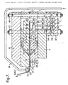
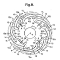
- At least the beginning of said labyrinthine dividing is established by use of second dieparts having generally planar or conical surfaces, the second dieparts being damped together with the first dieparts, the arrangement of channels for said beginning of the labyrinthine dividing being established partly by grooves in contacting surfaces between said second parts or between one second part and one first part and partly by interconnecting channels through said second and/or first parts. This is illustrated in figs. 7, 8 and 9.
- one of the coextruded polymer materials is susceptible to thermal degradation at a temperature which is in practice required for extrusion of one of the other coextruded materials it may be preferable or necessary to provide for thermal insulation between the dieparts which form the channel systems for the two polymer materials.
- One example of this is the coating on both sides of HMWHDPE of m.f.i. lower than 0,1 according to the above mentioned ASTM test with an ethylene/vinylacetate copolymer. This can conveniently be carried out with a coextrusion die like the die shown in fig. 2a and fig.
- the disc formed diepart 7a should be divided into two disc formed half parts with thermal insulation between the two, and similarly the disc formed diepart 7b should be divided into two disc formed half parts thermally insulated from each other.
- the thermal insulation is preferably established by means of airspaces, i.e.
- one or both half parts which together form 7a or 7b are supplied with ribs, recesses, knobs or the like, exactly machined so that the parts can be firmly and exactly damped together.
- This seal can e.g. be a ring of Teflon (trade mark) or bronze.
- a similar thermal insulation can be arranged when the dieparts 7a and 7b are conically shaped as in fig. 5.
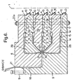
- the exit passageway may guide the common flow of the joined B, A and C further outward and then turn it in an axial direction, or the common passageway may without further outward passage immediately guide the common flow in a generally axial direction, in each case so that the joined materials flow generally axially when they meet the exit orifice.
- the first mentioned possibility is illustrated in figs 2a, 2b and 6, the last mentioned in fig. 12.
- a third possibility is that the exit passageway guides the common flow of B, A and C to the peripherical surface of the die, as shown in figs. 4a, 4b, 6 and 7, but this possibility is described more detailed below.
- the embodiment shown in fig. 12 is further characterised in that the helical grooves for circumferential equalisation of one surface component is formed in a cylindrical diepart surface. It could also be in two cylindrical surfaces facing each other or these surfaces could be conical but rather dose to the cylindrical shape, e.g. their genetrix could form an angle of no more than 30° to the axis. In this way it becomes practically possible to make the common exit passageway cylindrical right from its start and therefore minimize its length and the pressure drop in the material from the time of joining to the exit orifice. This pressure drop has importance for the circumferential equalisation of the surface components when their melt viscosities are significantly lower than that of the middle component, a low pressure drop being preferable.
- the embodiment of the invention which is illustrated in figs. 4a, 4b and 5, is characterised in that the exit passageway conducts the molten material right to the peripherical surface of the die, where the exit orifice is located, and the tubular film leaves the exit orifice under an angle of at least 20° to the axis of the die, and an adjusted overpressure is applied inside the tubular film to establish the desired diameter of the tube while it is drawn down and solidified.
- Expressly disclaimed is therefore the application of a similar assembly of dieparts to make a tube, which immediately upon leaving said parts is delivered to the to the inside of a conveying mold as in WO-A-00/07801 (Neubauer).
- the tubular film leaving the die from its periphery may directly be blown as it is normal in the extrusion of a tubular film by the inside air which is kept under an overpressure, feedback controlled from an automatic registration of the diameter, while the film is drawn down in thickness and drawn away in the axial direction by conventional means (driven rollers, collapsing frame etc).
- the tubular film which in molten state has left the peripheral surface of the die should meet a ring which is concentric with the die and in fixed relation to the latter, so that the angle between the axis of the die and the direction of movement of the film is reduced and a frictional force is set up between the ring and the film to assist in a molecular orientation of the film, while the latter is drawn over the ring.
- meltorientation is important e.g. when the film is used for manufacture of cross-laminates.
- tubular film can be cut in a helical manner prior to lamination, in well-known manner, and can be further oriented at different stages of the manufacturing process, as it also is well-known, see e.g. EP-A-0624126 (Rasmussen).
- this embodiment of the invention has the advantage that the channels from termination of the circumferential equalisation to the exit orifice, and in case of coextrusion from the location of joining of the different polymer materials to the exit orifice, can be reduced to a minimum.
- the ring should preferably be cooled in order to avoid the tubular film adhering too strongly to it, but in the case of particularly thick film this is not always necessary.
- the cooling can be by means of circulating water or oil of a suitable temperature. If the surface of the ring has a temperature below the lower limit of the melting range of the polymer material which is contacts, a thin region of the film will solidify and can thereby avoid or reduce the tendency to adhesion. This solidification will normally be temporary so that the thin region of the film melts again when the film has left the ring.
- a person skilled in the art may decide how the cooling conditions best are adjusted (or if cooling is needed at all) to achieve the optional orientation whilst minimising the risk of production stops due to adhesion of the film to the ring.
- the circulation of the cooling medium can preferably be by leading the medium in and out through a suitable number of pipes which pass through the hollow cavity around the axis of the die.
- the coextrusion may conveniently be carried out without joining the polymer materials inside the die, but letting them fuse together while they meet on the ring.
- cooling of the ring may not be enough to avoid too much adhesion or excessive friction seen in relation to the strength of the film while the latter passes over the outside of the ring.
- the ring may be adapted to carry the film on an "air pillow", i.e. pressurized air is blown into the film from an inside space in the ring through closely spaced fine holes in one or more circular arrays around the part of the ring which is directly adjacent to the film.
- air pillow i.e. pressurized air is blown into the film from an inside space in the ring through closely spaced fine holes in one or more circular arrays around the part of the ring which is directly adjacent to the film.
- This air is preferably cooled air so that it also acts as an efficient medium for internal cooling.
- the ring must be adapted for efficient circumferential equalisation of the flow of compressed air before this air meets the circular array or arrays of fine holes. It is preferably conducted from the compressor and the refrigerator through one or preferably more pipes going through the hollow cavity around the axis of the die, and it leaves the die through at least one other pipe connected to the inner of the film bubble. (The cavity around the axis of the die is of course closed off from the environment so that an overpressure can be maintained inside the bubble). There is a valve at the outlet of this air to control the pressure in the bubble.
- the exchangeable insert can be an insert-shim (8a) by' means of which the distance between the two channel forming dieparts can be regulated, shaped in such a manner that it prevents overflow between channel parts where such overflow must be prevented and allows it where it is wanted.
- fig. 3 which corresponds to fig.
- the upstream limit of the area where overflow is desired should preferably be serrated or staggered as illustrated by the broken lines (16) with connected broken circle segments (16b), otherwise there would be overflow areas where the flow would be stagnant. Consequently, with such a pattern of the grooves the boundary of the insert-shim (8a) preferably has such serrated or staggered form.
- the form of the channels between which there is overflow can have a staggered form in which a first segment of a generally helical partflow follows a channel which is circular around the die axis, then just before this partflow would meet the adjacent partflow the channel bends to project the first mentioned partflow out into an "orbit" further apart from the die axis etc. etc.
- This is a suitable pattern of the generally helical flow for the purpose of avoiding "dead" areas, and at the same time utilizing the optimum dieparts.
- the downstream boundary of the insert-shim can be circular.
- the exchangeable insert can be a cavity-filling insert.
- a space for overflow which is, but this space is partly filled by the exchangeable insert. This is illustrated by insert (8b) in figs. 2a, 2b, 4a, 4b and 5.
- the overflow between the part flows can as mentioned be controlled by a positionally adjustable apparatus component opposite the grooves. It is preferably a continuous adjustment.
- a positionally adjustable apparatus component opposite the grooves. It is preferably a continuous adjustment.
- Such a component can comprise a flexible flat generally annular flexible sheet which at its inward and outward boundaries is fixed to a stiff diepart forming part of the channel system, or can comprise a stiff flat generally annular plate which at its inward and outward boundaries is hinged through a flexible generally annular flexible sheet to such stiff diepart, in each case with a circular row of adjustment devices on the side of the flat generally annular sheet or plate which is opposite to the flow.
- the flexible sheet is preferably a metal sheet which may be integral with such stiff diepart.
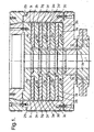
- the prior art die shown in fig. 1 has axis (1) and consists of clamped together discs and shell- or bowlformed parts.
- (2a) and (2b) together form a shell or "bowl”
- (3a) to (3i) are discs fitting into this "bowl”.
- Five components are fed into the die for coextrusion, of which the inlets for two are shown. Apart from the inlet channels all channels for the five components and the common flow of two or more of these components are formed by spaces between the disc- or shell (“bowl")-formed parts, thus the equalisation of each component over the circumference is established by helical grooves (4a) to (4e) which extend generally along a plane perpendicular to the axis (1) and here are seen almost in cross-section. These grooves are formed in the surface of one of a pair of adjacent discs or between the "bowl” and the adjacent disc. (Alternatively there might be grooves in both surfaces facing each other and this is also covered by the present invention).
- the different helical grooves for each component are fed from one, generally circular, common feeding channel. This is all prior art.
- this construction of an extrusion die has the advantage that it allows coextrusion of many components, but has the drawback that these components must have relatively similar rheologies, otherwise the thickness of the individual layers become uneven. This is because the different components are successively joined one after the other, with a relatively long distance between the locations of joining. It should hereby be understood that the high extrusion pressure requires that each disc from which the die is constructed must be relatively thick. However, as already stated, if there is a high viscosity in one component contacting one channel surface and a much lower viscosity In a second component contacting the opposite channel surface, the common flow will soon become irregular.
- the circular die having axis (1) is made from two shell (bowl) - formed parts (5) and (6), two disc-formed parts (7a) and (7b), and in fig. 2b a further disc formed part (7c), three inserts (8a) and (8b) for adjustment of the overflow between the helical channels, and a ring (9) for adjustment of the exit orifice.
- thermoplastic polymer material (A) of a relatively high melt viscosity and two thermoplastic materials (B) and (C) of a lower melt viscosity are fed through separate inlets (10). They divide out in a "labyrinthine" channel system, first branching out to two part flows in channel (11), then continuing as four part flows in channels (12) and as eight part flows in channels (13). (Depending on the dimensions of the die there can of course be formed a larger or smaller number of part flows but in any case an integral power of 2).
- A, B and C proceed towards the common circular exit channel (18) whereby B and C pass internal orifices, (19) and (20) respectively, to join with A.
- the two internal orifices are immediately opposite each other at the same axial location (or there may be an insignificant axial distance between the two).
- the common channel ends in exit orifice (21).
Landscapes
- Engineering & Computer Science (AREA)
- Mechanical Engineering (AREA)
- Manufacturing & Machinery (AREA)
- Life Sciences & Earth Sciences (AREA)
- Food Science & Technology (AREA)
- Chemical & Material Sciences (AREA)
- Polymers & Plastics (AREA)
- Extrusion Moulding Of Plastics Or The Like (AREA)
Claims (38)
- Un procédé de formation d'un film tubulaire par coextrusion d'au moins une matière polymère thermoplastique A avec au moins deux matières polymères thermoplastiques B et C d'un indice d'écoulement à l'état fondu qui est au moins le double de celui de A, B étant appliqué sur l'un et C sur l'autre côté de A, ladite extrusion étant mise en oeuvre au moyen d'une matrice d'extrusion circulaire présentant au moins une entrée (10) pour chaque composé et présentant un passage de sortie commun (18) se terminant en un orifice de sortie circulaire (21) de sorte que la ou chaque entrée est située plus près de l'axe (1) de la matrice circulaire que l'orifice de sortie et que les matières extrudables à l'état fondu s'écoulent vers l'extérieur en direction de l'orifice de sortie, et procédé dans lequel la conformation de chaque écoulement de chaque composé est établie par une disposition de premières parties de matrice (5, 6, 7a, 7b) présentant des surfaces planes ou coniques, parties de matrice qui sont serrées ensemble avec lesdites surfaces présentant des rainures (14) conformées pour constituer des conduits (11, 12, 13, 14) pour l'écoulement de chaque matière polymère de manière à égaliser l'écoulement sur la circonférence de l'orifice de sortie, de sorte qu'au moins l'écoulement de A entre l'entrée ou chaque entrée et la sortie est divisé un certain nombre d'écoulements partiels (14) de forme généralement hélicoïdale au moins à travers une partie de chaque conduit avec un espace (15) prévu pour débordement entre lesdites parties hélicoïdales et lesdits écoulements partiels avec débordements se joignent de manière graduelle en un écoulement circulaire commun caractérisé en ce que la jonction de A avec B (19) est établie au niveau du même emplacement que sa jonction avec C (20) ou à son voisinage immédiat, et en ce que A s'écoule vers l'extérieur par rapport à l'axe de la matrice immédiatement avant qu'il se joigne avec B et C, alors que B et C s'écoulent l'un vers l'autre immédiatement avant la jonction.
- Un procédé selon la revendication 1, caractérisé en ce que lesdits écoulements partiels d'une forme généralement hélicoïdale s'étendent d'une manière généralement plane.
- Un procédé selon la revendication 1, caractérisé en ce que lesdits écoulements partiels d'une forme généralement hélicoïdale s'étendent dans une disposition géométrique comme le long d'une surface conique circulaire, les plans tangents de ladite surface conique délimitant un angle d'au moins 20° par rapport à l'axe de la matrice au moins sur la partie la plus aval de ladite surface.
- Un procédé selon la revendication 3, caractérisé en ce que le dit angle est d'au moins 45°.
- Un procédé selon la revendication 3, caractérisé en ce que ladite surface décrivant l'extension de la forme hélicoïdale est une surface conique droite.
- Un procédé selon la revendication 1, caractérisé en ce que chaque écoulement partiel est formé par une division labyrinthine dans la matrice d'un ou de plusieurs écoulements.
- Un procédé selon la revendication 6, caractérisé en ce que les conduits d'au moins une partie des conduits (11, 12, 13) pour la division labyrinthine sont formés de manière solidaire avec les conduits (14) pour l'écoulement généralement hélicoïdal entre les surfaces planes ou coniques desdites premières parties de matrice par des rainures dans au moins une surface d'une paire de surfaces en contact.
- Un procédé selon la revendication 6, caractérisé en ce que au moins le début de ladite division labyrinthine est établi par l'utilisation de secondes parties de matrice (32, 33, 34)) présentant des surfaces planes ou coniques, les secondes parties de matrice étant serrées ensemble avec les premières parties de matrice, la disposition des conduits pour ledit début de la division labyrinthine étant établie en partie par des rainures (35a, 35b, 36a, 36b) dans des surfaces en contact entre lesdites secondes parties ou entre une seconde partie et une première partie et en partie par des conduits d'interconnexion (37, 38, 39) à travers lesdites secondes et/ou premières parties.
- Un procédé selon la revendication 1, caractérisé en ce que ledit débordement entre les écoulements partiels est réglable par des inserts échangeables (8a) entre de premières parties de matrice ou par une partie d'appareil réglable en position (8b) à l'opposé des rainures.
- Un procédé selon la revendication 1, caractérisé en ce que après jonction des écoulements de différentes matières polymères, l'écoulement commun dans le passage de sortie commun est tourné vers la direction axiale ou se poursuit immédiatement dans cette direction pour s'écouler de manière généralement axiale lorsqu'il atteint l'orifice de sortie.
- Un procédé selon la revendication 1, caractérisé en ce que après jonction de l'écoulement de différentes matières polymères, l'écoulement commun se poursuit droit vers la surface périphérique de la matrice, où est situé l'orifice de sortie, et quitte la sortie sous un angle d'au moins 20 degrés par rapport à l'axe de la matrice, et en ce qu'une surpression réglée est appliquée à l'intérieur du film tubulaire pour établir le diamètre désiré du tube lorsqu'il est tiré vers le bas et solidifié.
- Un procédé selon la revendication 11, caractérisé en ce que ayant quitté l'orifice de sortie, le film tubulaire à l'état fondu rencontre un anneau (22) qui est concentrique à la matrice et dans une relation fixe par rapport à cette dernière, et en ce que le film est tourné sur l'extérieur de l'anneau de sorte que l'angle entre l'axe de la matrice et la direction de déplacement du film est réduit et qu'une force de friction est établie entre l'anneau et le film pour aider à une orientation moléculaire du film, alors que ce dernier est tiré sur l'anneau.
- Un procédé selon la revendication 12, caractérisé en ce que la section transversale de l'anneau est ronde au moins sur la partie de la surface qui vient en contact avec le film.
- Un procédé selon la revendication 12, caractérisé en ce que ledit anneau est refroidi par circulation interne d'un système de refroidissement.
- Un procédé selon la revendication 12, caractérisé en ce que ledit anneau est monté (23) dans le voisinage immédiat de l'orifice de sortie.
- Un procédé selon la revendication 11, caractérisé en ce que au moins un côté de l'orifice de sortie est défini par une lèvre (25) qui est suffisamment souple pour permettre un réglage du trou de l'orifice et en ce que des dispositifs (26) sont prévus pour ce réglage.
- Un procédé selon la revendication 1, caractérisé en ce que, en plus de B et C, au moins une autre matière polymère thermoplastique D présentant un indice d'écoulement à l'état fondu au moins double de celui de A est joint à B ou C à un étage quelconque (30) après l'égalisation de l'écoulement dudit B ou C.
- Un procédé selon la revendication 1, caractérisé en ce que prend place une co-extrusion d'un autre composé E, ayant un indice d'écoulement à l'état fondu égal ou supérieur à celui de A, et en ce que A et E sont soit directement joints l'un avec l'autre avant leur jonction avec les écoulements de B et C, soit sont directement joints l'un avec l'autre au niveau essentiellement du même emplacement (31) que leur jonction avec B et C.
- Un procédé selon la revendication 9, caractérisé en ce que une telle partie d'appareil réglable en position , soit comprend une feuille annulaire souple généralement plate (8b) qui, à ses limites vers l'intérieur (16a) et vers l'extérieur (16c), est fixée à une partie de matrice rigide (7c) faisant partie du système de conduit, soit comprend une plaque annulaire rigide généralement plate qui, à ses limites vers l'intérieur et vers l'extérieur, est articulée par l'intermédiaire d'une feuille souple généralement annulaire à une telle partie de matrice rigide, dans chaque cas avec une rangée circulaire de dispositifs de réglage (44, 45) sur le côté de la feuille ou plaque plate généralement annulaire qui est opposée à l'écoulement.
- Une matrice de co-extrusion circulaire pour co-extruder au moins une matière polymère thermoplastique A avec au moins deux matières polymères thermoplastiques B et C, B étant appliqué sur l'un et C sur l'autre côté de A pour former un film tubulaire, ladite matrice d'extrusion circulaire ayant au moins une entrée (10) pour chaque composé et ayant un conduit de sortie commun (18) se terminant en un orifice de sortie circulaire (21), de sorte que l'entrée ou chaque entrée (10) est située plus près de l'axe (1) de la matrice circulaire que l'orifice de sortie (21) et que les matières extrudables sont dirigées pour s'écouler vers l'extérieur en direction de l'orifice de sortie (21), et dans lequel la conformation de chaque écoulement de chaque composé est établie par une disposition de premières parties de matrice (5, 6, 7, 28, 29) présentant des surfaces planes ou coniques, lesquelles sont serrées ensemble avec les surfaces desdites parties présentant des rainures (14) conformées pour constituer des conduits (11, 12, 13) pour l'écoulement de chaque matière polymère de manière à égaliser l'écoulement sur la circonférence de l'orifice de sortie (21), de sorte qu'au moins l'écoulement de A (12) entre chaque entrée (10) et la sortie (21) est divisé en un certain nombre d'écoulements partiels (13) de forme généralement hélicoïdale avec un espace (15) prévu pour débordement entre lesdits écoulements partiels et adapté pour que lesdits écoulements partiels avec débordements se joignent graduellement en un écoulement circulaire commun, caractérisée en ce que la jonction de A avec B s'établit au niveau du même emplacement que sa jonction avec C ou à son voisinage immédiat, et en ce que les conduits sont adaptés pour faire que A s'écoule vers l'extérieur par rapport à l'axe de la matrice au moins immédiatement avant qu'il se joigne avec B et C, et en ce que les conduits (19, 20) sont adaptés pour faire que B et C s'écoulent l'un vers l'autre immédiatement avant leur jonction avec A.
- Une matrice de co-extrusion selon la revendication 20, caractérisée en ce que lesdits conduits (11, 12) de forme généralement hélicoïdale s'étendent d'une manière généralement plane.
- Une matrice de co-extrusion selon la revendication 20, caractérisée en ce que lesdits conduits (11, 12) de forme généralement hélicoïdale sont formés en une surface conique, les plans tangents desdites surfaces coniques délimitant un angle d'au moins 20° par rapport à l'axe de la matrice au moins sur la partie la plus aval de ladite surface.
- Une matrice de co-extrusion selon la revendication 22, caractérisée en ce que ledit angle est d'au moins 45°.
- Une matrice de co-extrusion selon la revendication 22, caractérisée en ce que la surface conique a une conicité droite.
- Une matrice de co-extrusion selon la revendication 20, caractérisée en ce que chacun des conduits de forme généralement hélicoïdale est conformé en continuation d'un système de division labyrinthine de conduits.
- Une matrice de co-extrusion selon la revendication 25, caractérisée en ce que les conduits d'au moins une partie des conduits pour la division labyrinthine sont formés de manière solidaire avec les conduits de forme généralement hélicoïdale entre les premières parties de matrice serrées ensemble par des rainures dans au moins une surface d'une paire de surfaces en contact.
- Une matrice de co-extrusion selon la revendication 25, caractérisée en ce que au moins la première partie dudit système de division labyrinthine comprend de secondes parties de matrice (32, 33, 34) présentant des surfaces planes ou coniques, les secondes parties de matrice étant serrées ensemble avec lesdites premières parties de matrice, la disposition de conduits pour ladite partie de la division labyrinthine étant établie en partie par des rainures (35, 36) dans des surfaces de contact entre lesdites secondes parties ou entre une seconde partie (34) et une première partie (5) et en partie par des conduits d'interconnexion (37, 38, 39) à travers lesdites secondes et/ou premières parties.
- Une matrice de co-extrusion selon la revendication 20, caractérisée en ce que le débordement entre les écoulements partiels est rendu réglable par des inserts échangeables (8a) dans la matrice ou par une partie d'appareil réglable en position (8b) à l'opposé des rainures.
- Une matrice de co-extrusion selon la revendication 20, caractérisée en ce que , à l'aval de l'emplacement pour jonction des écoulements de différentes matières polymères, le conduit pour l'écoulement commun (18) est tourné vers la direction axiale, ou en ce que ce conduit est généralement axial sur tout le trajet depuis ledit emplacement, pour diriger l'écoulement de manière généralement axiale lorsqu'il atteint l'orifice de sortie (21).
- Une matrice de co-extrusion selon la revendication 20, caractérisée en ce que , à l'aval de l'emplacement pour jonction des écoulements de différentes matières polymères, le conduit pour l'écoulement commun (18) se poursuit vers la surface périphérique de la matrice, où est situé l'orifice de sortie (21) et, au niveau de l'orifice de sortie, ledit conduit pour l'écoulement commun (18) délimite un angle d'au moins 20° par rapport à l'axe de la matrice, et en ce que des moyens sont prévus pour tirer vers le bas le film tubulaire extrudé tout en appliquant une surpression intérieure régulée pour établir le diamètre désiré.
- Une matrice de co-extrusion selon la revendication 30, caractérisée par le fait de comprendre un anneau (22) qui est concentrique avec la matrice et en relation fixe par rapport à cette dernière à un niveau tel que le film tubulaire puisse être tourné sur la surface de cet anneau par des dispositifs tirant le film généralement dans la direction axiale.
- Une matrice de co-extrusion selon la revendication 31, caractérisée en ce que la section transversale de l'anneau (22) est ronde au moins sur la partie de la surface qui est adaptée pour venir en contact avec le film.
- Une matrice de co-extrusion selon la revendication 31, caractérisée par des moyens (24) pour refroidir ledit anneau par circulation interne d'un milieu de refroidissement.
- Une matrice de co-extrusion selon la revendication 31, caractérisée en ce que ledit anneau est monté au voisinage immédiat de l'orifice de sortie (21).
- Une matrice de co-extrusion selon la revendication 30, caractérisée en ce que au moins un côté de l'orifice de sortie est constitué par une lèvre (25) qui est suffisamment souple pour permettre le réglage du trou et en ce que la matrice comprend des dispositifs pour ce réglage.
- Une matrice de co-extrusion selon la revendication 20, caractérisée en ce que en plus du système total de conduits pour B et C, on prévoit un système de conduits (10, 11, 30) pour co-extruder au moins une autre matière polymère thermoplastique D, lesdits conduits se terminant en un orifice interne (30) pour jonction de D avec B ou C à l'aval des conduits qui égalisent l'écoulement dudit B ou C.
- Une matrice de co-extrusion selon la revendication 36, caractérisée en ce que l'emplacement pour jonction de D avec B ou C est essentiellement le même que l'emplacement de la jonction de A avec B et C.
- Une matrice d'extrusion circulaire selon la revendication 28, caractérisée en ce que une telle partie d'appareil réglable en position, soit comprend une feuille annulaire souple généralement plate (8b) qui, à ses limites vers l'intérieur (16a) et vers l'extérieur (16c), est fixée à une partie de matrice rigide faisant partie du système de conduits, soit comprend une plaque annulaire rigide généralement plate qui, à ses limites vers l'intérieur et vers l'extérieur, est articulée par l'intermédiaire d'une feuille souple généralement annulaire à une telle partie de matrice rigide, dans chaque cas avec une rangée circulaire de dispositifs de réglage (45, 46) sur le côté de la feuille ou plaque plate généralement annulaire qui est opposée à l'écoulement.
Priority Applications (1)
| Application Number | Priority Date | Filing Date | Title |
|---|---|---|---|
| EP01983566A EP1345749B1 (fr) | 2000-12-22 | 2001-10-15 | Procedes et appareil d'extrusion d'un film tubulaire |
Applications Claiming Priority (6)
| Application Number | Priority Date | Filing Date | Title |
|---|---|---|---|
| GB0031720 | 2000-12-22 | ||
| GBGB0031720.6A GB0031720D0 (en) | 2000-12-22 | 2000-12-22 | Method and apparatus for joining sheet or ribbon formed flows in a coextrusion process |
| PCT/EP2001/004885 WO2001078966A1 (fr) | 2000-04-13 | 2001-04-11 | Procede et appareil permettant d'unir des flux constitues en feuilles ou en rubans au cours d'un procede de coextrusion |
| WOPCT/EP01/04885 | 2001-04-11 | ||
| PCT/EP2001/012430 WO2002051617A1 (fr) | 2000-12-22 | 2001-10-15 | Procédés et appareil d'extrusion d'un film tubulaire |
| EP01983566A EP1345749B1 (fr) | 2000-12-22 | 2001-10-15 | Procedes et appareil d'extrusion d'un film tubulaire |
Publications (2)
| Publication Number | Publication Date |
|---|---|
| EP1345749A1 EP1345749A1 (fr) | 2003-09-24 |
| EP1345749B1 true EP1345749B1 (fr) | 2005-08-17 |
Family
ID=56290208
Family Applications (1)
| Application Number | Title | Priority Date | Filing Date |
|---|---|---|---|
| EP01983566A Expired - Lifetime EP1345749B1 (fr) | 2000-12-22 | 2001-10-15 | Procedes et appareil d'extrusion d'un film tubulaire |
Country Status (1)
| Country | Link |
|---|---|
| EP (1) | EP1345749B1 (fr) |
-
2001
- 2001-10-15 EP EP01983566A patent/EP1345749B1/fr not_active Expired - Lifetime
Also Published As
| Publication number | Publication date |
|---|---|
| EP1345749A1 (fr) | 2003-09-24 |
Similar Documents
| Publication | Publication Date | Title |
|---|---|---|
| US20040070105A1 (en) | Methods and apparatus for extruding a tubular film | |
| US5069612A (en) | Modular tubular extrusion head | |
| CA2536367C (fr) | Machine de formage par moulage de film multicouches et procede associe | |
| US7811073B2 (en) | Blow head for producing blown tubular film | |
| EP1464467A2 (fr) | Extrudeuse avec une filière circulaire pour la coextrusion | |
| US6787092B2 (en) | Pipe extrusion die for multi-layer pipe | |
| JP2000511482A (ja) | 吹込み成形フィルムを押出し成形するときの溶融体の流れを規則的に分割する法 | |
| EP2047963B1 (fr) | Appareil pour l'extrusion de film | |
| AU588484B2 (en) | Modular extrusion head, method, intermediate product and product | |
| US4895744A (en) | Method of making a multi-layer parison | |
| US6942606B2 (en) | Roll having multiple fluid flow channels for use in producing and processing sheet material | |
| US3784339A (en) | Disk extruder | |
| EP1345749B1 (fr) | Procedes et appareil d'extrusion d'un film tubulaire | |
| US5019433A (en) | Multi-layer molten plastic body | |
| CN111037871A (zh) | 用于制造多层管薄膜的吹头和方法 | |
| KR100192018B1 (ko) | 열가소성 수지제의 벌집구조의 단면재, 단면재의 압출헤드 및 그 제조방법 | |
| AU2002215035A1 (en) | Methods and apparatus for extruding a tubular film | |
| WO2003033238A1 (fr) | Repartition peripherique amelioree dans une filiere d'extrusion circulaire | |
| JP2512668B2 (ja) | モジュ―ル式管状押出しヘッド | |
| US4495022A (en) | Extrusion method and apparatus | |
| US5827468A (en) | Turning calibration apparatus and process | |
| CN100396470C (zh) | 管状热塑性薄膜的纵向定向 | |
| HK1066759A (en) | Methods and apparatus for extruding a tubular film | |
| CA2204548C (fr) | Systeme a levres de filieres chauffees | |
| EP0626246A1 (fr) | Tête d'extrusion pour paraisons multicouches en combinaisons de matériaux instables |
Legal Events
| Date | Code | Title | Description |
|---|---|---|---|
| PUAI | Public reference made under article 153(3) epc to a published international application that has entered the european phase |
Free format text: ORIGINAL CODE: 0009012 |
|
| 17P | Request for examination filed |
Effective date: 20030721 |
|
| AK | Designated contracting states |
Kind code of ref document: A1 Designated state(s): AT BE CH CY DE DK ES FI FR GB GR IE IT LI LU MC NL PT SE TR |
|
| AX | Request for extension of the european patent |
Extension state: AL LT LV MK RO SI |
|
| GRAP | Despatch of communication of intention to grant a patent |
Free format text: ORIGINAL CODE: EPIDOSNIGR1 |
|
| GRAS | Grant fee paid |
Free format text: ORIGINAL CODE: EPIDOSNIGR3 |
|
| GRAA | (expected) grant |
Free format text: ORIGINAL CODE: 0009210 |
|
| AK | Designated contracting states |
Kind code of ref document: B1 Designated state(s): AT BE CH CY DE DK ES FI FR GB GR IE IT LI LU MC NL PT SE TR |
|
| PG25 | Lapsed in a contracting state [announced via postgrant information from national office to epo] |
Ref country code: BE Free format text: LAPSE BECAUSE OF FAILURE TO SUBMIT A TRANSLATION OF THE DESCRIPTION OR TO PAY THE FEE WITHIN THE PRESCRIBED TIME-LIMIT Effective date: 20050817 Ref country code: AT Free format text: LAPSE BECAUSE OF FAILURE TO SUBMIT A TRANSLATION OF THE DESCRIPTION OR TO PAY THE FEE WITHIN THE PRESCRIBED TIME-LIMIT Effective date: 20050817 Ref country code: NL Free format text: LAPSE BECAUSE OF FAILURE TO SUBMIT A TRANSLATION OF THE DESCRIPTION OR TO PAY THE FEE WITHIN THE PRESCRIBED TIME-LIMIT Effective date: 20050817 Ref country code: TR Free format text: LAPSE BECAUSE OF FAILURE TO SUBMIT A TRANSLATION OF THE DESCRIPTION OR TO PAY THE FEE WITHIN THE PRESCRIBED TIME-LIMIT Effective date: 20050817 Ref country code: CH Free format text: LAPSE BECAUSE OF FAILURE TO SUBMIT A TRANSLATION OF THE DESCRIPTION OR TO PAY THE FEE WITHIN THE PRESCRIBED TIME-LIMIT Effective date: 20050817 Ref country code: FI Free format text: LAPSE BECAUSE OF FAILURE TO SUBMIT A TRANSLATION OF THE DESCRIPTION OR TO PAY THE FEE WITHIN THE PRESCRIBED TIME-LIMIT Effective date: 20050817 Ref country code: LI Free format text: LAPSE BECAUSE OF FAILURE TO SUBMIT A TRANSLATION OF THE DESCRIPTION OR TO PAY THE FEE WITHIN THE PRESCRIBED TIME-LIMIT Effective date: 20050817 Ref country code: IT Free format text: LAPSE BECAUSE OF FAILURE TO SUBMIT A TRANSLATION OF THE DESCRIPTION OR TO PAY THE FEE WITHIN THE PRESCRIBED TIME-LIMIT;WARNING: LAPSES OF ITALIAN PATENTS WITH EFFECTIVE DATE BEFORE 2007 MAY HAVE OCCURRED AT ANY TIME BEFORE 2007. THE CORRECT EFFECTIVE DATE MAY BE DIFFERENT FROM THE ONE RECORDED. Effective date: 20050817 |
|
| REG | Reference to a national code |
Ref country code: GB Ref legal event code: FG4D |
|
| REG | Reference to a national code |
Ref country code: CH Ref legal event code: EP |
|
| REG | Reference to a national code |
Ref country code: IE Ref legal event code: FG4D |
|
| REF | Corresponds to: |
Ref document number: 60112794 Country of ref document: DE Date of ref document: 20050922 Kind code of ref document: P |
|
| PG25 | Lapsed in a contracting state [announced via postgrant information from national office to epo] |
Ref country code: CY Free format text: LAPSE BECAUSE OF FAILURE TO SUBMIT A TRANSLATION OF THE DESCRIPTION OR TO PAY THE FEE WITHIN THE PRESCRIBED TIME-LIMIT Effective date: 20051015 |
|
| PG25 | Lapsed in a contracting state [announced via postgrant information from national office to epo] |
Ref country code: IE Free format text: LAPSE BECAUSE OF NON-PAYMENT OF DUE FEES Effective date: 20051017 |
|
| PG25 | Lapsed in a contracting state [announced via postgrant information from national office to epo] |
Ref country code: LU Free format text: LAPSE BECAUSE OF NON-PAYMENT OF DUE FEES Effective date: 20051031 Ref country code: MC Free format text: LAPSE BECAUSE OF NON-PAYMENT OF DUE FEES Effective date: 20051031 |
|
| PG25 | Lapsed in a contracting state [announced via postgrant information from national office to epo] |
Ref country code: GB Free format text: LAPSE BECAUSE OF NON-PAYMENT OF DUE FEES Effective date: 20051117 Ref country code: SE Free format text: LAPSE BECAUSE OF FAILURE TO SUBMIT A TRANSLATION OF THE DESCRIPTION OR TO PAY THE FEE WITHIN THE PRESCRIBED TIME-LIMIT Effective date: 20051117 Ref country code: GR Free format text: LAPSE BECAUSE OF FAILURE TO SUBMIT A TRANSLATION OF THE DESCRIPTION OR TO PAY THE FEE WITHIN THE PRESCRIBED TIME-LIMIT Effective date: 20051117 Ref country code: DK Free format text: LAPSE BECAUSE OF FAILURE TO SUBMIT A TRANSLATION OF THE DESCRIPTION OR TO PAY THE FEE WITHIN THE PRESCRIBED TIME-LIMIT Effective date: 20051117 |
|
| PG25 | Lapsed in a contracting state [announced via postgrant information from national office to epo] |
Ref country code: DE Free format text: LAPSE BECAUSE OF FAILURE TO SUBMIT A TRANSLATION OF THE DESCRIPTION OR TO PAY THE FEE WITHIN THE PRESCRIBED TIME-LIMIT Effective date: 20051118 |
|
| PG25 | Lapsed in a contracting state [announced via postgrant information from national office to epo] |
Ref country code: ES Free format text: LAPSE BECAUSE OF FAILURE TO SUBMIT A TRANSLATION OF THE DESCRIPTION OR TO PAY THE FEE WITHIN THE PRESCRIBED TIME-LIMIT Effective date: 20051128 |
|
| PG25 | Lapsed in a contracting state [announced via postgrant information from national office to epo] |
Ref country code: PT Free format text: LAPSE BECAUSE OF FAILURE TO SUBMIT A TRANSLATION OF THE DESCRIPTION OR TO PAY THE FEE WITHIN THE PRESCRIBED TIME-LIMIT Effective date: 20060117 |
|
| NLV1 | Nl: lapsed or annulled due to failure to fulfill the requirements of art. 29p and 29m of the patents act | ||
| REG | Reference to a national code |
Ref country code: CH Ref legal event code: PL |
|
| PLBE | No opposition filed within time limit |
Free format text: ORIGINAL CODE: 0009261 |
|
| STAA | Information on the status of an ep patent application or granted ep patent |
Free format text: STATUS: NO OPPOSITION FILED WITHIN TIME LIMIT |
|
| 26N | No opposition filed |
Effective date: 20060518 |
|
| GBPC | Gb: european patent ceased through non-payment of renewal fee |
Effective date: 20051117 |
|
| REG | Reference to a national code |
Ref country code: IE Ref legal event code: MM4A |
|
| PG25 | Lapsed in a contracting state [announced via postgrant information from national office to epo] |
Ref country code: FR Free format text: LAPSE BECAUSE OF FAILURE TO SUBMIT A TRANSLATION OF THE DESCRIPTION OR TO PAY THE FEE WITHIN THE PRESCRIBED TIME-LIMIT Effective date: 20060818 |
|
| EN | Fr: translation not filed | ||
| PG25 | Lapsed in a contracting state [announced via postgrant information from national office to epo] |
Ref country code: FR Free format text: LAPSE BECAUSE OF FAILURE TO SUBMIT A TRANSLATION OF THE DESCRIPTION OR TO PAY THE FEE WITHIN THE PRESCRIBED TIME-LIMIT Effective date: 20051031 |
|
| PG25 | Lapsed in a contracting state [announced via postgrant information from national office to epo] |
Ref country code: FR Free format text: LAPSE BECAUSE OF FAILURE TO SUBMIT A TRANSLATION OF THE DESCRIPTION OR TO PAY THE FEE WITHIN THE PRESCRIBED TIME-LIMIT Effective date: 20050817 |