EP1347122A1 - Packer und Verfahren zum Einbringen des Packers in ein Gebäudeteil - Google Patents
Packer und Verfahren zum Einbringen des Packers in ein Gebäudeteil Download PDFInfo
- Publication number
- EP1347122A1 EP1347122A1 EP02005199A EP02005199A EP1347122A1 EP 1347122 A1 EP1347122 A1 EP 1347122A1 EP 02005199 A EP02005199 A EP 02005199A EP 02005199 A EP02005199 A EP 02005199A EP 1347122 A1 EP1347122 A1 EP 1347122A1
- Authority
- EP
- European Patent Office
- Prior art keywords
- packer
- hole
- sealing lip
- building
- fastening
- Prior art date
- Legal status (The legal status is an assumption and is not a legal conclusion. Google has not performed a legal analysis and makes no representation as to the accuracy of the status listed.)
- Granted
Links
- 238000000034 method Methods 0.000 title claims abstract description 15
- 238000010276 construction Methods 0.000 title 1
- 239000000463 material Substances 0.000 claims abstract description 64
- 239000007788 liquid Substances 0.000 claims abstract description 13
- 239000006260 foam Substances 0.000 claims abstract description 6
- 239000004566 building material Substances 0.000 claims abstract description 5
- 239000007787 solid Substances 0.000 claims abstract description 5
- 229910052500 inorganic mineral Inorganic materials 0.000 claims abstract description 4
- 239000011707 mineral Substances 0.000 claims abstract description 4
- 238000007789 sealing Methods 0.000 claims description 40
- 239000011324 bead Substances 0.000 claims description 10
- 230000008878 coupling Effects 0.000 claims description 10
- 238000010168 coupling process Methods 0.000 claims description 10
- 238000005859 coupling reaction Methods 0.000 claims description 10
- 238000003780 insertion Methods 0.000 claims description 9
- 230000037431 insertion Effects 0.000 claims description 9
- 230000002401 inhibitory effect Effects 0.000 claims description 2
- 230000008569 process Effects 0.000 abstract description 3
- 238000002347 injection Methods 0.000 description 8
- 239000007924 injection Substances 0.000 description 8
- 238000004873 anchoring Methods 0.000 description 6
- 238000005187 foaming Methods 0.000 description 6
- 230000000694 effects Effects 0.000 description 5
- 238000007711 solidification Methods 0.000 description 5
- 230000008023 solidification Effects 0.000 description 5
- 230000035515 penetration Effects 0.000 description 4
- 230000004888 barrier function Effects 0.000 description 3
- 230000003993 interaction Effects 0.000 description 2
- 230000009471 action Effects 0.000 description 1
- 230000001070 adhesive effect Effects 0.000 description 1
- QVGXLLKOCUKJST-UHFFFAOYSA-N atomic oxygen Chemical compound [O] QVGXLLKOCUKJST-UHFFFAOYSA-N 0.000 description 1
- 230000008859 change Effects 0.000 description 1
- 230000001419 dependent effect Effects 0.000 description 1
- 239000013013 elastic material Substances 0.000 description 1
- 230000002349 favourable effect Effects 0.000 description 1
- -1 masonry Substances 0.000 description 1
- 239000002184 metal Substances 0.000 description 1
- 229910052760 oxygen Inorganic materials 0.000 description 1
- 239000001301 oxygen Substances 0.000 description 1
- 238000009418 renovation Methods 0.000 description 1
- 230000000630 rising effect Effects 0.000 description 1
- 230000006641 stabilisation Effects 0.000 description 1
- 238000011105 stabilization Methods 0.000 description 1
- 239000002023 wood Substances 0.000 description 1
Images

Classifications
-
- E—FIXED CONSTRUCTIONS
- E04—BUILDING
- E04G—SCAFFOLDING; FORMS; SHUTTERING; BUILDING IMPLEMENTS OR AIDS, OR THEIR USE; HANDLING BUILDING MATERIALS ON THE SITE; REPAIRING, BREAKING-UP OR OTHER WORK ON EXISTING BUILDINGS
- E04G23/00—Working measures on existing buildings
- E04G23/02—Repairing, e.g. filling cracks; Restoring; Altering; Enlarging
- E04G23/0203—Arrangements for filling cracks or cavities in building constructions
- E04G23/0211—Arrangements for filling cracks or cavities in building constructions using injection
Definitions
- the present invention relates to a packer and a method for Inserting this packer in a building part.
- packers When injecting liquid media into building parts made of solid mineral Building materials, such as masonry, concrete and the like (but not made of wood or metal) so-called packers are used. These are in the Substantial tubular devices with an inner tube passage. These Packers are installed in a hole in the building part and serve to inject a liquid medium into the building part.
- Injection medium may be a liquid for the restoration of masonry, for building barrier layers against rising moisture, for Backfilling cavities and sealing cracks and the like act. Regardless of the exact function of the injection medium is the The task of the packer in this is to be able to inject the medium into To provide liquid state in the building part, including on the packer a Line is connected. In this case, relatively high pressures may be necessary, so that the anchoring of the packer in the building part an essential role plays. Often the anchored packers are in the hole after use leave.
- the invention is based on the technical problem of providing an improved packer and to provide a method for introducing the packer into the building part.
- the invention relates firstly to a method for introducing a packer in a building part of solid mineral building material, in which the packer in one of an outer surface of the building part directed inwards into the building part Hole is inserted between an outer surface of the packer and a Inner surface of the hole, a liquid fastening material is introduced and the fastening material solidifies, so that the packer of the solidified Mounting material is held in the hole.
- the invention relates to a designed for this method Packer, comprising: a substantially tubular inner part, which is designed after insertion of the packer in the hole in the hole to be arranged, and from between an outer surface of the inner part and the Inner surface of the hole introduced mounting material held in the hole to be, and a subsequent to the inner part of the outer part, the is designed after insertion of the packer in the hole outside the Hole to be arranged, and a sealing lip for inhibiting a Vordringens the fastening material, which at the inner part at a distance from the Outer part is arranged and runs around the circumference of the inner part.
- the invention also relates to a set of such Packer and a liquid fastening material that after insertion into can solidify the hole.
- the invention uses for anchoring the packer in the building part liquid to be introduced fastening material, which is between the packer and solidified the inner wall of the hole.
- This can be a one-component Act material that solidifies, for example by contact with oxygen, or to a multi-component material, which after mixing the Components solidified.
- Particularly preferred are in the invention foam-forming fastening materials which foam after introduction and then solidify, for example PUR foam systems.
- the packer is in this new form of attachment in the building part so far adjusted, as he was at his inner part at a certain distance from his Outer part has a sealing lip, which further penetration of the Fixing material in the hole during insertion of the Mounting material or thereafter - for example, during foaming - inhibits or stops.
- the material of the building part such as brittle masonry, not strong and not punctually loaded.
- This distinguishes the invention advantageous from conventional packers in which, for example, pods elastic material can be compressed within the hole to pass through Press against the inner walls of the hole to achieve a clamping action.
- This clamping effect takes place only between a comparatively small Surface area of the sleeve and the hole inner wall instead of and therefore loads the Masonry or other material of the building part unevenly. If that Material is brittle, the attachment effect is insufficient.
- the mounting material does not necessarily have to be one solidify the actual solid. It may suffice that it is its viscosity greatly increased. Specifically, the requirements for strength and Resilience of the fastening material after solidification of the strong Material of the building part and of the expected injection pressure at the dependent on the later use of the packer.
- the described sealing lip of the packer not only serves to Mounting material between the packer and the surrounding inner edge of the To keep holes.
- the sealing lip further improves the anchoring of the packer in the fastening material after solidification.
- This inner section may be the just mentioned sealing lip.
- the attachment material may preferably be cannulated into the hole be introduced, which is in the space between packer and Hole inner wall can be inserted or at least at the outer access let introduce.
- the packer is further provided with a closure plate when inserting the packer in the hole on the outer wall of the building part, so to speak the outer edge of the hole to the plant comes and thus closes the gap to the outside. This degree Of course, it does not have to be tight in the true sense of the word. Similar to the already mentioned sealing lip it is sufficient that a flow out of the Fixing material is at least significantly inhibited.
- the end plate may preferably provide ways to perform the Mounting material, in particular the cannula, have. It can be for example, to act on thin sites that are pierced with the cannula, or to relatively small holes, which is nothing to the described termination effect change essential.
- the sealing lip described has preferably a distance from the End plate or, if no end plate is present, to the limit between outer part and inner part, which is at least twice, especially preferably at least three times the outer diameter of the mecanicteils in this area between the sealing lip and outer part.
- the sealing lip is provided in duplicate, wherein between the two single sealing lips is an axial distance, compared to the Distance to the outer part of the packer is relatively small.
- the sealing lip has the described centering function, by the inner part approximately in the hole center holds. In case of multiple execution it can over the centering out the packer also something against a tilt and thus keep a certain Exercise centering function over the longitudinal extent of the inner part. It however, does not significantly affect the precision of this centering.
- a favorable dimensioning for the sealing lip height is 20% of that at this point in the remaining external diameter of the packer or more.
- the sealing lip or the sealing lips then have an outer diameter of at least 1.2 times the outside diameter occurring in adjacent areas the packer.
- a bead (or several beads) may be provided, however has a smaller outer radius than the sealing lip and thus not up to the Inner wall of the hole comes up.
- This bead can improve the Anchoring of the packer in the mounting material after its solidification serve and thus support the function of the sealing lip (s). It was also empirically found that this bead the distribution of the fastening material between the outer wall of the packer and the inner wall of the hole can.
- the bead preferably, but not necessarily, runs around the The circumference of the packer inner part around. At only one part of the circumference occurring bead is the concept of the outer radius only on this part Respectively.
- the invention provides, the inner tube passage of the packer possible Run without restriction, so in particular no valve in the packer provided. This can be an effective injection and in particular a more effective Pressure build-up within the hole can be effected. Together with the to Restructuring building materials on the one hand gentle and on the other hand very effective Anchoring the packer thus results in significant advantages in use.
- the invention provides a further preferred embodiment Coupling on the outer part of the packer, which is for a detachable Snap coupling is provided by a line to be connected.
- this coupling to a common connection system of Be adapted to garden hoses.
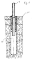
- the packer 1 shown in the figures has an inner part 2 and a Outside part 3 on.
- the inner part 2 and the outer part 3 are perpendicular by a to the drawn in the figures longitudinal axis of the packer 1 extending and the packer 1 surrounding its periphery annular end plate 4th separated.
- the end plate 4 has two parallel to the longitudinal axis small openings 5 on.
- the inner part 2 and the outer part 3 of the packer are otherwise substantially tubular and contain an inner tube passage 6, the, of a light Diameter enlargement approximately in the area of the end plate 4 to the side of the Inside part 2 down apart, smooth cylindrical shape and no further Has constrictions and the like.
- connection for a common Snap coupling of a hose coupling system provided at the outer end of the outer part 3 . It can for example, one of the common in the garden area Snap coupling systems for tubing act. Depending on the requirements Tube diameter and pressure resistance can of course be different Connection variants can be selected, such as screw-on connections 7 or simple conical tapers for pushing on a hose end.
- the inner part 2 of the packer 1 has a relative to its overall length large distance from the end plate 4 two at a small axial distance mutually extending sealing lips 8, which is a slightly smaller Outside diameter than the end plate 4.
- a further bead-like increase in diameter provided, namely a bead 9 to improve the distribution of the Mounting material and for anchoring the packer in the Mounting hardware.
- the outer diameter of the bead 9 is larger than that remaining outer diameter of the inner part 2, but smaller than that of the sealing lips 8th.
- the described packer 1 is a PE injection molded part, but could also be made consist of a different material and be made in other ways.
- the packer 1 When used, the packer 1 by hand and with little effort inserted into a hole 10 shown in Figure 1, wherein the sealing lips. 8 ideally under slight pressure in contact with the inner wall of the borehole 10 or, depending on the tolerances, some of the inner walls of the Wellbore 10 are spaced.
- the outer diameter of the end plate 4 is in any case larger than the inner diameter of the borehole 10, so that the End plate with its outer edge at the input edge of the borehole 10, So on the outside of the building part, in which the borehole 10 is mounted and which is shown in Figure 1, comes to rest.
- the Through openings 5 at least one of the two, in conjunction with the borehole 10.
- a PU liquid through one of the two passage openings 5 of the end plate 4 in the borehole 10th injected and foams up there under strong expansion.
- Advantageous is the Use of a metering gun for introducing the PUR liquid, the one carries appropriate cannula.
- the PUR material is in Figure 1 in small points represented and designated 11. It can be seen that the PUR material 11 when foaming around the circumference of the inner part 2 of the packer 1 distributed and while up to the end plate 4 facing sealing lip 8 penetrates. The Both sealing lips 8 hold the PUR material 11 from further penetration in the hole 10 from.
- the sealing lips 8 of the Drill hole inside wall can cause a certain penetration into the Interspace between the two sealing lips 8 or even to a slight further penetration, but this is negligible.
- FIG. 1 also shows symbolically represented cracks in the material of FIG Building part, in which the PUR material 11 also penetrates.
- the PUR material 11 is still relatively low viscous during foaming and thus can be well in fine bumps and cracks penetrate easily along the inner part 2 distribute the packer 1.
- the PUR material solidifies 11 and thus holds by interaction with the outer wall of the inner part 2 of the Packers 1, in particular with the bead 9 and the sealing lips 8, and further by Interaction with the inner wall of the borehole 10, and in particular their Projections, depressions and cracks, the packer 1 very firmly in the borehole 10.
- This may be a mechanical barrier effect in the sense of Add form-fitting and an adhesive effect.
- the PUR material exercises no large radial forces on the inner wall of the borehole 10, so that the building part by this inventive form of attachment no further is damaged.
- the solidified PUR material 11 holds the packer 1 in injecting the Injection medium not only fixed in the hole 10, but seals the Borehole 10, apart from the inner tube channel 6, effective outwards. Thus, the desired pressure build-up can be achieved.
- a medium for the treatment of the building part are injected can.
- This injection medium passes through the inner tube channel 6 of the packer. 1 and thus penetrates into the not detected by the packer 1 inner end of the Drill hole 10. From this area, the injection medium must be through the indicated in Figure 1 cracks or through the material of the building part even in the material distribute and unfold its effect. It can be to build a barrier against moisture or mechanical Stabilization or the like act.
- the outer part 3 of the packer 1 can by the way in the vicinity of the end plate 4 be equipped with a predetermined breaking point, not shown in the figures, so that it can be broken off after its use, the inner part 2 with the end plate 4 remains in the building part. But it can also be one another possibility of removing the outer part 3 may be provided, such as a Plug or screw connection. In the example shown, the Outer part 3 be frayed after use of the packer 1.
- the hose system can have a distributor coupling, so that several packers of illustrated design of individual hose pieces with this distributor coupling and can be connected to a single supply terminal.
- the figures show the exemplary packer 1 to scale. He actually has a length of about 10 - 20 cm.
- the inner diameter of the inner pipe channel 6 and therefore the outer diameter should be adapted to the dimensions of the used hose system and the used snap coupling be adjusted.
- the dimensions of the sealing lips 8 should turn preferably at least 20% larger than the remaining outside diameter of the Inner part 2.
- the distance between the sealing lips 8 and the End plate 4 preferably more than three times the outer diameter of the inner part amount.
- the outer part 3 of the packer 1 can be handled may be relatively short, but may also be briefly stated for practical reasons become. He should from the end plate 4 to the extreme end preferably at least 0.5-2 cm and preferably not more than 6-15 cm long his.
Landscapes
- Engineering & Computer Science (AREA)
- Architecture (AREA)
- Chemical & Material Sciences (AREA)
- Chemical Kinetics & Catalysis (AREA)
- Electrochemistry (AREA)
- Mechanical Engineering (AREA)
- Civil Engineering (AREA)
- Structural Engineering (AREA)
- Consolidation Of Soil By Introduction Of Solidifying Substances Into Soil (AREA)
- Conveying And Assembling Of Building Elements In Situ (AREA)
Abstract
Description
- Figur 1
- zeigt einen Schnitt durch einen erfindungsgemäßen Packer entlang seiner Längsachse, der in ein Loch in einem Gebäudeteil eingesetzt ist.
- Figur 2
- zeigt den Packer aus Figur 1 in Seitenansicht.
- Figur 3
- zeigt den Packer in einer Figur 1 entsprechenden Schnittdarstellung, jedoch nur den Packer selbst.
- Figur 4
- zeigt eine Draufsicht auf den Packer, die einer Ansicht entlang der Längsrichtung entsprechend Figur 2 von oben entspricht.
Claims (14)
- Verfahren zum Befestigen eines Packers (1) in einem Gebäudeteil aus festem mineralischen Baustoff,
bei dem der Packer (1) in ein von einer Außenfläche des Gebäudeteils nach innen in das Gebäudeteil gerichtetes Loch (10) eingeschoben wird, zwischen eine Außenfläche des Packers (1) und eine Innenfläche des Lochs (10) ein flüssiges Befestigungsmaterial (11) eingebracht wird, und sich das Befestigungsmaterial (11) verfestigt, so dass der Packer (1) von dem verfestigten Befestigungsmaterial (11) in dem Loch (10) gehalten wird. - Verfahren nach Anspruch 1, bei dem das Befestigungsmaterial (11) ein nach Einbringen in das Loch (10) aufschäumendes und sich als Schaum verfestigendes Material ist.
- Verfahren nach Anspruch 1 oder 2, bei dem das Befestigungsmaterial (11) mit einer Kanüle zwischen die Außenfläche des Packers (1) und die Innenfläche des Lochs (10) eingebracht wird.
- Verfahren nach einem der vorstehenden Ansprüche, bei dem der Packer eine Abschlussplatte (4) aufweist, die nach dem Einschieben des Packers (1) in das Loch (10) an der Außenfläche des Gebäudeteils zur Anlage kommt und das Loch (10) im Wesentlichen nach außen abschließt, wobei das Befestigungsmaterial (11) durch die Abschlussplatte (4) hindurch zwischen die Außenfläche des Packers (1) und die Innenfläche des Lochs (10) eingebracht wird.
- Verfahren nach einem der vorstehenden Ansprüche, bei dem der Packer (1) in dem Loch (10) durch einen an den Lochinnenquerschnitt angepassten Abschnitt (8) des Packers (1) zumindest stellenweise zentriert wird.
- Packer (1), der für ein Verfahren nach einem der vorstehenden Ansprüche ausgelegt ist und aufweist:einen im Wesentlichen rohrförmigen Innenteil (2), der dazu ausgelegt ist, nach dem Einschieben des Packers (1) in das Loch (10) in dem Loch (10) angeordnet zu sein und von zwischen eine Außenfläche des Innenteils (2) und die Innenfläche des Lochs (10) eingebrachtem Befestigungsmaterial (11) in dem Loch (10) gehalten zu werden,und einen an dem Innenteil (2) anschließenden Außenteil (3), der dazu ausgelegt ist, nach dem Einschieben des Packers (1) in das Loch (10) außerhalb des Lochs (10) angeordnet zu sein,und eine Dichtlippe (8) zum Hemmen eines Vordringens des Befestigungsmaterials (11), die an dem Innenteil (2) in einem Abstand von dem Außenteil (3) angeordnet ist und um den Umfang des Innenteils (2) läuft.
- Packer (1) nach Anspruch 6, bei dem der Abstand zwischen der Dichtlippe (8) und dem Außenteil (3) zumindest das Doppelte des Außendurchmessers des Innenteils (2) in dem Bereich dieses Abstandes beträgt.
- Packer (1) nach Anspruch 6 oder 7, bei dem die Dichtlippe (8) doppelt und mit einem axialen Versatz zwischen den beiden Dichtlippen (8) vorgesehen ist.
- Packer (1) nach einem der Ansprüche 6 bis 8, bei dem der Außendurchmesser der Dichtlippe (8) zumindest das 1,2-fache des Außendurchmessers des Innenteils (2) in dem Bereich zwischen dem Außenteil (3) und der Dichtlippe (8) beträgt.
- Packer (1) nach einem der Ansprüche 6 bis 9, der eine Abschlussplatte (4) aufweist, die nach dem Einschieben des Packers (1) in das Loch (10) an der Außenfläche des Gebäudeteils zur Anlage kommt und das Loch (10) im Wesentlichen nach außen abschließt.
- Packer (1) nach Anspruch 10, bei dem zwischen der Abschlussplatte (4) und der Dichtlippe (8) ein Wulst (9) mit einem gegenüber der Dichtlippe (8) geringerem Außenradius vorgesehen ist.
- Packer (1) nach einem der Ansprüche 6 bis 11 mit einem ventilfreien Innenrohrdurchgang (6) durch den Innenteil (2) und den Außenteil (3) des Packers (1).
- Packer (1) nach einem der Ansprüche 6 bis 12, bei dem der Außenteil (3) einen für eine lösbare Schnappkupplung einer Versorgungsleitung ausgelegten Anschluss (7) aufweist.
- Satz aus einem Packer (1) nach einem der Ansprüche 6 bis 13 und einem flüssigen Befestigungsmaterial (11), dass zur Befestigung des Packers (1) nach Anspruch 1 oder 2 ausgelegt ist.
Priority Applications (4)
| Application Number | Priority Date | Filing Date | Title |
|---|---|---|---|
| EP02024021A EP1342866A1 (de) | 2002-03-08 | 2002-03-08 | Packer und Verfahren zum Einbringen des Packers in ein Gebäudeteil |
| AT02005199T ATE293732T1 (de) | 2002-03-08 | 2002-03-08 | Packer und verfahren zum einbringen des packers in ein gebäudeteil |
| DE50202838T DE50202838D1 (de) | 2002-03-08 | 2002-03-08 | Packer und Verfahren zum Einbringen des Packers in ein Gebäudeteil |
| EP02005199A EP1347122B1 (de) | 2002-03-08 | 2002-03-08 | Packer und Verfahren zum Einbringen des Packers in ein Gebäudeteil |
Applications Claiming Priority (1)
| Application Number | Priority Date | Filing Date | Title |
|---|---|---|---|
| EP02005199A EP1347122B1 (de) | 2002-03-08 | 2002-03-08 | Packer und Verfahren zum Einbringen des Packers in ein Gebäudeteil |
Related Child Applications (2)
| Application Number | Title | Priority Date | Filing Date |
|---|---|---|---|
| EP02024021A Division EP1342866A1 (de) | 2002-03-08 | 2002-03-08 | Packer und Verfahren zum Einbringen des Packers in ein Gebäudeteil |
| EP02024021.4 Division-Into | 2002-10-28 |
Publications (2)
| Publication Number | Publication Date |
|---|---|
| EP1347122A1 true EP1347122A1 (de) | 2003-09-24 |
| EP1347122B1 EP1347122B1 (de) | 2005-04-20 |
Family
ID=27741152
Family Applications (2)
| Application Number | Title | Priority Date | Filing Date |
|---|---|---|---|
| EP02005199A Expired - Lifetime EP1347122B1 (de) | 2002-03-08 | 2002-03-08 | Packer und Verfahren zum Einbringen des Packers in ein Gebäudeteil |
| EP02024021A Withdrawn EP1342866A1 (de) | 2002-03-08 | 2002-03-08 | Packer und Verfahren zum Einbringen des Packers in ein Gebäudeteil |
Family Applications After (1)
| Application Number | Title | Priority Date | Filing Date |
|---|---|---|---|
| EP02024021A Withdrawn EP1342866A1 (de) | 2002-03-08 | 2002-03-08 | Packer und Verfahren zum Einbringen des Packers in ein Gebäudeteil |
Country Status (3)
| Country | Link |
|---|---|
| EP (2) | EP1347122B1 (de) |
| AT (1) | ATE293732T1 (de) |
| DE (1) | DE50202838D1 (de) |
Citations (3)
| Publication number | Priority date | Publication date | Assignee | Title |
|---|---|---|---|---|
| FR2606060A1 (fr) * | 1986-10-31 | 1988-05-06 | Wolf Philippe | Dispositif d'injection sous pression dans un corps, notamment en bois, poreux, fissure ou presentant des cavites |
| US4905430A (en) * | 1987-07-24 | 1990-03-06 | Hilti Aktiengesellschaft | Method of consolidating cracks in a structure |
| DE19635828A1 (de) * | 1996-02-21 | 1997-08-28 | Klaus Schreiner | Einschlagbarer Injektionspacker für Bohrlochverschlüsse in Mauerwerken, Betonbauteilen, Holz o. dgl. |
Family Cites Families (5)
| Publication number | Priority date | Publication date | Assignee | Title |
|---|---|---|---|---|
| DE2752461A1 (de) * | 1977-11-24 | 1979-05-31 | Fischer Artur Dr H C | Verankerung eines befestigungselementes durch ausfuellen des bohrloches mit einem aushaertbaren bindemittel |
| JPH0686800B2 (ja) * | 1987-07-20 | 1994-11-02 | 大成建設株式会社 | 充填材の注入工法 |
| JPH03241115A (ja) * | 1990-02-19 | 1991-10-28 | Toshihiro Nakakugi | 注入ボルトのシールパッカー工法 |
| JP2000345789A (ja) * | 1999-06-03 | 2000-12-12 | Tokai Rubber Ind Ltd | 注入式長尺鋼管先受工に用いる口元コーキング装置およびそれを用いた注入式長尺鋼管先受工法 |
| US6619324B2 (en) * | 2000-05-15 | 2003-09-16 | Ngn Co., Ltd. | Non-return bias valve mechanism for a fluid pumping assembly |
-
2002
- 2002-03-08 EP EP02005199A patent/EP1347122B1/de not_active Expired - Lifetime
- 2002-03-08 EP EP02024021A patent/EP1342866A1/de not_active Withdrawn
- 2002-03-08 DE DE50202838T patent/DE50202838D1/de not_active Expired - Fee Related
- 2002-03-08 AT AT02005199T patent/ATE293732T1/de not_active IP Right Cessation
Patent Citations (3)
| Publication number | Priority date | Publication date | Assignee | Title |
|---|---|---|---|---|
| FR2606060A1 (fr) * | 1986-10-31 | 1988-05-06 | Wolf Philippe | Dispositif d'injection sous pression dans un corps, notamment en bois, poreux, fissure ou presentant des cavites |
| US4905430A (en) * | 1987-07-24 | 1990-03-06 | Hilti Aktiengesellschaft | Method of consolidating cracks in a structure |
| DE19635828A1 (de) * | 1996-02-21 | 1997-08-28 | Klaus Schreiner | Einschlagbarer Injektionspacker für Bohrlochverschlüsse in Mauerwerken, Betonbauteilen, Holz o. dgl. |
Also Published As
| Publication number | Publication date |
|---|---|
| DE50202838D1 (de) | 2005-05-25 |
| ATE293732T1 (de) | 2005-05-15 |
| EP1347122B1 (de) | 2005-04-20 |
| EP1342866A1 (de) | 2003-09-10 |
Similar Documents
| Publication | Publication Date | Title |
|---|---|---|
| EP0629750B1 (de) | Verfahren zur Abdichtung einer Fuge durch Injektion eines Dichtungsmediums | |
| DE69701633T2 (de) | Abdichtung eines spaltes zwischen einer leitung und der dazugehörigenden rohrauskleidung | |
| EP0725195A2 (de) | Verfahren zum Errichten einer Betonwand unter Verwendung von verspannten Verschalungen sowie Vorrichtung zur Durchführung des Verfahrens | |
| EP0421072B1 (de) | Injektionspacker zum Injizieren von Kunstharz in Betonrisse | |
| EP0394189B1 (de) | Verankerung an plattenförmigen Bauteilen | |
| DE10155931A1 (de) | Vulkanisationsform zur Herstellung technischer Gummiprodukte | |
| EP0760885B1 (de) | Sollriss-fugenschiene | |
| DE19711897B4 (de) | Vorrichtung zum Dichten von Fugen | |
| DE2828983A1 (de) | Verfahren zum festlegen eines bolzenankers o.dgl. sowie bolzenanker zum durchfuehren des verfahrens | |
| EP1347122B1 (de) | Packer und Verfahren zum Einbringen des Packers in ein Gebäudeteil | |
| DE4308605C2 (de) | Vorrichtung zur Injektion von Behandlungsflüssigkeit in Holz | |
| WO1984001601A1 (fr) | Ancre d'injection | |
| EP0397716B1 (de) | Injektionsvorrichtung für das einpressen von flüssigen stoffen in rissige bauwerkskörper | |
| DE2617758C3 (de) | Verfahren zum Injizieren von Kunststoff-Füllungen in Wände, Mauern, Fassadenwände u.dgl. sowie Injektionsröhrchen zur Durchführung des Verfahrens | |
| AT371877B (de) | Abstandhalter fuer schalungen | |
| DE29719406U1 (de) | Injektionsschlauch für Arbeitsfugen an Betonbauwerken | |
| DE20203761U1 (de) | Packer zum Einbringen in ein Gebäudeteil | |
| DE69116882T2 (de) | Verfahren und vorrichtung zum zonenimprägnieren von holz | |
| DE8003328U1 (de) | Dübel für Hohlkörpermauerwerk | |
| AT15654U1 (de) | Schließelement | |
| DE4315575A1 (de) | Vorrichtung zur Injektion von fließfähigen Materialien in Mauerwerke, Holz o. dgl. | |
| DE3004622A1 (de) | Duebel fuer hohlkoerpermauerwerk | |
| DE202010008496U1 (de) | Schalungs-Abstandhalter und Schalung | |
| DE9207079U1 (de) | Vorrichtung zur Injektion von fließfähigen Materialien in Mauerwerke, Holz o.dgl. | |
| DD297678A5 (de) | Injektionspacker zum injizieren von kunstharz in betonrisse |
Legal Events
| Date | Code | Title | Description |
|---|---|---|---|
| PUAI | Public reference made under article 153(3) epc to a published international application that has entered the european phase |
Free format text: ORIGINAL CODE: 0009012 |
|
| 17P | Request for examination filed |
Effective date: 20021029 |
|
| AK | Designated contracting states |
Kind code of ref document: A1 Designated state(s): AT BE CH CY DE DK ES FI FR GB GR IE IT LI LU MC NL PT SE TR |
|
| AX | Request for extension of the european patent |
Extension state: AL LT LV MK RO SI |
|
| GRAP | Despatch of communication of intention to grant a patent |
Free format text: ORIGINAL CODE: EPIDOSNIGR1 |
|
| GRAS | Grant fee paid |
Free format text: ORIGINAL CODE: EPIDOSNIGR3 |
|
| AKX | Designation fees paid | ||
| RBV | Designated contracting states (corrected) |
Designated state(s): AT BE CH DE FR LI |
|
| REG | Reference to a national code |
Ref country code: DE Ref legal event code: 8566 |
|
| GRAA | (expected) grant |
Free format text: ORIGINAL CODE: 0009210 |
|
| AK | Designated contracting states |
Kind code of ref document: B1 Designated state(s): AT BE CH DE FR LI |
|
| REG | Reference to a national code |
Ref country code: CH Ref legal event code: EP |
|
| REG | Reference to a national code |
Ref country code: IE Ref legal event code: FG4D Free format text: LANGUAGE OF EP DOCUMENT: GERMAN |
|
| REF | Corresponds to: |
Ref document number: 50202838 Country of ref document: DE Date of ref document: 20050525 Kind code of ref document: P |
|
| PLBE | No opposition filed within time limit |
Free format text: ORIGINAL CODE: 0009261 |
|
| STAA | Information on the status of an ep patent application or granted ep patent |
Free format text: STATUS: NO OPPOSITION FILED WITHIN TIME LIMIT |
|
| PGFP | Annual fee paid to national office [announced via postgrant information from national office to epo] |
Ref country code: AT Payment date: 20060306 Year of fee payment: 5 |
|
| ET | Fr: translation filed | ||
| PG25 | Lapsed in a contracting state [announced via postgrant information from national office to epo] |
Ref country code: LI Free format text: LAPSE BECAUSE OF NON-PAYMENT OF DUE FEES Effective date: 20060331 Ref country code: CH Free format text: LAPSE BECAUSE OF NON-PAYMENT OF DUE FEES Effective date: 20060331 Ref country code: BE Free format text: LAPSE BECAUSE OF NON-PAYMENT OF DUE FEES Effective date: 20060331 |
|
| 26N | No opposition filed |
Effective date: 20060123 |
|
| REG | Reference to a national code |
Ref country code: CH Ref legal event code: PL |
|
| PGFP | Annual fee paid to national office [announced via postgrant information from national office to epo] |
Ref country code: DE Payment date: 20070301 Year of fee payment: 6 |
|
| PG25 | Lapsed in a contracting state [announced via postgrant information from national office to epo] |
Ref country code: AT Free format text: LAPSE BECAUSE OF NON-PAYMENT OF DUE FEES Effective date: 20070308 |
|
| BERE | Be: lapsed |
Owner name: HIGH-CHEM G.M.B.H. Effective date: 20060331 |
|
| PGFP | Annual fee paid to national office [announced via postgrant information from national office to epo] |
Ref country code: FR Payment date: 20070305 Year of fee payment: 6 |
|
| REG | Reference to a national code |
Ref country code: FR Ref legal event code: ST Effective date: 20081125 |
|
| PG25 | Lapsed in a contracting state [announced via postgrant information from national office to epo] |
Ref country code: DE Free format text: LAPSE BECAUSE OF NON-PAYMENT OF DUE FEES Effective date: 20081001 |
|
| PG25 | Lapsed in a contracting state [announced via postgrant information from national office to epo] |
Ref country code: FR Free format text: LAPSE BECAUSE OF NON-PAYMENT OF DUE FEES Effective date: 20080331 |