EP1347325A1 - Objektiv zur Beobachtung eines Feuerraums - Google Patents
Objektiv zur Beobachtung eines Feuerraums Download PDFInfo
- Publication number
- EP1347325A1 EP1347325A1 EP03005099A EP03005099A EP1347325A1 EP 1347325 A1 EP1347325 A1 EP 1347325A1 EP 03005099 A EP03005099 A EP 03005099A EP 03005099 A EP03005099 A EP 03005099A EP 1347325 A1 EP1347325 A1 EP 1347325A1
- Authority
- EP
- European Patent Office
- Prior art keywords
- lens
- objective
- head
- systems
- reversing
- Prior art date
- Legal status (The legal status is an assumption and is not a legal conclusion. Google has not performed a legal analysis and makes no representation as to the accuracy of the status listed.)
- Withdrawn
Links
- 238000002485 combustion reaction Methods 0.000 claims abstract description 17
- 230000001681 protective effect Effects 0.000 claims abstract description 12
- 239000011521 glass Substances 0.000 claims abstract description 6
- 230000005540 biological transmission Effects 0.000 claims description 2
- 238000010276 construction Methods 0.000 description 3
- 230000004048 modification Effects 0.000 description 2
- 238000012986 modification Methods 0.000 description 2
- 229910000831 Steel Inorganic materials 0.000 description 1
- 238000000137 annealing Methods 0.000 description 1
- 239000004568 cement Substances 0.000 description 1
- 239000000428 dust Substances 0.000 description 1
- 238000003384 imaging method Methods 0.000 description 1
- 238000009434 installation Methods 0.000 description 1
- 238000002844 melting Methods 0.000 description 1
- 230000008018 melting Effects 0.000 description 1
- 230000003287 optical effect Effects 0.000 description 1
- 239000002245 particle Substances 0.000 description 1
- 239000000523 sample Substances 0.000 description 1
- 239000010959 steel Substances 0.000 description 1
- 238000004056 waste incineration Methods 0.000 description 1
Images
Classifications
-
- F—MECHANICAL ENGINEERING; LIGHTING; HEATING; WEAPONS; BLASTING
- F27—FURNACES; KILNS; OVENS; RETORTS
- F27D—DETAILS OR ACCESSORIES OF FURNACES, KILNS, OVENS OR RETORTS, IN SO FAR AS THEY ARE OF KINDS OCCURRING IN MORE THAN ONE KIND OF FURNACE
- F27D21/00—Arrangement of monitoring devices; Arrangement of safety devices
- F27D21/02—Observation or illuminating devices
-
- G—PHYSICS
- G02—OPTICS
- G02B—OPTICAL ELEMENTS, SYSTEMS OR APPARATUS
- G02B15/00—Optical objectives with means for varying the magnification
- G02B15/02—Optical objectives with means for varying the magnification by changing, adding, or subtracting a part of the objective, e.g. convertible objective
- G02B15/04—Optical objectives with means for varying the magnification by changing, adding, or subtracting a part of the objective, e.g. convertible objective by changing a part
Definitions
- the invention relates to a lens, in particular a Firebox lens for image transmission in fireboxes with the Features of the preamble of claim 1.
- Such lenses are called firebox lenses Using an electronic camera (CCD camera) in the Walls of fireboxes of power plants, waste incineration plants, Cement rotary kilns, glass melting tanks, steel crucibles, annealing furnaces and others installed and used to the Monitor the combustion process optically.
- CCD camera electronic camera
- the combustion chamber cameras are equipped with special lenses, at where the focus is in front of the front lens. This condition allows the firebox lens and the electronic camera in a double-walled, water-cooled protective housing mount (EP 0 949 501 A).
- the protective housing forms with the built-in parts of the combustion chamber camera. By about 3 mm large view opening in the protective housing can Firebox camera record the object.
- the known lenses have for every angle of view from 70 ° to 110 ° each have a specific length that is up to 40 mm Have a difference in length.
- a user would like his Combustion chamber camera with an angle of view of 70 ° on one Extend angle of view of 94 ° to on the connected Screen to see a larger section of the firebox, he has to replace the lens. That is using the known combustion chamber cameras only with a major modification the combustion chamber camera, since the lenses increase with increasing Build angle of view ever shorter.
- the slide-in construction for the Attachment of the firebox lens used in the Protective housing of the fire chamber camera is always for every picture angle another one and cannot be changed immediately on site.
- the invention has for its object the generic To design the lens in such a way that the lens parts can be changed to adapt to other conditions with little installation effort becomes possible.
- the overall length remains constant, regardless of which angle of view the lens optics is designed. That means choosing another Angle of view no modification to the firebox camera or to the Slide-in construction for holding the combustion chamber lens in the protective housing of the combustion chamber camera must be made.
- the combustion chamber lens shown is used in conjunction with a electronic ship camera of optical surveillance of the Combustion in fireboxes.
- the combustion chamber lens is the temperature load from the combustion chamber in a water-cooled, e.g. B. described in EP 0 949 501
- Protective housing installed and by a slide-in construction secured. Together with the protective housing, this forms Firebox lens and the camera a firebox camera that fixed or movable into the boundary wall of a firebox is installed.
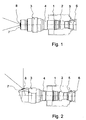
- the combustion chamber lens consists of a lens body 1 in which the electronic aperture control 2 is housed. in the Inside the lens body 1 there are two threaded rings. There is an eyepiece 5 in one threaded ring and in the another threaded ring screwed a reversal system 4.
- a lens head 3 is screwed onto the reversing system 4.
- the Reversing system 4 and the lens head 3 each contain one Lens system with an angle of view of 70 °, 94 ° or 110 ° is designed.
- the lens head 3 can with a straight view (Fig. 1) or with an oblique view of z. B. 70 ° to the lens axis (Fig. 2) be provided.
- the eyepiece 5 is for imaging on the image sensor Firebox camera designed.
- the eyepiece 5 is threaded provided, on which a filter housing 6 for receiving filters is screwed on.
- a protective glass 8 is on the lens head 3 in front of the front lens attached with the help of a clamping ring 7.
- the protective glass 8 holds Dust and dirt particles away from the front lens.
- the protective glass 8 can be unscrewed from the clamping ring 7 easy to remove and replace.
- the lens head 3 and the reversing system 4 are modular built up. They are geometrically the same for each assembly, whereby the overall length of the lens head 3 and the Reversing system 4 existing lenses for a picture angle of 70 ° is the same as the length of a lens for one 94 ° or 110 ° angle of view.
- the eyepiece 5 is for everyone Angle of view the same, so the overall length of the furnace probe between the eyepiece 5 and the front edge of the lens head 3 is always the same, regardless of the angle of view Lens is designed.
- the modular design of the lens head 3 and reversing system 4 has further the advantage that components that are on different Angles are designed, can be combined with each other, to get an intermediate angle. So the pairing results in one Reversing system 4 for a picture angle of 70 ° with a Lens head 3 for a picture angle of 94 ° a lens for a picture angle of 82 °. The combination of a 94 ° reversing system 4 with a 110 ° lens head 3 results in a Lens for a picture angle of 102 °.
Landscapes
- Physics & Mathematics (AREA)
- Engineering & Computer Science (AREA)
- General Physics & Mathematics (AREA)
- Optics & Photonics (AREA)
- Mechanical Engineering (AREA)
- General Engineering & Computer Science (AREA)
- Lenses (AREA)
- Structure And Mechanism Of Cameras (AREA)
Abstract
Description
- Fig. 1
- die Seitenansicht eines Feuerraumobjektives und
- Fig. 2
- die Seitenansicht eines Feuerraumobjektives gemäß einer anderen Ausführungsform.
Claims (4)
- Objektiv, insbesondere Feuerraumobjektiv zur Bildübertragung in Feuerräumen, bestehend aus einem Objektivkörper (1), in dem ein Okular (5) sowie ein Umkehrsystem (4) und ein Objektivkopf (3) montiert sind, wobei der Objektivkopf (3) und das Umkehrsystem (4) auswechselbar in den Objektivkörper (1) eingesetzt und jedem Objektiv die Objektivköpfe (3) mit unterschiedlichen Linsensystemen für bestimmte Bildwinkelaufnahmen und die Umkehrsysteme (4) mit Linsensystemen für bestimmte Bildwinkelaufnahmen zugeordnet sind dadurch gekennzeichnet, dass die dem Objektiv zugeordneten Objektivköpfe (3) und Umkehrsysteme (4) modular aufgebaut sind und für unterschiedliche Linsensysteme jeweils gleich große Abmessungen aufweisen, so dass die gesamte Baulänge des Objektivs von dem Okular (5) über das jeweils eingesetzte Umkehrsystem (4) bis zur Vorderkante des jeweils eingesetzten Objektivkopfes (3) konstant ist.
- Objektiv nach Anspruch 1, dadurch gekennzeichnet, dass der in den Objektivkörper (1) eingesetzte Objektivkopf (3) und das in den Objektivkörper (1) eingesetzte Umkehrsystem (4) auf dieselbe Bildwinkelaufnahme ausgelegt sind.
- Objektiv nach Anspruch 1, dadurch gekennzeichnet, dass der in den Objektivkörper (1) eingesetzte Objektivkopf (3) und das in den Objektivkörper (1) eingesetzte Umkehrsystem (4) auf unterschiedliche Bildwinkelaufnahmen ausgelegt sind.
- Objektiv nach einem der Ansprüche 1 bis 3, dadurch gekennzeichnet, dass vor der Frontlinse des Objektivkopfes (3) ein Schutzglas (8) auswechselbar befestigt ist.
Applications Claiming Priority (2)
| Application Number | Priority Date | Filing Date | Title |
|---|---|---|---|
| DE10211985 | 2002-03-18 | ||
| DE2002111985 DE10211985A1 (de) | 2002-03-18 | 2002-03-18 | Objektiv, insbesondere Feuerraumobjektiv |
Publications (1)
| Publication Number | Publication Date |
|---|---|
| EP1347325A1 true EP1347325A1 (de) | 2003-09-24 |
Family
ID=27771409
Family Applications (1)
| Application Number | Title | Priority Date | Filing Date |
|---|---|---|---|
| EP03005099A Withdrawn EP1347325A1 (de) | 2002-03-18 | 2003-03-07 | Objektiv zur Beobachtung eines Feuerraums |
Country Status (2)
| Country | Link |
|---|---|
| EP (1) | EP1347325A1 (de) |
| DE (1) | DE10211985A1 (de) |
Cited By (1)
| Publication number | Priority date | Publication date | Assignee | Title |
|---|---|---|---|---|
| DE102005041004A1 (de) * | 2005-08-29 | 2007-03-01 | Cmv Systems Gmbh & Co.Kg | Verfahren und Vorrichtung zur Überwachung der Bildung von Ansätzen in Feuerräumen |
Citations (3)
| Publication number | Priority date | Publication date | Assignee | Title |
|---|---|---|---|---|
| US4249793A (en) * | 1978-04-07 | 1981-02-10 | Nippon Kogaku K.K. | Erect type zoom telescopic optical system |
| US5321546A (en) * | 1991-09-26 | 1994-06-14 | Olympus Optical Co., Ltd. | Switching variable magnification finder |
| EP1081527A2 (de) * | 1999-09-01 | 2001-03-07 | Canon Kabushiki Kaisha | Optisches Beobachtungssystem und optisches Gerät unter Verwendung desselben |
Family Cites Families (1)
| Publication number | Priority date | Publication date | Assignee | Title |
|---|---|---|---|---|
| DE2919678C3 (de) * | 1979-05-16 | 1983-03-24 | Fa. Carl Zeiss, 7920 Heidenheim | Zusatzobjektive für binokulare Operationsmikroskope |
-
2002
- 2002-03-18 DE DE2002111985 patent/DE10211985A1/de not_active Withdrawn
-
2003
- 2003-03-07 EP EP03005099A patent/EP1347325A1/de not_active Withdrawn
Patent Citations (3)
| Publication number | Priority date | Publication date | Assignee | Title |
|---|---|---|---|---|
| US4249793A (en) * | 1978-04-07 | 1981-02-10 | Nippon Kogaku K.K. | Erect type zoom telescopic optical system |
| US5321546A (en) * | 1991-09-26 | 1994-06-14 | Olympus Optical Co., Ltd. | Switching variable magnification finder |
| EP1081527A2 (de) * | 1999-09-01 | 2001-03-07 | Canon Kabushiki Kaisha | Optisches Beobachtungssystem und optisches Gerät unter Verwendung desselben |
Non-Patent Citations (1)
| Title |
|---|
| BERGMANN, LUDWIG: "Lehrbuch der Experimentalphysik, Bd. 3 Optik", 1987, DE GRUYTER, BERLIN, D, XP002238165 * |
Cited By (2)
| Publication number | Priority date | Publication date | Assignee | Title |
|---|---|---|---|---|
| DE102005041004A1 (de) * | 2005-08-29 | 2007-03-01 | Cmv Systems Gmbh & Co.Kg | Verfahren und Vorrichtung zur Überwachung der Bildung von Ansätzen in Feuerräumen |
| EP1760401A3 (de) * | 2005-08-29 | 2009-03-04 | CMV Systems GmbH | Verfahren und Vorrichtung zur Überwachung der Bildung von Ansätzen in Feuerräumen |
Also Published As
| Publication number | Publication date |
|---|---|
| DE10211985A1 (de) | 2003-10-02 |
Similar Documents
| Publication | Publication Date | Title |
|---|---|---|
| DE602004008643T2 (de) | Nachtsicht-zielvisier mit zwei okularen | |
| DE69707866T2 (de) | Endoskopische sonde zur untersuchung einer koksofenbatterie | |
| DE19718189A1 (de) | Vorrichtung zur Lageveränderung eines optischen Abbildungssystems | |
| DE69306013T2 (de) | Aufbau einer Brennsaum-Überwachungskamera | |
| EP1721214A1 (de) | Vorrichtung zum verbinden eines kameraobjektivs mit einer laufbildkamera | |
| EP1291698B1 (de) | Vorrichtung zum Positionieren von Bauelementen innerhalb endoskopischer Systeme | |
| DE2715231C3 (de) | Umstellbarer Sucherzubehörteil für eine einäugige Spiegelreflexkamera | |
| DE2900282A1 (de) | Verfahren und vorrichtung zum fokussieren einer objektivlinsenanordnung eines endoskops | |
| DE10211985A1 (de) | Objektiv, insbesondere Feuerraumobjektiv | |
| DE3873340T2 (de) | Einrichtung zur ueberwachung von heissgehenden oefen. | |
| EP2161607B1 (de) | Dentalkamera | |
| DE1152603B (de) | Spiegelreflexkamera mit fest ein- bzw. angebauten Einrichtungen zur Betrachtung des Sucherbildes | |
| EP1058860B1 (de) | Kamera und insbesondere modulare dentalkamera | |
| DE10207665A1 (de) | Überwachungskamerasystem und Objektivsystem | |
| DE8711421U1 (de) | Schnellkupplung zwischen einem Endoskop und einer Kamera | |
| WO2016124319A2 (de) | Endoskop | |
| DE3436651A1 (de) | Fernsehkamera zur beobachtung von feuerraeumen | |
| DE4401941C2 (de) | An einem Versorgungskabel angebrachte Vorrichtung zur Untersuchung von zur direkten augenscheinlichen Betrachtung unzugänglichen Hohlräumen, z. B. Rohren und Brunnen | |
| DE202014100544U1 (de) | Schützenkontroll- und Zielaufnahmekamerasystem | |
| DE29718058U1 (de) | Endoskop | |
| DE19927730A1 (de) | Optisches Vorsatzsystem für eine Kamera | |
| DE3423320A1 (de) | Zieleinrichtung fuer eine handfeuerwaffe | |
| DE2659646C2 (de) | Fernsehkamera | |
| DE8428377U1 (de) | Zoomobjektivfassung | |
| DE20214856U1 (de) | Bohrlochsonde zur optischen Erfassung der inneren Wandung von Bohrlöchern und Schächten |
Legal Events
| Date | Code | Title | Description |
|---|---|---|---|
| PUAI | Public reference made under article 153(3) epc to a published international application that has entered the european phase |
Free format text: ORIGINAL CODE: 0009012 |
|
| AK | Designated contracting states |
Kind code of ref document: A1 Designated state(s): AT BE BG CH CY CZ DE DK EE ES FI FR GB GR HU IE IT LI LU MC NL PT SE SI SK TR |
|
| AX | Request for extension of the european patent |
Extension state: AL LT LV MK RO |
|
| 17P | Request for examination filed |
Effective date: 20031212 |
|
| 17Q | First examination report despatched |
Effective date: 20040115 |
|
| AKX | Designation fees paid |
Designated state(s): AT BE BG CH CY CZ DE DK EE ES FI FR GB GR HU IE IT LI LU MC NL PT SE SI SK TR |
|
| GRAP | Despatch of communication of intention to grant a patent |
Free format text: ORIGINAL CODE: EPIDOSNIGR1 |
|
| STAA | Information on the status of an ep patent application or granted ep patent |
Free format text: STATUS: THE APPLICATION IS DEEMED TO BE WITHDRAWN |
|
| 18D | Application deemed to be withdrawn |
Effective date: 20060711 |