EP1348848A2 - Turbocharger - Google Patents

Turbocharger Download PDF

Info

Publication number
EP1348848A2
EP1348848A2 EP03006640A EP03006640A EP1348848A2 EP 1348848 A2 EP1348848 A2 EP 1348848A2 EP 03006640 A EP03006640 A EP 03006640A EP 03006640 A EP03006640 A EP 03006640A EP 1348848 A2 EP1348848 A2 EP 1348848A2
Authority
EP
European Patent Office
Prior art keywords
turbocharger
air flow
lead
passage
motor
Prior art date
Legal status (The legal status is an assumption and is not a legal conclusion. Google has not performed a legal analysis and makes no representation as to the accuracy of the status listed.)
Granted
Application number
EP03006640A
Other languages
German (de)
French (fr)
Other versions
EP1348848B1 (en
EP1348848A3 (en
Inventor
Shoji c/o Toyota Jidosha K. K. Sasaki
Osamu c/o Toyota Jidosha K. K. Igarashi
Koichi c/o Toyota Jidosha K. K. Akita
Hiromasa c/o Toyota Jidosha K. K. Hashimoto
Kei c/o Toyota Jidosha K. K. Masuda
Chika c/o Toyota Jidosha K. K. Kanba
Current Assignee (The listed assignees may be inaccurate. Google has not performed a legal analysis and makes no representation or warranty as to the accuracy of the list.)
Toyota Motor Corp
Original Assignee
Toyota Motor Corp
Priority date (The priority date is an assumption and is not a legal conclusion. Google has not performed a legal analysis and makes no representation as to the accuracy of the date listed.)
Filing date
Publication date
Application filed by Toyota Motor Corp filed Critical Toyota Motor Corp
Publication of EP1348848A2 publication Critical patent/EP1348848A2/en
Publication of EP1348848A3 publication Critical patent/EP1348848A3/en
Application granted granted Critical
Publication of EP1348848B1 publication Critical patent/EP1348848B1/en
Anticipated expiration legal-status Critical
Expired - Lifetime legal-status Critical Current

Links

Images

Classifications

    • FMECHANICAL ENGINEERING; LIGHTING; HEATING; WEAPONS; BLASTING
    • F02COMBUSTION ENGINES; HOT-GAS OR COMBUSTION-PRODUCT ENGINE PLANTS
    • F02BINTERNAL-COMBUSTION PISTON ENGINES; COMBUSTION ENGINES IN GENERAL
    • F02B37/00Engines characterised by provision of pumps driven at least for part of the time by exhaust
    • F02B37/04Engines with exhaust drive and other drive of pumps, e.g. with exhaust-driven pump and mechanically-driven second pump
    • F02B37/10Engines with exhaust drive and other drive of pumps, e.g. with exhaust-driven pump and mechanically-driven second pump at least one pump being alternatively or simultaneously driven by exhaust and other drive, e.g. by pressurised fluid from a reservoir or an engine-driven pump
    • FMECHANICAL ENGINEERING; LIGHTING; HEATING; WEAPONS; BLASTING
    • F02COMBUSTION ENGINES; HOT-GAS OR COMBUSTION-PRODUCT ENGINE PLANTS
    • F02BINTERNAL-COMBUSTION PISTON ENGINES; COMBUSTION ENGINES IN GENERAL
    • F02B39/00Component parts, details, or accessories relating to, driven charging or scavenging pumps, not provided for in groups F02B33/00 - F02B37/00
    • F02B39/005Cooling of pump drives
    • FMECHANICAL ENGINEERING; LIGHTING; HEATING; WEAPONS; BLASTING
    • F02COMBUSTION ENGINES; HOT-GAS OR COMBUSTION-PRODUCT ENGINE PLANTS
    • F02BINTERNAL-COMBUSTION PISTON ENGINES; COMBUSTION ENGINES IN GENERAL
    • F02B39/00Component parts, details, or accessories relating to, driven charging or scavenging pumps, not provided for in groups F02B33/00 - F02B37/00
    • F02B39/02Drives of pumps; Varying pump drive gear ratio
    • F02B39/08Non-mechanical drives, e.g. fluid drives having variable gear ratio
    • F02B39/10Non-mechanical drives, e.g. fluid drives having variable gear ratio electric
    • YGENERAL TAGGING OF NEW TECHNOLOGICAL DEVELOPMENTS; GENERAL TAGGING OF CROSS-SECTIONAL TECHNOLOGIES SPANNING OVER SEVERAL SECTIONS OF THE IPC; TECHNICAL SUBJECTS COVERED BY FORMER USPC CROSS-REFERENCE ART COLLECTIONS [XRACs] AND DIGESTS
    • Y02TECHNOLOGIES OR APPLICATIONS FOR MITIGATION OR ADAPTATION AGAINST CLIMATE CHANGE
    • Y02TCLIMATE CHANGE MITIGATION TECHNOLOGIES RELATED TO TRANSPORTATION
    • Y02T10/00Road transport of goods or passengers
    • Y02T10/10Internal combustion engine [ICE] based vehicles
    • Y02T10/12Improving ICE efficiencies

Definitions

  • the turbocharger unit 11 can perform regenerative electric power generation by rotating the motor 11b via the turbine/compressor 11a using the exhaust energy, and recover the generated electric power.
  • the motor 11b includes a rotor (a permanent magnet) fixed to the rotating shaft of the turbine/compressor 11a, and a stator disposed around the rotor (i.e., a coil wound around an iron core), as main component portions.
  • the turbine/compressor 11a and the motor 11b are housed inside a housing 11c.
  • the air-cooling type intercooler 12 is disposed on the downstream side of the turbocharger unit 11 in the intake passage 5 so as to lower the temperature of the intake air whose temperature has risen with an increase in the pressure due to the supercharging by the turbocharger unit 11.
  • the intercooler 12 lowers the temperature of the intake air, thereby improving the efficiency in filling the intake passage 5 with air.
  • a lead-in passage 25 and a lead-out passage 26 are provided in association with the turbocharger unit 11.
  • One end of the lead-in passage 25 is connected to the housing 11c of the turbocharger unit 11, and the other end thereof is connected to a portion between the intercooler 12 and the throttle valve 13. Additional intake air is supplied into the intake passage 5 past the turbocharger unit 11 by the compressor of the turbocharger unit 11. Therefore, a portion of the intake air is led into the inside of the housing 11c via the lead-in passage 25. In other words, an air flow that leads air outside the housing 11c (intake air) into the inside of the housing 11c is generated inside the lead-in passage 25.
  • the compressor of the turbocharger unit 11 functions as the air flow generation means.
  • the adjusting amount valve 27 is used to increase the amount of the air led into the inside of the housing 11c.
  • the relation between the pressure ratio of the compressor and the flow amount becomes appropriate, and the surge can be avoided.
  • Whether or not the engine 1 is in the surge region can be determined based on a pressure in an intake pipe detected by a pressure sensor 19, an atmospheric pressure detected by an atmospheric pressure sensor, the amount of intake air detected by an air flow meter, and the like.
  • the other end of the lead-in passage 25 is opened to air.
  • the component that generates, inside the lead-in passage 25, the air flow directed toward the inside of the housing 11c is the lead-out passage 26 which connects the housing 11c and the portion of the intake passage 5 on the upstream side of the turbocharger unit 11.
  • the lead-out passage 26 that connects the housing 11c and the portion of the intake passage 5 on the upstream side of the turbocharger unit 11 functions as the air flow generation means.
  • the cooling of the motor 11b is performed without using intake air, there is little necessity of installing a component such as the adjusting amount valve 27 in the first embodiment. Therefore, such a component is not installed.
  • the motor 11b can be cooled using the simple structure.

Landscapes

  • Engineering & Computer Science (AREA)
  • Chemical & Material Sciences (AREA)
  • Combustion & Propulsion (AREA)
  • Mechanical Engineering (AREA)
  • General Engineering & Computer Science (AREA)
  • Supercharger (AREA)
  • Output Control And Ontrol Of Special Type Engine (AREA)

Abstract

A turbocharger (11) according to the invention is characterized by including a motor (11b) that can rotationally drive a turbine/compressor (11a), a turbocharger housing (11c) in which the motor (11b) is mounted, a lead-in passage (25) one end of which is connected to the housing (11c), and air flow generation means (11a) that generates, in the lead-in passage (25), an air flow directed toward the inside of the housing (11c). This turbocharger (11) makes it possible to cool the motor (11b) in a simple manner, and to prevent a reduction in the efficiency of the motor (11b).

Description

BACKGROUND OF THE INVENTION 1. Field of the Invention
The invention relates to a turbocharger with a motor in which a compressor and/or a turbine of the turbocharger can be driven by the motor.
2. Description of Related Art
An attempt has been conventionally made in which intake air of an engine (an internal combustion engine) is supercharged using a turbocharger so as to obtain high output (or low fuel consumption). One of the points to be improved in the turbocharger is that a supercharged pressure cannot be obtained quickly while an engine is in a low revolution region, and engine output characteristics in the low revolution region are not good. This is a phenomenon which occurs in the low revolution region where exhaust energy is low, due to the principle of the turbocharger that the exhaust energy is used to supercharge intake air. In order to improve this point, a twin turbo system and the like are generally employed. Also, an attempt has been made in which a motor is mounted in a turbine and/or compressor so as to forcibly drive the turbine, thereby obtaining a desired supercharged pressure. One example of such a turbocharger with a motor is disclosed in Patent Document 1.
[Patent Document 1] Japanese Patent Laid-Open Publication No. 2-99722
However, in such a turbocharger with a motor, the motor is exposed to high temperatures, which causes problems, such as degauss (or demagnetization) of a permanent magnet inside the motor, or a reduction in the efficiency of the motor due to a rise in temperature, depending on the types of the motor. Also, in a case where an induction motor is employed as the motor, there may be a problem that a laminate material with low heat resistance for solidifying a laminated steel plate used as a rotor melts. Therefore, in the turbocharger with a motor disclosed in the aforementioned Patent Document 1 and the like, a vane for introducing outside air into the inside of the motor is provided, thereby performing air cooling. However, according to this method, the vane is incorporated in the motor, which causes a problem that the internal structure of the motor becomes complicated.
SUMMARY OF THE INVENTION
Accordingly, it is an object of the invention to provide a turbocharger which can cool a motor in a simple manner, and which can prevent a reduction in the efficiency of the motor.
According to an exemplary embodiment of the invention, a turbocharger which performs supercharging for an internal combustion engine includes a compressor, a turbine, a motor which can rotationally drive the compressor and/or the turbine, and a turbocharger housing in which the motor is mounted. The turbocharger which performs supercharging for the internal combustion engine further includes a lead-in passage whose one end is connected to the housing, and air flow generation means for generating, in the lead-in passage, an air flow directed toward the inside of the housing.
According to the turbocharger as mentioned above, the lead-in passage is provided, and the air flow generation means generates the air flow directed toward the turbocharger housing in which the motor is mounted. As a result, the motor is cooled by the generated air flow, and a reduction in efficiency due to a rise in temperature is prevented. Also, cooling of the motor can be realized using the simple structure, that is, the lead-in passage and the air flow generation means.
Also, according to a further aspect of the invention, in the turbocharger, it is preferable that the other end of the lead-in passage should be connected to a portion on a downstream side of an intercooler in an intake passage.
According to the turbocharger as mentioned above, the intake air on the downstream side of the intercooler is led into the housing, whereby the motor can be cooled with good cooling efficiency, using the intake air whose temperature has been lowered.
Also, according to a further aspect of the invention, in the turbocharger, it is preferable that a lead-out passage should be connected to the housing in order to discharge the air flow from the inside of the housing.
According to the turbocharger as mentioned above, the air in the housing which has cooled the motor can be led into the lead-out passage quickly, and the motor can be cooled with good efficiency.
Also, according to a further aspect of the invention, in the turbocharger, it is preferable that the air flow generation means should be a compressor.
By utilizing the compressor of the turbocharger as the air flow generation means in this manner, an actuator for generating an air flow or the like does not need to be newly added, and the motor can be cooled with good energy efficiency using the simple structure.
Also, according to a further aspect of the invention, it is preferable that the turbocharger should further include cooling control means for controlling the air flow generation means when the motor is cooled by the air flow generated by the air flow generation means, and the cooling control means should limit generation of the air flow by the air flow generation means when a required output of the internal combustion engine is equal to or higher than a predetermined value.
Also, according to a further aspect of the invention, it is preferable that the turbocharger should further include output control means for controlling an output of the internal combustion engine, and the output control means should compensate for an output fluctuation of the internal combustion engine, which is caused by leading the air flow to the motor when the air flow is generated by the air flow generation means.
Also, according to a further aspect of the invention, in the turbocharger, the output control means should perform increase correction so that an amount of fuel injection increases with an increase in an amount of the air flow led to the motor when the air flow is generated by the air flow generation means.
Also, according to a further aspect of the invention, it is preferable that the turbocharger should further include a lead-out passage one end of which is connected to the housing, and the other end of which is connected to a portion upstream of the compressor in the intake passage of the internal combustion engine, and the other end of the lead-in passage should be opened to air.
In the turbocharger thus configured, the lead-out passage functions as the air flow generation means. Since intake air is not used for cooling the motor, the motor can be cooled using the simple structure.
Also, according to a further aspect of the invention, it is preferable that the turbocharger should further include a lead-out passage one end of which is connected to the housing, and the other end of which is opened to air, and a fan that generates the air flow should be provided inside the lead-in passage.
Also, according to a further aspect of the invention, it is preferable that the turbocharger should further include a lead-out passage one end of which is connected to the housing, and the other end of which is opened to air, and a fan that generates the air flow should be provided inside the lead-out passage.
In the turbocharger thus configured, the fan that generates the air flow is provided inside the lead-in passage or inside the lead-out passage. Therefore, the air flow can be generated quickly, and accordingly, the cooling of the motor can be performed smoothly. In addition, disposing the fan away from the motor is advantageous in terms of heat resistance.
BRIEF DESCRIPTION OF THE DRAWINGS
The above and other objects, features, advantages, technical and industrial significances of this invention will be better understood by reading the following detailed description of preferred embodiments of the invention, when considered in connection with the accompanying drawings, in which:
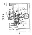
  • FIG. 1 is a view showing a configuration of an engine having a turbocharger according to a first embodiment of the invention;
  • FIG. 2 is a flowchart of a control which limits cooling by an air flow when a required output of an engine is high;
  • FIG. 3 is a map showing a relation between a coefficient α in the flowchart in FIG. 2 and the required output;
  • FIG. 4 is a view showing a configuration of an engine having a turbocharger according to a second embodiment of the invention;
  • FIG. 5 is a view showing a configuration of an engine having a turbocharger according to a third embodiment of the invention;
  • FIG. 6 is a view showing a configuration of an engine having a turbocharger according to a forth embodiment of the invention.
  • DESCRIPTION OF THE EXEMPLARY EMBODIMENTS
    In the following description and the accompanying drawings, the present invention will be described in more detail in terms of exemplary embodiments.
    [First Embodiment]
    First, a turbocharger according to a first embodiment among turbochargers according to exemplary embodiments will be described. An engine 1 having this turbocharger according to the first embodiment is shown in FIG. 1. Although the engine 1 which will be described in the embodiment is an in-cylinder injection type gasoline engine, the invention can be applied to a type of gasoline engine in which fuel is injected to an intake passage, or a diesel engine.
    The engine 1 which will be described in the embodiment is a multi-cylinder engine. However, only one cylinder among the multiple cylinders is shown in FIG. 1 as a cross sectional view. The engine 1 is a type of engine in which an injector 2 injects fuel to an upper surface of a piston 4 in a cylinder 3. In this engine 1, stratified charge combustion can be performed. Thus, it is a so called lean burn engine. By supercharging more intake air using a turbocharger described later so as to perform lean burn, it is possible to realize low fuel consumption as well as high output in the engine 1.
    In the engine 1, air inhaled into the cylinder 3 through an intake passage 5 is compressed by the piston 4, fuel is injected to a concavity formed in the upper surface of the piston 4 so that a dense air-fuel mixture is concentrated in the vicinity of a plug 7, and this air-fuel mixture is ignited by the plug 7 so as to be burnt. An intake valve 8 opens and closes a portion between the inner portion of the cylinder 3 and the intake passage 5. Exhaust gas is discharged to an exhaust passage 6. A discharge valve 9 opens and closes a portion between the inner portion of the cylinder 3 and the exhaust passage 6. In the intake passage 5, an air cleaner 10, a turbocharger unit 11, an intercooler 12, a throttle valve 13 and the like are disposed in this order from the upstream side to the downstream side.
    The air cleaner 10 is a filter which removes dirt, dust, and the like. The turbocharger unit 11 is disposed between the intake passage 5 and the exhaust passage 6 so as to perform supercharging. In the turbocharger unit 11 according to the embodiment, an impeller on the turbine side and an impeller on the compressor side are connected by a rotating shaft (hereinafter, this portion is simply referred to as a turbine/compressor 11a). In addition, the turbocharger according to the embodiment is a turbocharger with a motor in which a motor 11b is incorporated so that the rotating shaft of the turbine/compressor 11a becomes an output shaft. The motor 11b is an alternate current motor, and functions as an electric generator as well as a motor. The turbocharger unit 11 can function as an ordinary supercharger which performs supercharging using only exhaust energy. In addition, the turbocharger unit 11 can perform further supercharging by forcibly driving the turbine/compressor 11a using the motor 11b.
    Also, the turbocharger unit 11 can perform regenerative electric power generation by rotating the motor 11b via the turbine/compressor 11a using the exhaust energy, and recover the generated electric power. The motor 11b includes a rotor (a permanent magnet) fixed to the rotating shaft of the turbine/compressor 11a, and a stator disposed around the rotor (i.e., a coil wound around an iron core), as main component portions. The turbine/compressor 11a and the motor 11b are housed inside a housing 11c. The air-cooling type intercooler 12 is disposed on the downstream side of the turbocharger unit 11 in the intake passage 5 so as to lower the temperature of the intake air whose temperature has risen with an increase in the pressure due to the supercharging by the turbocharger unit 11. The intercooler 12 lowers the temperature of the intake air, thereby improving the efficiency in filling the intake passage 5 with air.
    The throttle valve 13 which adjusts the amount of intake air is disposed on the downstream side of the intercooler 12. The throttle valve 13 according to the embodiment is a so called electronically controlled throttle valve. An accelerator positioning sensor 15 detects the operation amount of an accelerator pedal 14. Based on the result of the detection and other information, an electronic control unit (hereinafter it is referred to as ECU) 16 determines the opening of the throttle valve 13. The throttle valve 13 is opened and closed by a throttle motor 17 which is provided in association with the throttle valve 13. Also, a throttle positioning sensor 18 which detects the opening of the throttle valve 13 is provided in association with the throttle valve 13.
    Also, a lead-in passage 25 and a lead-out passage 26 are provided in association with the turbocharger unit 11. One end of the lead-in passage 25 is connected to the housing 11c of the turbocharger unit 11, and the other end thereof is connected to a portion between the intercooler 12 and the throttle valve 13. Additional intake air is supplied into the intake passage 5 past the turbocharger unit 11 by the compressor of the turbocharger unit 11. Therefore, a portion of the intake air is led into the inside of the housing 11c via the lead-in passage 25. In other words, an air flow that leads air outside the housing 11c (intake air) into the inside of the housing 11c is generated inside the lead-in passage 25. In the embodiment, the compressor of the turbocharger unit 11 functions as the air flow generation means.
    The air is led into the inside of the housing 11c from the outside in this manner, whereby the motor 11b can be cooled, and a reduction in the efficiency due to reasons such as the degauss of the permanent magnet inside the motor 11b can be prevented. Particularly in the embodiment, the intake air is led into the inside of the housing 11c from the intake passage 5 using the lead-in passage 25. Thus, the basic structure is a structure in which the lead-in passage 25 is simply added to the engine having an ordinary turbocharger. Therefore, the turbocharger according to the embodiment can be realized using the extremely simple structure. In addition, since the intake air which has been cooled by the intercooler 12 is led into the inside of the housing 11c, the cooling efficiency is good.
    It is preferable, in terms of the cooling efficiency, that the intake air for cooling which has been led into the inside of the housing 11c should be discharged to the outside of the housing 11c quickly after cooling. In this case, the lead-out passage 26 which connects the housing 11c and a portion of the intake passage 5 on the upstream side of the turbocharger unit 11 is provided. By providing this lead-out passage 26, it is possible to quickly discharge the air which has been used for cooling from the inside of the housing 11c, to easily lead fresh air for cooling into the inside of the housing 11c, and to further improve the cooling efficiency.
    Particularly, the pressure inside the portion of the intake passage 5 on the upstream side of the turbocharger unit 11 frequently becomes vacuum (the frequency with which the pressure becomes vacuum becomes high due to the supercharging by the turbocharger unit 11). Therefore, connecting one end of the lead-out passage 26 to this portion is preferable, because it allows the air to be discharged from the inside of the housing 11c more efficiently. For this reason, it can be considered that the lead-out passage 26 according to the embodiment which connects the housing 11c and the portion of the intake passage 5 on the upstream side of the turbocharger unit 11 functions also as the air flow generation means.
    Further, according to the embodiment, an adjusting amount valve 27 which adjusts the amount of air led into the housing 11c is provided in the lead-in passage 25. The adjusting amount valve 27 is connected to the ECU 16, and the amount of air led into the housing 11c can be controlled by the ECU 16. For example, it is possible to detect the temperature inside the turbocharger unit 11 using a sensor or the like, to determine whether or not the air for cooling needs to be supplied to the inside of the housing 11c, and to control the amount of the air led into the inside of the housing 11c when the air needs to be supplied thereto. Thus, it is possible to efficiently prevent a decrease in the amount of the intake air supplied to the cylinder 3 due to leading the intake air into the housing 11c.
    Further, when supercharging is performed by driving the motor 11b while the engine 1 is in the low revolution region, in a case where the engine 1 reaches a region in which a surge of the compressor occurs, or other cases, the adjusting amount valve 27 is used to increase the amount of the air led into the inside of the housing 11c. As a result, the relation between the pressure ratio of the compressor and the flow amount becomes appropriate, and the surge can be avoided. Whether or not the engine 1 is in the surge region can be determined based on a pressure in an intake pipe detected by a pressure sensor 19, an atmospheric pressure detected by an atmospheric pressure sensor, the amount of intake air detected by an air flow meter, and the like.
    Also, according to the first embodiment, since air is led into the inside of the housing 11c from the outside without using the vane or the like, the cooling can be performed efficiently. When the vane is used, the output of the motor is used to rotate the vane, which is not preferable in terms of efficiency. In addition, when the vane is used, the inertial weight of the rotating portion increases due to the vane, which deteriorates the response of the turbocharger. According to the embodiment, however, such a phenomenon does not occur. Further, since the component portion of the vane or the like in the aforementioned [Patent Publication 1] is exposed to high temperatures, a material with excellent heat resistance or the like needs to be used. According to the embodiment, however, such a material does not need to be used.
    In the first embodiment, a portion of intake air is led into the turbocharger unit 11 from the downstream side of the intercooler 12 in order to perform cooling. Therefore, there is a possibility that the amount of intake air decreases and accordingly the output of the engine 1 decreases when cooling the turbocharger unit 11. Cases where this phenomenon is avoided will be described below.
    First, a case where the cooling of the turbocharger unit 11 is restricted according to the required output of the engine 1 will be described. In this case, when the required output of the engine 1 is equal to or higher than a predetermined value, the cooling of the turbocharger unit 11 is restricted (that is, the cooling is made difficult, the cooling is inhibited, or the effect of the cooling is reduced). When the required output of the engine 1 is equal to or higher than the predetermined value, that is, when higher output is required, there is a possibility that the required output cannot be obtained if the amount of intake air decreases due to the cooling of the turbocharger unit 11. Therefore, by restricting the cooling, priority is given to realizing the required output.
    In this case, the aforementioned accelerator positioning sensor 15 detects the depression amount of the accelerator pedal 14, and this depression amount is regarded as the required output of the engine 1. The output of the engine 1 depends mainly on the amount of intake air, the amount of fuel injection, ignition timing, and the like. Therefore, the value of the required output which is calculated in the ECU 16 based on these parameters may be used. The amount of intake air can be detected using the opening of the throttle valve 13 and the pressure sensor, and the amount of fuel injection can be determined using the opening time of the injector 2. In other words, the required output is determined by the ECU 16.
    When the required output thus detected is equal to or higher than the predetermined value, a decrease in the output due to the cooling using the air flow can be avoided by closing the adjusting amount valve 27 so that the cooling of the turbocharger unit 11 using the lead-in passage 25 is not performed. Alternatively, the opening of the adjusting amount valve 27 may be controlled to be variable so that the amount of the air flow led into the turbocharger unit 11 from the downstream side of the intercooler 12 decreases. Further, the aforementioned predetermined output may be a fixed value independently of the required output (the depression amount of the accelerator pedal 14), or may be controlled to be variable depending on the required output. In the embodiment, the control of the flowchart shown in FIG. 2 is performed.
    First, an adjusting amount valve opening and closing reference temperature A is set to a value "a" (step S200). The adjusting amount valve opening and closing reference temperature A is a reference for determining whether or not the cooling is to be performed by opening the adjusting amount valve 27 and leading the air flow into the inside of the turbocharger unit 11 via the lead-in passage 25. If the temperature of the turbocharger unit 11 is equal to or lower than a practical durable temperature, the cooling does not need to be performed. Therefore, the reference temperature A is set so that the cooling is performed only when the temperature of the motor 11b exceeds the reference temperature A. Thus, the energy consumption can be reduced by preventing the compressor 11c that generates the air flow from being driven, and a decrease in the output due to the cooling can be prevented by reducing the frequency with which the cooling is performed. Following step S200, it is determined whether the required output of the engine 1 is equal to or higher than the predetermined value (step S210).
    When the required output of the engine 1 is equal to or higher than the predetermined value, the reference temperature A is increased so that the cooling is restricted as mentioned above. In fact, the reference temperature A is newly set to the product of the aforementioned value "a" and a coefficient α (>1) (step S220). When the required output of the engine 1 is less than the predetermined value, this step S220 is not performed, and the reference temperature A remains at the initial value (= "a"). In this case, the value α may be a fixed value (for example, 1.2), or may be variable depending on the required output (the depression amount of the accelerator pedal 14) as shown in FIG. 3.
    Next, the temperature of the motor 11b is detected. When the temperature is equal to or lower than the reference temperature A, the adjusting amount valve 27 is not closed, and the cooling is not performed (step S240). On the other hand, when the temperature of the motor 11b exceeds the reference temperature A, the adjusting amount valve 27 is opened, and the cooling is performed (step S250). The temperature of the motor 11b is detected using a temperature sensor incorporated in the stator coil or the like inside the motor 11b, or is estimated using the integrated value obtained by integrating time after electric current starts to flow, or by other methods. Thus, since the reference temperature A is increased when the required output is equal to or higher than the predetermined value, the cooling using the air flow can be restricted. As a result, a decrease in the output due to a reduction in the amount of intake air can be avoided (or suppressed).
    The compressor 11a that generates such an air flow, the adjusting amount valve 27, the ECU 16 that controls the compressor 11a and the adjusting amount valve 27, and the like function as the cooling control means. The case where a decrease in the output is avoided by restricting the cooling according to the required output of the engine 1 has been described. However, a decrease in the output may be avoided by compensating for the output of the engine 1 at the time of cooling. For example, when the cooling of the motor 11b is performed using the air flow, a decrease in the output due to a reduction in the amount of air led into the cylinder 3 can be compensated for by increasing the amount of fuel injection.
    In this case, the output is compensated for by setting a coefficient which varies depending on whether or not the cooling of the motor 11b is being performed (for example, when the cooling is not being performed: 1.0, when the cooling is being performed: 1.1), and obtaining the product of this coefficient and the amount of fuel injection. Alternatively, the output may be compensated for by controlling the injection timing. Alternatively, the opening of the throttle valve 13 may be increased so as to increase the amount of intake air, allowing for a reduction in the air led into the cylinder 3 due to the cooling. In this case, the injector 2, the throttle valve 13, the ECU 16, and the like function as the output control means.
    [Second Embodiment]
    Next, a turbocharger according to a second embodiment of the invention will be described. FIG. 4 shows the turbocharger according to the second embodiment in the same manner as FIG. 1 which shows the turbocharger according to the first embodiment. The configuration of each portion in the second embodiment is almost the same as that in the first embodiment. Therefore, the components which are the same as, or equivalent to those in the first embodiment are denoted by the same reference numerals, and the detailed description thereof will be omitted. Particularly, the components which are different from those in the first embodiment will be described in detail below.
    In the second embodiment, the other end of the lead-in passage 25 is opened to air. In addition, the component that generates, inside the lead-in passage 25, the air flow directed toward the inside of the housing 11c is the lead-out passage 26 which connects the housing 11c and the portion of the intake passage 5 on the upstream side of the turbocharger unit 11. In other words, in the second embodiment, the lead-out passage 26 that connects the housing 11c and the portion of the intake passage 5 on the upstream side of the turbocharger unit 11 functions as the air flow generation means. In the second embodiment, since the cooling of the motor 11b is performed without using intake air, there is little necessity of installing a component such as the adjusting amount valve 27 in the first embodiment. Therefore, such a component is not installed. In the second embodiment as well, the motor 11b can be cooled using the simple structure.
    [Third Embodiment]
    Next, a turbocharger according to a third embodiment of the invention will be described. FIG. 5 shows the turbocharger according to the third embodiment in the same manner as FIG. 1 which shows the turbocharger according to the first embodiment. The configuration of each portion in the third embodiment is also almost the same as that in the first embodiment. Therefore, the components which are the same as, or equivalent to those in the first embodiment are denoted by the same reference numerals, and the detailed description thereof will be omitted. Particularly, the components which are different from those in the first embodiment will be described in detail below.
    In the third embodiment, the ends of both the lead-in passage 25 and the lead-out passage 26 are opened to air. In addition, a fan 28 that generates, inside the lead-in passage 25, the air flow directed toward the inside of the housing 11c is provided inside the lead-in passage 25. The fan 28 is connected to the ECU 16, and the ECU 16 controls the fan 28. The fan 28 sends wind toward the housing 11c side. In the third embodiment, the fan 28 functions as the air flow generation means.
    Also, in the third embodiment, since the ECU 18 controls the fan 28, the air flow can be generated inside the lead-in passage 25 at any given time. It is preferable that the fan 28 should be driven only when necessary, because it consumes electric energy. Therefore, in the third embodiment, the temperature inside the housing 11c is detected by the temperature sensor, and based on the result of the detection, the driving of the fan 28 is controlled. In the third embodiment as well, the cooling of the motor 11b can be performed using the simple structure. Also, since the fan 28 is disposed away from the turbocharger unit 11, the fan 28 does not need to have as high heat resistance as the turbocharger unit 11.
    [Fourth Embodiment]
    Next, a turbocharger according to a fourth embodiment will be described. FIG. 6 shows the turbocharger according to the fourth embodiment in the same manner as FIG. 1 which shows the turbocharger according to the first embodiment. The configuration of each portion in the fourth embodiment is also almost the same as that in the first embodiment. Therefore, the components which are the same as, or equivalent to those in the first embodiment are denoted by the same reference numerals, and the detailed description thereof will be omitted. Particularly, the components which are different from those in the first embodiment will be described in detail below.
    In the fourth embodiment as well, the ends of both the lead-in passage 25 and the lead-out passage 26 are opened to air. In addition, the fan 28 that generates, inside the lead-in passage 25, the air flow directed toward the inside of the housing 11c is provided inside the lead-out passage 26. The fan 28 is connected to the ECU 16, and the ECU 16 controls the fan 28. The fan 28 generates, inside the lead-in passage 25, the air flow directed toward the inside of the housing 11c by sucking the air inside the housing 11c. In the fourth embodiment, the fan 28 (and the lead-out passage 26) function as the air flow generation means.
    In the fourth embodiment as well, the air flow can be generated inside the lead-in passage 25 at any given time. It is preferable that the fan 28 should be driven only when necessary, because it consumes electric energy. Therefore, in the fourth embodiment as well, the temperature inside the housing 11c is detected by the temperature sensor, and based on the result of the detection, the driving of the fan 28 is controlled. In the fourth embodiment as well, the cooling of the motor 11b can be performed using the simple structure. Also, since the fan 28 is disposed away from the turbocharger unit 11, the fan 28 does not need to have as high heat resistance as the turbocharger unit 11.
    Note that the invention is not limited to the aforementioned embodiments. For example, in the aforementioned embodiments, the output shaft of the motor 11b matches the rotating shaft of the turbine/compressor 11a. However, the invention can be applied to a turbocharger with a motor in which the output shaft of the motor 11b does not match the rotating shaft of the turbine/compressor 11a (for example, in a case where a speed reduction mechanism such as a gear is interposed).
    Also, in FIG. 1, the opening/closing valve (the adjusting amount valve 27) is provided only in the lead-in passage 25. However, the opening/closing valve may be provided also in the lead-out passage 26. In this case, when the air flow is led into the inside of the turbocharger unit 11, a change in the pressure inside the turbocharger unit 11 can be suppressed by simultaneously opening and closing the two opening/closing valves.
    In the turbocharger according to the invention, the lead-in passage is provided, and the air flow generation means generates the air flow directed toward the turbocharger housing in which the motor is mounted. As a result, the motor is cooled by the generated air flow, and a reduction in efficiency due to a rise in temperature is prevented. Also, the cooling of the motor can be realized using the simple structure, that is, the lead-in passage and the air flow generation means.
    In this case, by leading the intake air on the downstream side of the intercooler into the inside of the housing, the motor can be cooled efficiently using the intake air whose temperature has been lowered. Also, by utilizing the compressor of the turbocharger as the air flow generation means, an actuator that generates an air flow or the like does not need to be newly added, and the motor can be cooled with good energy efficiency using the simple structure.
    The turbocharger according to the invention (11) is characterized by including the motor (11b) which can rotationally drive the turbine/compressor (11a), the turbocharger housing (11c) in which the motor (11b) is mounted, the lead-in passage (25) one end of which is connected to the housing (11c), and the air flow generation means (11a) which generates, in the lead-in passage (25), the air flow directed toward the inside of the housing (lie). This turbocharger (11) makes it possible to cool the motor (11b) in a simple manner, and to prevent a reduction in the efficiency of the motor (11b).
    While the invention has been described with reference to exemplary embodiments thereof, is to be understood that the invention is not limited to the exemplary embodiments or constructions. To the contrary, the invention is intended to cover various modifications and equivalent arrangements. In addition, while the various elements of the exemplary embodiments are shown in various combinations and configurations, which are exemplary, other combinations and configurations, including more, less or only a single element, are also within the spirit and scope of the invention.
    A turbocharger (11) according to the invention is characterised by including a motor (11b) that can rotationally drive a turbine/compressor (11a), a turbocharger housing (11c) in which the motor (11b) is mounted, a lead-in passage (25) one end of which is connected to the housing (11c), and air flow generation means (11a) that generates, in the lead-in passage (25), an air flow directed toward the inside of the housing (11c). This turbocharger (11) makes it possible to cool the motor (11b) in a simple manner, and to prevent a reduction in the efficiency of the motor (11b).

    Claims (10)

    1. A turbocharger which includes a compressor (11a), a turbine (11a), a motor (11b) that can rotationally drive the compressor (11a) and/or the turbine (11a), and a turbocharger housing (11c) in which the motor (11b) is mounted, and which performs supercharging for an internal combustion engine (1), characterized by comprising:
      a lead-in passage (25) one end of which is connected to the housing (11c); and
      air flow generation means (11a, 26, 28) which generates, in the lead-in passage (25), an air flow directed toward an inside of the housing (11c).
    2. The turbocharger (11) according to claim 1, characterized in that
         the other end of the lead-in passage (25) is connected to a portion on downstream side of an intercooler (12) in an intake passage (5) of the internal combustion engine (1).
    3. The turbocharger (11) according to claim 1 or 2, characterized by further comprising:
      a lead-out passage (26) which is connected to the housing (11c) in order to discharge the air flow from the inside of the housing (11c).
    4. The turbocharger (11) according to any one of claims 1 to 3,
      characterized in that
         the air flow generation means is the compressor (11a).
    5. The turbocharger (11) according to any one of claims 2 to 4,
      characterized by further comprising:
      cooling control means (11a, 16, 27) for controlling the air flow generation means (11a) when the motor (11b) is cooled by the air flow generated by the air flow generation means (11a), and characterized in that
      the cooling control means (11a, 16, 27) limits generation of the air flow by the air flow generation means (11a) when a required output of the internal combustion engine is equal to or higher than a predetermined value.
    6. The turbocharger (11) according to any one of claims 2 to 4,
      characterized by further comprising:
      output control means (2, 13, 16) for controlling an output of the internal combustion engine (1), and characterized in that
      the output control means (2, 13, 16) compensates for an output fluctuation of the internal combustion engine (1), which is caused by leading the air flow to the motor (11b) when the air flow is generated by the air flow generation means (11a).
    7. The turbocharger (11) according to claim 6, characterized in that
         the output control means (2, 13, 16) performs increase correction so that an amount of fuel injection in the internal combustion engine (1) increases with an increase in an amount of the air flow led to the motor (11b) when the air flow is generated by the air flow generation means (11a).
    8. The turbocharger (11) according to claim 1, characterized by further comprising:
      a lead-out passage (26) one end of which is connected to the housing (11c), and the other end of which is connected to a portion upstream of the compressor (11a) in the intake passage of the internal combustion engine (1), and characterized in that
      the other end of the lead-in passage (25) is opened to air.
    9. The turbocharger (11) according to claim 1, characterized by further comprising:
      a lead-out passage (26) one end of which is connected to the housing (11c), and the other end of which is opened to air, and characterized in that
      a fan (28) that generates the air flow is provided inside the lead-in passage (25).
    10. The turbocharger (11) according to claim 1, characterized by further comprising:
      a lead-out passage (26) one end of which is connected to the housing (11c), and the other end of which is opened to air, and a fan (28) that generates the air flow is provided inside the lead-out passage (26).
    EP03006640A 2002-03-26 2003-03-25 Turbocharger Expired - Lifetime EP1348848B1 (en)

    Applications Claiming Priority (4)

    Application Number Priority Date Filing Date Title
    JP2002086334 2002-03-26
    JP2002086334 2002-03-26
    JP2002322764 2002-11-06
    JP2002322764A JP3843932B2 (en) 2002-03-26 2002-11-06 Turbocharger

    Publications (3)

    Publication Number Publication Date
    EP1348848A2 true EP1348848A2 (en) 2003-10-01
    EP1348848A3 EP1348848A3 (en) 2006-03-29
    EP1348848B1 EP1348848B1 (en) 2007-09-05

    Family

    ID=27807016

    Family Applications (1)

    Application Number Title Priority Date Filing Date
    EP03006640A Expired - Lifetime EP1348848B1 (en) 2002-03-26 2003-03-25 Turbocharger

    Country Status (3)

    Country Link
    EP (1) EP1348848B1 (en)
    JP (1) JP3843932B2 (en)
    DE (1) DE60316064T2 (en)

    Cited By (18)

    * Cited by examiner, † Cited by third party
    Publication number Priority date Publication date Assignee Title
    EP1749991A3 (en) * 2005-08-05 2007-11-14 IHI Corporation Supercharger with electric motor
    WO2008029211A1 (en) * 2006-09-06 2008-03-13 Toyota Jidosha Kabushiki Kaisha Electric supercharger
    US7352077B2 (en) 2005-08-08 2008-04-01 Ishikawajima-Harima Heavy Industries Co., Ltd. Motor-driven supercharger
    US7367190B2 (en) 2005-08-11 2008-05-06 Ihi Corp. Supercharger with electric motor
    US7559751B2 (en) 2005-08-22 2009-07-14 Ihi Corporation Supercharger with electric motor
    US7673452B2 (en) * 2006-01-24 2010-03-09 Ishikawajima-Harima Heavy Industries Co., Ltd. Motor-driven supercharger
    US7837448B2 (en) 2006-01-26 2010-11-23 Ishikawajima-Harima Heavy Industries Co., Ltd. Supercharger
    US8001781B2 (en) 2006-06-02 2011-08-23 Ihi Corporation Motor-driven supercharger
    US8096126B2 (en) 2006-06-02 2012-01-17 Ihi Corporation Motor-driven supercharger
    US8152489B2 (en) 2006-08-18 2012-04-10 Ihi Corporation Motor-driven supercharger
    US8157543B2 (en) 2006-03-23 2012-04-17 Ihi Corporation High-speed rotating shaft of supercharger
    US8157544B2 (en) 2006-08-18 2012-04-17 Ihi Corporation Motor driven supercharger with motor/generator cooling efficacy
    EP2733326A4 (en) * 2011-07-15 2015-11-18 Mitsubishi Heavy Ind Ltd ELECTRICAL POWER SUPPLY DEVICE AND MULTI-STAGE SUPER-POWER SYSTEM
    CN106812597A (en) * 2015-11-27 2017-06-09 长城汽车股份有限公司 Worm wheel pressure booster structure and engine assembly
    FR3047515A1 (en) * 2016-02-08 2017-08-11 Renault Sas AIR SUPPLY DEVICE OF AN INTERNAL COMBUSTION ENGINE.
    CN107100720A (en) * 2017-06-23 2017-08-29 黄石炫轺者动力科技有限公司 A kind of lost pressure cooling system and the centrifugal supercharger with the cooling system
    CN107120184A (en) * 2017-06-23 2017-09-01 黄石炫轺者动力科技有限公司 A kind of suspended-spindle centrifugal supercharger with axial limited characteristic
    CN107131049A (en) * 2017-06-23 2017-09-05 黄石炫轺者动力科技有限公司 A kind of suspended-spindle centrifugal supercharger suitable for high speed conditions

    Families Citing this family (3)

    * Cited by examiner, † Cited by third party
    Publication number Priority date Publication date Assignee Title
    JP2007159277A (en) * 2005-12-06 2007-06-21 Nishishiba Electric Co Ltd High-speed rotating machine cooling structure
    JP2017527739A (en) * 2014-09-23 2017-09-21 ボーグワーナー インコーポレーテッド Turbocharger with integrated actuator
    KR102314324B1 (en) * 2018-07-30 2021-10-19 엘지전자 주식회사 Gas Heat pump

    Citations (1)

    * Cited by examiner, † Cited by third party
    Publication number Priority date Publication date Assignee Title
    JPH0299722A (en) 1988-10-07 1990-04-11 Isuzu Ceramics Kenkyusho:Kk Turbo charger

    Family Cites Families (5)

    * Cited by examiner, † Cited by third party
    Publication number Priority date Publication date Assignee Title
    JPH05256155A (en) * 1992-03-10 1993-10-05 Isuzu Ceramics Kenkyusho:Kk Electric rotary machine protective device in turbocharger for two-cycle engine
    JP3002370B2 (en) * 1993-11-17 2000-01-24 ダイハツ工業株式会社 Power increase correction method for internal combustion engine
    DE10040508A1 (en) * 2000-08-18 2002-02-28 Daimler Chrysler Ag Exhaust gas turbocharger for internal combustion engine, has bearing housing cooled with air released from charge-air cooler arranged between compressor and suction unit of internal combustion engine
    US6609375B2 (en) * 2001-09-14 2003-08-26 Honeywell International Inc. Air cooling system for electric assisted turbocharger
    DE10156704A1 (en) * 2001-11-13 2003-05-22 Iav Gmbh Method and appliance for operating exhaust gas turbocharger for IC engines with electrically assisted drive based on comparison of actual operating conditions and family of operating characteristics

    Patent Citations (1)

    * Cited by examiner, † Cited by third party
    Publication number Priority date Publication date Assignee Title
    JPH0299722A (en) 1988-10-07 1990-04-11 Isuzu Ceramics Kenkyusho:Kk Turbo charger

    Cited By (30)

    * Cited by examiner, † Cited by third party
    Publication number Priority date Publication date Assignee Title
    EP1749991A3 (en) * 2005-08-05 2007-11-14 IHI Corporation Supercharger with electric motor
    US7530230B2 (en) 2005-08-05 2009-05-12 Ihi Corporation Supercharger with electric motor
    US7352077B2 (en) 2005-08-08 2008-04-01 Ishikawajima-Harima Heavy Industries Co., Ltd. Motor-driven supercharger
    US7367190B2 (en) 2005-08-11 2008-05-06 Ihi Corp. Supercharger with electric motor
    EP1752636A3 (en) * 2005-08-11 2009-12-16 IHI Corporation Supercharger with electric motor
    US7559751B2 (en) 2005-08-22 2009-07-14 Ihi Corporation Supercharger with electric motor
    US7673452B2 (en) * 2006-01-24 2010-03-09 Ishikawajima-Harima Heavy Industries Co., Ltd. Motor-driven supercharger
    CN101008344B (en) * 2006-01-24 2010-09-01 石川岛播磨重工业株式会社 Pressurizing machine with electromotor
    US7837448B2 (en) 2006-01-26 2010-11-23 Ishikawajima-Harima Heavy Industries Co., Ltd. Supercharger
    US8157543B2 (en) 2006-03-23 2012-04-17 Ihi Corporation High-speed rotating shaft of supercharger
    US8001781B2 (en) 2006-06-02 2011-08-23 Ihi Corporation Motor-driven supercharger
    US8096126B2 (en) 2006-06-02 2012-01-17 Ihi Corporation Motor-driven supercharger
    US8157544B2 (en) 2006-08-18 2012-04-17 Ihi Corporation Motor driven supercharger with motor/generator cooling efficacy
    US8152489B2 (en) 2006-08-18 2012-04-10 Ihi Corporation Motor-driven supercharger
    WO2008029211A1 (en) * 2006-09-06 2008-03-13 Toyota Jidosha Kabushiki Kaisha Electric supercharger
    US8393152B2 (en) 2006-09-06 2013-03-12 Toyota Jidosha Kabushiki Kaisha Electric supercharger
    DE112007001954B4 (en) * 2006-09-06 2015-09-03 Toyota Jidosha Kabushiki Kaisha Electric charger
    EP2733326A4 (en) * 2011-07-15 2015-11-18 Mitsubishi Heavy Ind Ltd ELECTRICAL POWER SUPPLY DEVICE AND MULTI-STAGE SUPER-POWER SYSTEM
    US9273598B2 (en) 2011-07-15 2016-03-01 Mitsubishi Heavy Industries, Ltd. Electric supercharging device and multi-stage supercharging system
    US9644641B2 (en) 2011-07-15 2017-05-09 Mitsubishi Heavy Industries, Ltd. Electric supercharging device and multi-stage supercharging system
    CN106812597B (en) * 2015-11-27 2019-04-30 长城汽车股份有限公司 Turbocharger structure and engine assembly
    CN106812597A (en) * 2015-11-27 2017-06-09 长城汽车股份有限公司 Worm wheel pressure booster structure and engine assembly
    FR3047515A1 (en) * 2016-02-08 2017-08-11 Renault Sas AIR SUPPLY DEVICE OF AN INTERNAL COMBUSTION ENGINE.
    CN108699962A (en) * 2016-02-08 2018-10-23 雷诺股份公司 Air pressurizer for internal combustion engine
    WO2017137687A1 (en) * 2016-02-08 2017-08-17 Renault S.A.S. Air supercharging device for an internal combustion engine
    RU2698374C1 (en) * 2016-02-08 2019-08-26 Рено С.А.С. Device for supercharging by air of internal combustion engine
    CN108699962B (en) * 2016-02-08 2021-01-08 雷诺股份公司 Supercharging device and control method thereof, and motor vehicle
    CN107100720A (en) * 2017-06-23 2017-08-29 黄石炫轺者动力科技有限公司 A kind of lost pressure cooling system and the centrifugal supercharger with the cooling system
    CN107120184A (en) * 2017-06-23 2017-09-01 黄石炫轺者动力科技有限公司 A kind of suspended-spindle centrifugal supercharger with axial limited characteristic
    CN107131049A (en) * 2017-06-23 2017-09-05 黄石炫轺者动力科技有限公司 A kind of suspended-spindle centrifugal supercharger suitable for high speed conditions

    Also Published As

    Publication number Publication date
    DE60316064T2 (en) 2008-05-29
    JP2004003420A (en) 2004-01-08
    EP1348848B1 (en) 2007-09-05
    EP1348848A3 (en) 2006-03-29
    DE60316064D1 (en) 2007-10-18
    JP3843932B2 (en) 2006-11-08

    Similar Documents

    Publication Publication Date Title
    EP1348848B1 (en) Turbocharger
    US6880337B2 (en) Control device for turbocharger with electric motor and control method of same
    JP4124143B2 (en) Control device for supercharger with electric motor
    US8393152B2 (en) Electric supercharger
    JP3912132B2 (en) Supercharging pressure control device
    JP5243637B1 (en) Internal combustion engine system
    US20100263374A1 (en) Internal combustion engine
    KR20110112287A (en) Internal combustion heat engines, control systems, methods of dimensioning engines, and automobiles including such engines
    JP3912131B2 (en) Supercharging pressure control device
    JP4306483B2 (en) Control device for internal combustion engine having supercharger with electric motor
    JP2005069178A (en) Supercharger with electric motor
    JP4048828B2 (en) Control device for internal combustion engine
    US11707989B2 (en) Method for protecting an electric machine of a motor vehicle
    JP2000130266A (en) Engine exhaust gas recirculation system
    JP5606562B2 (en) Electric supercharger control device
    JP2003322038A (en) Internal combustion engine control device
    JP4013816B2 (en) Control device for supercharger with electric motor
    JP3994867B2 (en) Control device for internal combustion engine
    JP4168925B2 (en) Control device for internal combustion engine
    JP2008045405A (en) Supercharging control device
    JP2008115792A (en) Supercharging control device
    JP2004169673A (en) Control device for internal combustion engine
    WO2026069448A1 (en) Control method for vehicle and control device for vehicle
    JP2007255194A (en) Control device for internal combustion engine
    JP2005171896A (en) Control device for internal combustion engine

    Legal Events

    Date Code Title Description
    PUAI Public reference made under article 153(3) epc to a published international application that has entered the european phase

    Free format text: ORIGINAL CODE: 0009012

    17P Request for examination filed

    Effective date: 20030325

    AK Designated contracting states

    Kind code of ref document: A2

    Designated state(s): AT BE BG CH CY CZ DE DK EE ES FI FR GB GR HU IE IT LI LU MC NL PT RO SE SI SK TR

    AX Request for extension of the european patent

    Extension state: AL LT LV MK

    PUAL Search report despatched

    Free format text: ORIGINAL CODE: 0009013

    AK Designated contracting states

    Kind code of ref document: A3

    Designated state(s): AT BE BG CH CY CZ DE DK EE ES FI FR GB GR HU IE IT LI LU MC NL PT RO SE SI SK TR

    AX Request for extension of the european patent

    Extension state: AL LT LV MK

    17Q First examination report despatched

    Effective date: 20060504

    AKX Designation fees paid

    Designated state(s): DE FR IT

    GRAP Despatch of communication of intention to grant a patent

    Free format text: ORIGINAL CODE: EPIDOSNIGR1

    GRAS Grant fee paid

    Free format text: ORIGINAL CODE: EPIDOSNIGR3

    GRAA (expected) grant

    Free format text: ORIGINAL CODE: 0009210

    AK Designated contracting states

    Kind code of ref document: B1

    Designated state(s): DE FR IT

    REF Corresponds to:

    Ref document number: 60316064

    Country of ref document: DE

    Date of ref document: 20071018

    Kind code of ref document: P

    ET Fr: translation filed
    PLBE No opposition filed within time limit

    Free format text: ORIGINAL CODE: 0009261

    STAA Information on the status of an ep patent application or granted ep patent

    Free format text: STATUS: NO OPPOSITION FILED WITHIN TIME LIMIT

    26N No opposition filed

    Effective date: 20080606

    REG Reference to a national code

    Ref country code: DE

    Ref legal event code: R084

    Ref document number: 60316064

    Country of ref document: DE

    Effective date: 20111109

    PGFP Annual fee paid to national office [announced via postgrant information from national office to epo]

    Ref country code: FR

    Payment date: 20140311

    Year of fee payment: 12

    Ref country code: IT

    Payment date: 20140311

    Year of fee payment: 12

    PGFP Annual fee paid to national office [announced via postgrant information from national office to epo]

    Ref country code: DE

    Payment date: 20140417

    Year of fee payment: 12

    REG Reference to a national code

    Ref country code: DE

    Ref legal event code: R119

    Ref document number: 60316064

    Country of ref document: DE

    PG25 Lapsed in a contracting state [announced via postgrant information from national office to epo]

    Ref country code: IT

    Free format text: LAPSE BECAUSE OF NON-PAYMENT OF DUE FEES

    Effective date: 20150325

    REG Reference to a national code

    Ref country code: FR

    Ref legal event code: ST

    Effective date: 20151130

    PG25 Lapsed in a contracting state [announced via postgrant information from national office to epo]

    Ref country code: DE

    Free format text: LAPSE BECAUSE OF NON-PAYMENT OF DUE FEES

    Effective date: 20151001

    PG25 Lapsed in a contracting state [announced via postgrant information from national office to epo]

    Ref country code: FR

    Free format text: LAPSE BECAUSE OF NON-PAYMENT OF DUE FEES

    Effective date: 20150331