EP1348902A1 - Lamp and lamp holder with peripheral locking means - Google Patents
Lamp and lamp holder with peripheral locking means Download PDFInfo
- Publication number
- EP1348902A1 EP1348902A1 EP02076200A EP02076200A EP1348902A1 EP 1348902 A1 EP1348902 A1 EP 1348902A1 EP 02076200 A EP02076200 A EP 02076200A EP 02076200 A EP02076200 A EP 02076200A EP 1348902 A1 EP1348902 A1 EP 1348902A1
- Authority
- EP
- European Patent Office
- Prior art keywords
- lamp
- holder
- projection
- aperture
- lock
- Prior art date
- Legal status (The legal status is an assumption and is not a legal conclusion. Google has not performed a legal analysis and makes no representation as to the accuracy of the status listed.)
- Withdrawn
Links
- 230000002093 peripheral effect Effects 0.000 title description 2
- 210000000056 organ Anatomy 0.000 claims description 26
- 230000008878 coupling Effects 0.000 description 16
- 238000010168 coupling process Methods 0.000 description 16
- 238000005859 coupling reaction Methods 0.000 description 16
- 230000008901 benefit Effects 0.000 description 8
- 238000003780 insertion Methods 0.000 description 4
- 230000037431 insertion Effects 0.000 description 4
- 238000010276 construction Methods 0.000 description 2
- 230000001419 dependent effect Effects 0.000 description 2
- 239000002184 metal Substances 0.000 description 2
- 230000008859 change Effects 0.000 description 1
- 230000000694 effects Effects 0.000 description 1
- 230000014759 maintenance of location Effects 0.000 description 1
- 238000000034 method Methods 0.000 description 1
- 230000008569 process Effects 0.000 description 1
- 239000007787 solid Substances 0.000 description 1
- 229920002994 synthetic fiber Polymers 0.000 description 1
Images
Classifications
-
- H—ELECTRICITY
- H01—ELECTRIC ELEMENTS
- H01R—ELECTRICALLY-CONDUCTIVE CONNECTIONS; STRUCTURAL ASSOCIATIONS OF A PLURALITY OF MUTUALLY-INSULATED ELECTRICAL CONNECTING ELEMENTS; COUPLING DEVICES; CURRENT COLLECTORS
- H01R33/00—Coupling devices specially adapted for supporting apparatus and having one part acting as a holder providing support and electrical connection via a counterpart which is structurally associated with the apparatus, e.g. lamp holders; Separate parts thereof
- H01R33/05—Two-pole devices
- H01R33/06—Two-pole devices with two current-carrying pins, blades or analogous contacts, having their axes parallel to each other
- H01R33/08—Two-pole devices with two current-carrying pins, blades or analogous contacts, having their axes parallel to each other for supporting tubular fluorescent lamp
-
- H—ELECTRICITY
- H01—ELECTRIC ELEMENTS
- H01R—ELECTRICALLY-CONDUCTIVE CONNECTIONS; STRUCTURAL ASSOCIATIONS OF A PLURALITY OF MUTUALLY-INSULATED ELECTRICAL CONNECTING ELEMENTS; COUPLING DEVICES; CURRENT COLLECTORS
- H01R33/00—Coupling devices specially adapted for supporting apparatus and having one part acting as a holder providing support and electrical connection via a counterpart which is structurally associated with the apparatus, e.g. lamp holders; Separate parts thereof
- H01R33/05—Two-pole devices
- H01R33/06—Two-pole devices with two current-carrying pins, blades or analogous contacts, having their axes parallel to each other
- H01R33/08—Two-pole devices with two current-carrying pins, blades or analogous contacts, having their axes parallel to each other for supporting tubular fluorescent lamp
- H01R33/0809—Two-pole devices with two current-carrying pins, blades or analogous contacts, having their axes parallel to each other for supporting tubular fluorescent lamp having contacts on one side only
-
- F—MECHANICAL ENGINEERING; LIGHTING; HEATING; WEAPONS; BLASTING
- F21—LIGHTING
- F21V—FUNCTIONAL FEATURES OR DETAILS OF LIGHTING DEVICES OR SYSTEMS THEREOF; STRUCTURAL COMBINATIONS OF LIGHTING DEVICES WITH OTHER ARTICLES, NOT OTHERWISE PROVIDED FOR
- F21V19/00—Fastening of light sources or lamp holders
- F21V19/0075—Fastening of light sources or lamp holders of tubular light sources, e.g. ring-shaped fluorescent light sources
- F21V19/0095—Fastening of light sources or lamp holders of tubular light sources, e.g. ring-shaped fluorescent light sources of U-shaped tubular light sources, e.g. compact fluorescent tubes
-
- H—ELECTRICITY
- H01—ELECTRIC ELEMENTS
- H01J—ELECTRIC DISCHARGE TUBES OR DISCHARGE LAMPS
- H01J61/00—Gas-discharge or vapour-discharge lamps
-
- H—ELECTRICITY
- H01—ELECTRIC ELEMENTS
- H01R—ELECTRICALLY-CONDUCTIVE CONNECTIONS; STRUCTURAL ASSOCIATIONS OF A PLURALITY OF MUTUALLY-INSULATED ELECTRICAL CONNECTING ELEMENTS; COUPLING DEVICES; CURRENT COLLECTORS
- H01R33/00—Coupling devices specially adapted for supporting apparatus and having one part acting as a holder providing support and electrical connection via a counterpart which is structurally associated with the apparatus, e.g. lamp holders; Separate parts thereof
- H01R33/05—Two-pole devices
- H01R33/46—Two-pole devices for bayonet type base
-
- F—MECHANICAL ENGINEERING; LIGHTING; HEATING; WEAPONS; BLASTING
- F21—LIGHTING
- F21V—FUNCTIONAL FEATURES OR DETAILS OF LIGHTING DEVICES OR SYSTEMS THEREOF; STRUCTURAL COMBINATIONS OF LIGHTING DEVICES WITH OTHER ARTICLES, NOT OTHERWISE PROVIDED FOR
- F21V19/00—Fastening of light sources or lamp holders
- F21V19/006—Fastening of light sources or lamp holders of point-like light sources, e.g. incandescent or halogen lamps, with screw-threaded or bayonet base
-
- H—ELECTRICITY
- H01—ELECTRIC ELEMENTS
- H01R—ELECTRICALLY-CONDUCTIVE CONNECTIONS; STRUCTURAL ASSOCIATIONS OF A PLURALITY OF MUTUALLY-INSULATED ELECTRICAL CONNECTING ELEMENTS; COUPLING DEVICES; CURRENT COLLECTORS
- H01R33/00—Coupling devices specially adapted for supporting apparatus and having one part acting as a holder providing support and electrical connection via a counterpart which is structurally associated with the apparatus, e.g. lamp holders; Separate parts thereof
- H01R33/74—Devices having four or more poles, e.g. holders for compact fluorescent lamps
- H01R33/76—Holders with sockets, clips, or analogous contacts adapted for axially-sliding engagement with parallely-arranged pins, blades, or analogous contacts on counterpart, e.g. electronic tube socket
- H01R33/7692—Holders with sockets, clips, or analogous contacts adapted for axially-sliding engagement with parallely-arranged pins, blades, or analogous contacts on counterpart, e.g. electronic tube socket for supporting a tubular fluorescent lamp
Definitions
- the invention relates to a lamp including a lamp bulb and a lamp base, which lamp base comprises a projection at a substantially central position of the lamp base in a direction opposite to the lamp bulb, at least one lock-engaging portion, and a substantially flat base surface opposite to the lamp bulb surrounding the projection.
- the invention also relates to a lamp holder for cooperation with the lamp according the invention, the lamp holder comprising an aperture at a substantially central position of the lamp holder, at least one counter lock-engaging portion, and a substantially flat holder surface surrounding the aperture.
- the US patent 5,746,615 discloses a lighting device, especially used for discharge lighting, with a base that is disposed at one end of a bulb, and a single end lamp socket into which the base is to be inserted and then twisted to be rotatively engaged with the socket.
- the lamp has a projection and a lamp pin both projected from a bottom of the base.
- the socket has a recess into which the projection of the lamp is inserted and rotated by a predetermined angle.
- the lighting device is effectively used and has the advantage of easy exchange of bulbs.
- a disadvantage of the lighting device according the US patent is that a bulb is not always to be positioned the same in the lamp socket giving less optimal use of luminaries and/or less aesthetic positioning of light sources.
- a further object of the present invention is to delimit the height of the lamp in the situation the lamp and lamp holder are coupled.
- a lamp including a lamp bulb and a lamp base of the type described in the opening paragraph is characterized in that, the at least one lock-engaging portion is located on the edge of the base surface surrounding the projection distant from the central projection.
- the lamp comprises a plurality of lock-engaging portions which lock-engaging potions are distributed over the edge of the base surface distant from the central projection. Locating the at least one lock-engaging portion on the edge of the base surface distant from the central projection brings the advantage of an increased stability of the lamp when coupled with the lamp holder also provided by the present invention.
- the lamp holder according the invention is of the type described in the opening paragraph and characterized in that, the at least one counter lock-engaging portion is located on the edge of the holder surface surrounding the aperture distant from the central aperture.
- the fixation of the lamp and lamp holder is provided by cooperation of these two elements but also by cooperation of the projection of the lamp and the aperture of the lamp holder and by cooperation of the base surface and the holder surface.
- the effect of the distance between lock-engaging portion / counter lock-engaging portion and the projection / aperture is an enhanced stability of the coupling relative to the coupling according the prior art wherein lock-engaging portions, as far as they can be identified, are integrated with the projection / aperture.
- the base surface and the holder surface can provide a large reference plane ensuring a good positioning of a lamp in a lamp holder (or the luminary that contains the lamp holder).
- the lock-engaging portion on the lamp can comprise a hook shaped element to cooperate with for instance a slit in the lamp holder.
- the advantage of locating the relative fragile hook shaped element on the lamp is that with renewal of a lamp also the hook shaped element is renewed.
- the construction of a simple hook shaped element can be realized out of synthetic material making metal springs for retention forces superfluous.
- the lamp according the invention further has the advantage that it can be constructed with only a limited height; the function of the projection of the lamp is to guide the lamp and not to lock or couple it to the environment. Due to the fact that the projection only has one objective it can relative to the prior art have only a limited height making the whole lamp (in height) relative compact.
- the central projection has a cross-section that is preferably parallel to the base surface surrounding the projection that is substantially circular to cooperate with a preferred lamp holder that has central aperture with a cross-section parallel to the holder surface surrounding the aperture that is substantially circular.
- the in cross section circular shape has the advantage of, dependent of the dimensions of the projection and aperture, enabling guidance of the lamp base while the projection is inserted in the aperture and enabling (continuous) guidance during rotation of the lamp in the lamp holder.
- the improved guidance of the lamp during coupling or releasing it makes the process of the coupling / releasing more controlled thus preventing problems with improper us of the lamp and lamp holder.
- the lamp base is provided with key means for identification of the lamp.
- the key means can comprise at least one aperture in the central projection in a direction opposite to the lamp bulb.
- the invention also provides a preferred embodiment of the lamp holder that is provided with counter key means for controlled cooperation with a key identified lamp.
- Such counter key means can comprise at least one projection in the central aperture.
- Key and counter key means can prevent improper use of a combination lamp and lamp holder. So can for instance be prevented that a high voltage lamp is used in a lamp holder only designed for low voltage lamps or vice versa.
- An aperture in the projection and a projection in the aperture have the advantage that such a construction can be made difficult to be damaged. Another advantage is that the projection / aperture can prepare the relative location of key and counter key means.
- the lamp base is provided with contact organs opposite to the lamp bulb projecting from the base surface opposite to the lamp bulb surrounding the projection.
- the contact organs such as for instance contact pins, can be placed in a straight line, optionally located on opposite sites of the central projection.
- the invention also provides a preferred embodiment of the lamp holder that is provided with counter contact organs below the holder surface, preferably in a touch proof position, surrounding the aperture.
- the counter contact organs can be placed in a straight line, for instance on opposite sites of the central aperture.
- the contact organs and counter contact organs are to cooperate especially to power the lamp. Locating contact organs and counter contact organs in line makes the production of lamp and lamp holder simpler and thus cheaper; the contact organs and counter contact organs are better accessible to connect them with (lead) wires in the lamp and lamp holder.
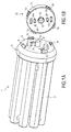
- FIG 1A shows a discharge lamp 1 with a tubular discharge vessel 2 containing, not illustrated, electrodes for creating a discharge path.
- the lamp 1 also has a lamp base 3, holding the discharge vessel 2 and the electrodes, with a central projection 4 that points away from the discharge vessel 2.
- the projection 4 is surrounded by a base surface 5 with peripheral coupling hooks 6 (also referred to as lock engaging portions 6).
- the base 3 also holds contact pins 7 (also referred to as contact organs 7) in a parallel orientation to the projection 4 and also pointing away from the discharge vessel 2. Key slits 8 in the projection 4 will be explained with reference to figure 2.
- the lamp base 3 also has catches 9 that are resilient connected to the base surface 5.
- the contact pins 7 have to be brought in contact with a power supply. Another demand for successful operation of the lamp 1 is that its position is controlled.
- a lamp holder 10 as showed in figure 1B can provide both of these functions.
- the lamp holder 10 has a holder surface 11 with a central aperture 12 that can hold the projection 4 of the lamp 1.
- In the aperture 12 are key notches 13 to be explained in relation to figure 2.
- the holder surface 11 of the lamp holder 10 also has slot like openings 14 to cooperate with the contact pins 7 of the lamp 1 that enable the pins 7 to be moved after they are inserted in the openings 14 into counter contact organs.
- On the periphery of the holder surface 11 are protrusions 15 to be hold by the coupling hooks 6 of the lamp 1.
- the lamp 1 After insertion of the projection 4 in the aperture 12 and the pins 7 in the openings 14 the lamp 1 can be rotated relative to the lamp holder 10 around the axis of the projection 4. This will make the coupling hooks 6 to cooperate with the protrusions 15 and thus coupling the lamp 1 and the lamp holder 10.
- the catches 9 on the lamp 1 that during the insertion of the lamp 1 in the lamp holders are forced back to positions at the level of the base surface 5 can take their original positions when they reach holes 16 for this purpose provided in the holder surface 11.
- the catches 9 are located in the base 3 as the resilient connection can wear in time.
- the base 3 however will be changed at the end of lifetime of the lamp 1 and thus will also the catches, being a part of the lamp 1, be changed.
- the cooperation of the catches 9 and the holes 16 will result in an stop of the coupling of lamp 1 and lamp holder 10 giving a "feeling" that the lamp is correctly mounted and that provides a resistance against loosening, for instance due to vibrations.
- the resilient catches 9 can be made of plastic without the need for metal springs.
- An additional stop function can be provided by side walls of the coupling hooks 6 in cooperation with the protrusions of the holder surface 11.
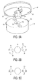
- FIG 2A shows a combination lamp base 20 and lamp holder 21 according the invention.
- the lamp holder 21 in this figure has only two coupling hooks 22 and the lamp holder 21 has only two protrusions 23. This however does not change the way of coupling lamp base 20 and lamp holder 21 relative to the coupling of the lamp 1 and the lamp holder 10 as showed in figures 1A and 1B.
- Protrusion 24 of the lamp base 20 has a key slit 25 with a chamber 26 on the side of the slit 25 that is close to the base surface 27.
- the protrusion 24 can only be inserted in aperture 28 of the lamp holder 21 when a key notch 29 (or nose 29) that is located in the aperture 28 fits in the key slit 25.
- the chamber 26 After substantial insertion of the protrusion 24 in the aperture 28 the chamber 26 will reach the notch 29 enabling the lamp base 20 to be rotated relative to the lamp holder 21.
- the coupling can only be successful positioning of the slit 25, chamber 26 and notch 29 is in harmony. When the slit 25, chamber 26 and notch 29 are not tuned the coupling will be prevented thus providing a security against undesired couplings of lamp bases 20 and lamp holders 21.
- FIG 2B a partial top view on contact pins 30 and receiving organs 31 is showed in a position in which the protrusion 24 is inserted in the aperture 28 (see figure 2A) before the contact pins 30 are turned to their contact position or after the contact pins 30 are turned out of their contact position.
- Figure 2C shows the contact pins 30 and the receiving organs 31 in an contact position. The contact pins 30 and receiving organs 31 now cooperate so the pins 30 could be in a contact position with a power source (not illustrated).
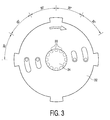
- FIG 3 shows a top view of a lamp holder 32 according the invention with indication of various optional positions of notches 33 (indicated by broken lines) located in a central aperture 34.
- the lamp holder 32 can cooperate with a lamp that is provided with key slits (see figures 1A and 2A) on corresponding positions.
Landscapes
- Engineering & Computer Science (AREA)
- General Engineering & Computer Science (AREA)
- Fastening Of Light Sources Or Lamp Holders (AREA)
- Non-Portable Lighting Devices Or Systems Thereof (AREA)
- Fixing For Electrophotography (AREA)
Abstract
The invention relates to a lamp (1) including a lamp bulb and a lamp
base (3), which lamp base comprises a projection (4) at a substantially
central position of the lamp base (3) in a direction opposite to the
lamp bulb, at least one lock-engaging portion (6), and a substantially
flat base surface (5) opposite to the lamp bulb surrounding the
projection (4), characterized in that, the at least one lock-engaging
portion (6) is located on the edge of the base surface (5) surrounding
the projection (4) distant from the central projection.
The invention also relates to a lamp holder (10) for cooperation with
the lamp (1) according the invention, the lamp holder (10) comprising
an aperture (12) at a substantially central position of the lamp holder,
at least one counter lock-engaging portion (15), and a substantially flat
holder surface surrounding the aperture, characterized in that, the at
least one counter lock-engaging portion (15) is located on the edge of
the holder surface surrounding the aperture distant from the central
aperture.
Description
The invention relates to a lamp including a lamp bulb and a lamp base, which
lamp base comprises a projection at a substantially central position of the lamp base in a
direction opposite to the lamp bulb, at least one lock-engaging portion, and a substantially
flat base surface opposite to the lamp bulb surrounding the projection. The invention also
relates to a lamp holder for cooperation with the lamp according the invention, the lamp
holder comprising an aperture at a substantially central position of the lamp holder, at least
one counter lock-engaging portion, and a substantially flat holder surface surrounding the
aperture.
The US patent 5,746,615 discloses a lighting device, especially used for
discharge lighting, with a base that is disposed at one end of a bulb, and a single end lamp
socket into which the base is to be inserted and then twisted to be rotatively engaged with the
socket. The lamp has a projection and a lamp pin both projected from a bottom of the base.
The socket has a recess into which the projection of the lamp is inserted and rotated by a
predetermined angle. The lighting device is effectively used and has the advantage of easy
exchange of bulbs. However a disadvantage of the lighting device according the US patent is
that a bulb is not always to be positioned the same in the lamp socket giving less optimal use
of luminaries and/or less aesthetic positioning of light sources.
It is an object of the invention to provide a lamp and a lamp holder suited for
simple exchange of lamps but also providing a solid and well defined positioning of the lamp.
A further object of the present invention is to delimit the height of the lamp in the situation
the lamp and lamp holder are coupled.
According the invention a lamp including a lamp bulb and a lamp base of the
type described in the opening paragraph is characterized in that, the at least one lock-engaging
portion is located on the edge of the base surface surrounding the projection distant
from the central projection. In a preferred embodiment the lamp comprises a plurality of
lock-engaging portions which lock-engaging potions are distributed over the edge of the base
surface distant from the central projection. Locating the at least one lock-engaging portion on
the edge of the base surface distant from the central projection brings the advantage of an
increased stability of the lamp when coupled with the lamp holder also provided by the
present invention. The lamp holder according the invention is of the type described in the
opening paragraph and characterized in that, the at least one counter lock-engaging portion is
located on the edge of the holder surface surrounding the aperture distant from the central
aperture. By cooperation of a lock-engaging portion and a counter lock-engaging portion the
fixation of the lamp and lamp holder is provided by cooperation of these two elements but
also by cooperation of the projection of the lamp and the aperture of the lamp holder and by
cooperation of the base surface and the holder surface. The effect of the distance between
lock-engaging portion / counter lock-engaging portion and the projection / aperture is an
enhanced stability of the coupling relative to the coupling according the prior art wherein
lock-engaging portions, as far as they can be identified, are integrated with the
projection / aperture. When use is made of a plurality of lock-engaging portions and a cooperating
plurality of counter lock-engaging portions in the lamp holder the advantage of an increased
stability will be further enhanced. The base surface and the holder surface can provide a large
reference plane ensuring a good positioning of a lamp in a lamp holder (or the luminary that
contains the lamp holder). The lock-engaging portion on the lamp can comprise a hook
shaped element to cooperate with for instance a slit in the lamp holder. The advantage of
locating the relative fragile hook shaped element on the lamp is that with renewal of a lamp
also the hook shaped element is renewed. The construction of a simple hook shaped element
can be realized out of synthetic material making metal springs for retention forces
superfluous. The lamp according the invention further has the advantage that it can be
constructed with only a limited height; the function of the projection of the lamp is to guide
the lamp and not to lock or couple it to the environment. Due to the fact that the projection
only has one objective it can relative to the prior art have only a limited height making the
whole lamp (in height) relative compact.
The central projection has a cross-section that is preferably parallel to the base
surface surrounding the projection that is substantially circular to cooperate with a preferred
lamp holder that has central aperture with a cross-section parallel to the holder surface
surrounding the aperture that is substantially circular. The in cross section circular shape has
the advantage of, dependent of the dimensions of the projection and aperture, enabling
guidance of the lamp base while the projection is inserted in the aperture and enabling
(continuous) guidance during rotation of the lamp in the lamp holder. The improved guidance
of the lamp during coupling or releasing it makes the process of the coupling / releasing more
controlled thus preventing problems with improper us of the lamp and lamp holder.
In another preferred embodiment the lamp base is provided with key means
for identification of the lamp. The key means can comprise at least one aperture in the central
projection in a direction opposite to the lamp bulb. For cooperation with such a lamp the
invention also provides a preferred embodiment of the lamp holder that is provided with
counter key means for controlled cooperation with a key identified lamp. Such counter key
means can comprise at least one projection in the central aperture. Key and counter key
means can prevent improper use of a combination lamp and lamp holder. So can for instance
be prevented that a high voltage lamp is used in a lamp holder only designed for low voltage
lamps or vice versa. An aperture in the projection and a projection in the aperture have the
advantage that such a construction can be made difficult to be damaged. Another advantage
is that the projection / aperture can prepare the relative location of key and counter key
means.
In yet another preferred embodiment of the lamp the lamp base is provided
with contact organs opposite to the lamp bulb projecting from the base surface opposite to the
lamp bulb surrounding the projection. The contact organs, such as for instance contact pins,
can be placed in a straight line, optionally located on opposite sites of the central projection.
For cooperation with the contact organs the invention also provides a preferred embodiment
of the lamp holder that is provided with counter contact organs below the holder surface,
preferably in a touch proof position, surrounding the aperture. Also the counter contact
organs can be placed in a straight line, for instance on opposite sites of the central aperture.
The contact organs and counter contact organs are to cooperate especially to power the lamp.
Locating contact organs and counter contact organs in line makes the production of lamp and
lamp holder simpler and thus cheaper; the contact organs and counter contact organs are
better accessible to connect them with (lead) wires in the lamp and lamp holder.
Non-limitative embodiments of the invention will now be further explained
with reference to the accompanying drawing, in which:
Figure 1A shows a discharge lamp 1 with a tubular discharge vessel 2
containing, not illustrated, electrodes for creating a discharge path. The lamp 1 also has a
lamp base 3, holding the discharge vessel 2 and the electrodes, with a central projection 4 that
points away from the discharge vessel 2. The projection 4 is surrounded by a base surface 5
with peripheral coupling hooks 6 (also referred to as lock engaging portions 6). The base 3
also holds contact pins 7 (also referred to as contact organs 7) in a parallel orientation to the
projection 4 and also pointing away from the discharge vessel 2. Key slits 8 in the projection
4 will be explained with reference to figure 2. The lamp base 3 also has catches 9 that are
resilient connected to the base surface 5. Although the previous description only refers to
discharge lamps the lamp according the invention can also be an incandescent lamp.
For operation of the lamp 1 the contact pins 7 have to be brought in contact
with a power supply. Another demand for successful operation of the lamp 1 is that its
position is controlled. A lamp holder 10 as showed in figure 1B can provide both of these
functions. The lamp holder 10 has a holder surface 11 with a central aperture 12 that can hold
the projection 4 of the lamp 1. In the aperture 12 are key notches 13 to be explained in
relation to figure 2. The holder surface 11 of the lamp holder 10 also has slot like openings
14 to cooperate with the contact pins 7 of the lamp 1 that enable the pins 7 to be moved after
they are inserted in the openings 14 into counter contact organs. On the periphery of the
holder surface 11 are protrusions 15 to be hold by the coupling hooks 6 of the lamp 1. After
insertion of the projection 4 in the aperture 12 and the pins 7 in the openings 14 the lamp 1
can be rotated relative to the lamp holder 10 around the axis of the projection 4. This will
make the coupling hooks 6 to cooperate with the protrusions 15 and thus coupling the lamp 1
and the lamp holder 10. For even better indicating the optimal relative positions of the lamp 1
and lamp holder 10 the catches 9 on the lamp 1 that during the insertion of the lamp 1 in the
lamp holders are forced back to positions at the level of the base surface 5 can take their
original positions when they reach holes 16 for this purpose provided in the holder surface
11. The catches 9 are located in the base 3 as the resilient connection can wear in time. The
base 3 however will be changed at the end of lifetime of the lamp 1 and thus will also the
catches, being a part of the lamp 1, be changed. The cooperation of the catches 9 and the
holes 16 will result in an stop of the coupling of lamp 1 and lamp holder 10 giving a
"feeling" that the lamp is correctly mounted and that provides a resistance against loosening,
for instance due to vibrations. The resilient catches 9 can be made of plastic without the need
for metal springs. An additional stop function can be provided by side walls of the coupling
hooks 6 in cooperation with the protrusions of the holder surface 11.
Figure 2A shows a combination lamp base 20 and lamp holder 21 according
the invention. The lamp holder 21 in this figure has only two coupling hooks 22 and the lamp
holder 21 has only two protrusions 23. This however does not change the way of coupling
lamp base 20 and lamp holder 21 relative to the coupling of the lamp 1 and the lamp holder
10 as showed in figures 1A and 1B. Protrusion 24 of the lamp base 20 has a key slit 25 with a
chamber 26 on the side of the slit 25 that is close to the base surface 27. The protrusion 24
can only be inserted in aperture 28 of the lamp holder 21 when a key notch 29 (or nose 29)
that is located in the aperture 28 fits in the key slit 25. After substantial insertion of the
protrusion 24 in the aperture 28 the chamber 26 will reach the notch 29 enabling the lamp
base 20 to be rotated relative to the lamp holder 21. The coupling can only be successful
positioning of the slit 25, chamber 26 and notch 29 is in harmony. When the slit 25, chamber
26 and notch 29 are not tuned the coupling will be prevented thus providing a security against
undesired couplings of lamp bases 20 and lamp holders 21.
In figure 2B a partial top view on contact pins 30 and receiving organs 31 is
showed in a position in which the protrusion 24 is inserted in the aperture 28 (see figure 2A)
before the contact pins 30 are turned to their contact position or after the contact pins 30 are
turned out of their contact position. Figure 2C shows the contact pins 30 and the receiving
organs 31 in an contact position. The contact pins 30 and receiving organs 31 now cooperate
so the pins 30 could be in a contact position with a power source (not illustrated).
Finally figure 3 shows a top view of a lamp holder 32 according the invention
with indication of various optional positions of notches 33 (indicated by broken lines) located
in a central aperture 34. Dependent on the position (positions) of the notch (notches) in the
aperture 34 the lamp holder 32 can cooperate with a lamp that is provided with key slits (see
figures 1A and 2A) on corresponding positions.
Claims (17)
- Lamp including a lamp bulb and a lamp base, which lamp base comprises a projection at a substantially central position of the lamp base in a direction opposite to the lamp bulb, at least one lock-engaging portion, and a substantially flat base surface opposite to the lamp bulb surrounding the projection, characterized in that, the at least one lock-engaging portion is located on the edge of the base surface surrounding the projection distant from the central projection.
- Lamp as claimed in claim 1, characterized in that, the lamp comprises a plurality of lock-engaging portions which lock-engaging potions are distributed over the edge of the base surface distant from the central projection.
- Lamp as claimed in claim 1 or claim 2, characterized in that, the central projection has a cross-section parallel to the base surface surrounding the projection that is substantially circular.
- Lamp as claimed in one of the previous claims, characterized in that, the lamp base is provided with key means for identification of the lamp.
- Lamp as claimed in claim 4, characterized in that, the key means comprise at least one aperture in the central projection in a direction opposite to the lamp bulb.
- Lamp as claimed in one of the previous claims, characterized in that, the lamp base is provided with contact organs opposite to the lamp bulb projecting from the base surface opposite to the lamp bulb surrounding the projection
- Lamp as claimed in claim 6, characterized in that, the contact organs are placed in a straight line.
- Lamp as claimed in claim 6 or claim 7, characterized in that, the contact organs are located on opposite sites of the central projection.
- Lamp holder for cooperation with the lamp as claimed in one of the claims 1 - 8, the lamp holder comprising an aperture at a substantially central position of the lamp holder, at least one counter lock-engaging portion, and a substantially flat holder surface surrounding the aperture, characterized in that, the at least one counter lock-engaging portion is located on the edge of the holder surface surrounding the aperture distant from the central aperture.
- Lamp holder as claimed in claim 9, characterized in that, the lamp holder comprises a plurality of counter lock-engaging portions which counter lock-engaging potions are distributed over the edge of the holder surface distant from the central aperture.
- Lamp holder as claimed in claim 9 or claim 10, characterized in that, the central aperture has a cross-section parallel to the holder surface surrounding the aperture that is substantially circular.
- Lamp holder as claimed in one of the claims 9 - 11, characterized in that, the lamp holder is provided with counter key means for controlled cooperation with a key identified lamp.
- Lamp holder as claimed in claim 12, characterized in that, the counter key means comprise at least one projection in the central aperture.
- Lamp holder as claimed in one of the claims 9 - 13, characterized in that, the lamp holder is provided with counter contact organs below the holder surface surrounding the aperture.
- Lamp holder as claimed in claim 14, characterized in that, the counter contact organs are placed in a straight line.
- Lamp holder as claimed in claim 14 or claim 15, characterized in that, the counter contact organs are located on opposite sites of the central aperture.
- Assembly of a lamp as claimed in one of the claims 1 - 8 and a lamp holder as claimed in one of the claims 9 - 16, characterized in that, the projection of the lamp is smaller than the aperture of the lamp holder for cooperation of lamp and lamp holder and the at least one lock-engaging portion is located on the edge of the base surface for cooperation with at least one counter lock-engaging portion located on the edge of the holder surface.
Priority Applications (11)
| Application Number | Priority Date | Filing Date | Title |
|---|---|---|---|
| EP02076200A EP1348902A1 (en) | 2002-03-26 | 2002-03-26 | Lamp and lamp holder with peripheral locking means |
| ES03744935T ES2311719T3 (en) | 2002-03-26 | 2003-03-14 | LAMP AND PROTALAMPARAS WITH PERIPHERAL BLOCKING MEDIA. |
| US10/508,459 US7275854B2 (en) | 2002-03-26 | 2003-03-14 | Lamp and lampholder with peripheral locking means |
| CNB038068745A CN100464114C (en) | 2002-03-26 | 2003-03-14 | Lamp and socket with peripheral locking means |
| KR1020047015181A KR101112464B1 (en) | 2002-03-26 | 2003-03-14 | Lamp and lampholder with peripheral locking means |
| AT03744935T ATE405793T1 (en) | 2002-03-26 | 2003-03-14 | LAMP AND LAMP HOLDER WITH COMPREHENSIVE LOCKING MEANS |
| PCT/IB2003/000970 WO2003081126A1 (en) | 2002-03-26 | 2003-03-14 | Lamp and lampholder with peripheral locking means |
| EP03744935A EP1495259B1 (en) | 2002-03-26 | 2003-03-14 | Lamp and lampholder with peripheral locking means |
| JP2003578817A JP4230923B2 (en) | 2002-03-26 | 2003-03-14 | Lamp holder with lamp and locking means around it |
| AU2003209578A AU2003209578A1 (en) | 2002-03-26 | 2003-03-14 | Lamp and lampholder with peripheral locking means |
| DE60323073T DE60323073D1 (en) | 2002-03-26 | 2003-03-14 | LAMP AND LAMP HOLDER WITH SIZE LOCKING |
Applications Claiming Priority (1)
| Application Number | Priority Date | Filing Date | Title |
|---|---|---|---|
| EP02076200A EP1348902A1 (en) | 2002-03-26 | 2002-03-26 | Lamp and lamp holder with peripheral locking means |
Publications (1)
| Publication Number | Publication Date |
|---|---|
| EP1348902A1 true EP1348902A1 (en) | 2003-10-01 |
Family
ID=27798885
Family Applications (2)
| Application Number | Title | Priority Date | Filing Date |
|---|---|---|---|
| EP02076200A Withdrawn EP1348902A1 (en) | 2002-03-26 | 2002-03-26 | Lamp and lamp holder with peripheral locking means |
| EP03744935A Expired - Lifetime EP1495259B1 (en) | 2002-03-26 | 2003-03-14 | Lamp and lampholder with peripheral locking means |
Family Applications After (1)
| Application Number | Title | Priority Date | Filing Date |
|---|---|---|---|
| EP03744935A Expired - Lifetime EP1495259B1 (en) | 2002-03-26 | 2003-03-14 | Lamp and lampholder with peripheral locking means |
Country Status (10)
| Country | Link |
|---|---|
| US (1) | US7275854B2 (en) |
| EP (2) | EP1348902A1 (en) |
| JP (1) | JP4230923B2 (en) |
| KR (1) | KR101112464B1 (en) |
| CN (1) | CN100464114C (en) |
| AT (1) | ATE405793T1 (en) |
| AU (1) | AU2003209578A1 (en) |
| DE (1) | DE60323073D1 (en) |
| ES (1) | ES2311719T3 (en) |
| WO (1) | WO2003081126A1 (en) |
Cited By (7)
| Publication number | Priority date | Publication date | Assignee | Title |
|---|---|---|---|---|
| NL1026188C2 (en) * | 2004-05-13 | 2005-11-15 | Massimo Perra | Assembly and method for releasable mechanical and electrical coupling of an electrical device. |
| DE102008008809B3 (en) * | 2008-02-12 | 2009-04-30 | Bjb Gmbh & Co.Kg | Lamp i.e. compact fluorescent lamp, arrangement device for illuminating space, has lamp holder inserted into lamp socket when illumination specified by base key does not exceed maximally permissible illumination defined by socket key |
| WO2009100699A1 (en) * | 2008-02-12 | 2009-08-20 | Bjb Gmbh & Co. Kg | Device for the arrangement in particular of a compact fluorescent lamp |
| WO2009112391A1 (en) * | 2008-03-04 | 2009-09-17 | Osram Gesellschaft mit beschränkter Haftung | Base/socket system for lamps |
| EP2662938A1 (en) * | 2012-05-09 | 2013-11-13 | ATG R&D Limited | Electrically isolating lamp assembly |
| US20160312996A1 (en) * | 2013-11-29 | 2016-10-27 | Panasonic Ecology Systems Guangdong Co., Ltd. | Ventilation illumination device |
| EP3141813A1 (en) * | 2015-03-30 | 2017-03-15 | Marco Brunner | Lighting body as modular, configurable and controllable led light |
Families Citing this family (22)
| Publication number | Priority date | Publication date | Assignee | Title |
|---|---|---|---|---|
| EP1190439B1 (en) * | 1999-12-17 | 2007-08-08 | Koninklijke Philips Electronics N.V. | Lamp cap, assembly of lamp burner and lamp cap, and method of fastening a lamp |
| US20080227320A1 (en) * | 2003-01-15 | 2008-09-18 | Witham David L | Lamp keying system and method |
| CN101111712B (en) * | 2005-02-02 | 2015-07-29 | 皇家飞利浦电子股份有限公司 | Light source module and its support |
| JP4600135B2 (en) * | 2005-04-25 | 2010-12-15 | パナソニック電工株式会社 | lighting equipment |
| JP2007080678A (en) * | 2005-09-14 | 2007-03-29 | Matsushita Electric Ind Co Ltd | Metal vapor discharge lamp, lamp socket, and lighting device |
| JP2008053058A (en) * | 2006-08-24 | 2008-03-06 | Nec Lighting Ltd | GX53 socket compatible lamp adapter |
| WO2008039454A2 (en) * | 2006-09-25 | 2008-04-03 | Lightsources Inc. | Smooth action, spring loaded, twist locking, radial lugged safety connector for lamp |
| NZ555021A (en) * | 2007-05-07 | 2009-11-27 | Intellectual Property Energy M | A light assembly |
| US7641517B2 (en) * | 2008-02-12 | 2010-01-05 | Bjb Gmbh & Co. Kg | Keyed socket and lamp base |
| EP2286490B1 (en) * | 2008-06-12 | 2016-04-20 | Light Sources, Inc. | End cap, socket, and adaptors for use with a lamp |
| BRPI0914048B1 (en) * | 2008-10-14 | 2019-04-09 | Philips Lighting Holding B.V. | SYSTEM FOR REMOVABLELY CONNECTING A FIRST MEMBER TO A SECOND MEMBER, LED LAMP FOR USE IN A SYSTEM AND SOCKET FOR USE IN A SYSTEM |
| TWM366638U (en) * | 2009-02-27 | 2009-10-11 | Energyled Corp | Rotatable LED lamp tube connector |
| JP5796204B2 (en) * | 2010-12-21 | 2015-10-21 | パナソニックIpマネジメント株式会社 | Lamp socket |
| CN202152934U (en) * | 2011-04-22 | 2012-02-29 | 比亚迪股份有限公司 | Rotatable lamp |
| TW201414950A (en) * | 2012-10-05 | 2014-04-16 | Lextar Electronics Corp | End cap of lamp |
| JP6021593B2 (en) | 2012-11-07 | 2016-11-09 | 矢崎総業株式会社 | connector |
| KR20150033234A (en) * | 2013-09-24 | 2015-04-01 | 엘지이노텍 주식회사 | Lighting device |
| CN105276535A (en) * | 2014-06-06 | 2016-01-27 | 欧普照明股份有限公司 | Switching component |
| CN108072023B (en) * | 2016-11-18 | 2021-09-07 | 朗德万斯公司 | End cap for a lamp tube, lamp tube and method for mounting a lamp tube |
| TWI656301B (en) * | 2017-03-20 | 2019-04-11 | 仁寶電腦工業股份有限公司 | Electronic device |
| CN216013912U (en) * | 2021-07-08 | 2022-03-11 | 深圳市爱图仕影像器材有限公司 | Clamping structure and lighting equipment with same |
| CN117006444A (en) * | 2023-08-09 | 2023-11-07 | 宁波晶辉光电有限公司 | Handheld working lamp |
Citations (2)
| Publication number | Priority date | Publication date | Assignee | Title |
|---|---|---|---|---|
| US5746615A (en) * | 1995-07-17 | 1998-05-05 | Matsushita Electric Works, Ltd. | Lighting device |
| EP0935092A1 (en) * | 1998-02-03 | 1999-08-11 | General Electric Company | Low-pressure discharge lamp and lampholder thereof |
Family Cites Families (9)
| Publication number | Priority date | Publication date | Assignee | Title |
|---|---|---|---|---|
| CN2118891U (en) * | 1991-12-12 | 1992-10-14 | 庄文德 | Small decorative lamp with swivel structure |
| US5428516A (en) * | 1994-02-28 | 1995-06-27 | Harris; Geoffrey H. | Interlock for miniature lamp arrays |
| CN2219423Y (en) * | 1994-04-01 | 1996-02-07 | 上海宇宙霓虹有限公司 | Combined lamp holder |
| US5585688A (en) * | 1994-11-28 | 1996-12-17 | Prolight | Compact fluorescent lamp |
| CN2251663Y (en) * | 1995-01-27 | 1997-04-09 | 童国钧 | Bulb assemblies for decorative lighting sets |
| JPH10106704A (en) * | 1996-09-30 | 1998-04-24 | Toshiba Lighting & Technol Corp | Lamp device and display device |
| JP3032499B2 (en) | 1998-02-05 | 2000-04-17 | 三陽工業株式会社 | Electromagnetic braking device |
| CN2443232Y (en) * | 2000-09-04 | 2001-08-15 | 刘朝惠 | Work light base with improved structure |
| US6779911B2 (en) * | 2002-11-26 | 2004-08-24 | Rhine Electronic Co., Ltd. | Separation device of a lamp holder and a fixing seat |
-
2002
- 2002-03-26 EP EP02076200A patent/EP1348902A1/en not_active Withdrawn
-
2003
- 2003-03-14 JP JP2003578817A patent/JP4230923B2/en not_active Expired - Fee Related
- 2003-03-14 DE DE60323073T patent/DE60323073D1/en not_active Expired - Lifetime
- 2003-03-14 CN CNB038068745A patent/CN100464114C/en not_active Expired - Fee Related
- 2003-03-14 US US10/508,459 patent/US7275854B2/en not_active Expired - Fee Related
- 2003-03-14 AT AT03744935T patent/ATE405793T1/en not_active IP Right Cessation
- 2003-03-14 KR KR1020047015181A patent/KR101112464B1/en not_active Expired - Fee Related
- 2003-03-14 EP EP03744935A patent/EP1495259B1/en not_active Expired - Lifetime
- 2003-03-14 ES ES03744935T patent/ES2311719T3/en not_active Expired - Lifetime
- 2003-03-14 AU AU2003209578A patent/AU2003209578A1/en not_active Abandoned
- 2003-03-14 WO PCT/IB2003/000970 patent/WO2003081126A1/en not_active Ceased
Patent Citations (2)
| Publication number | Priority date | Publication date | Assignee | Title |
|---|---|---|---|---|
| US5746615A (en) * | 1995-07-17 | 1998-05-05 | Matsushita Electric Works, Ltd. | Lighting device |
| EP0935092A1 (en) * | 1998-02-03 | 1999-08-11 | General Electric Company | Low-pressure discharge lamp and lampholder thereof |
Cited By (9)
| Publication number | Priority date | Publication date | Assignee | Title |
|---|---|---|---|---|
| NL1026188C2 (en) * | 2004-05-13 | 2005-11-15 | Massimo Perra | Assembly and method for releasable mechanical and electrical coupling of an electrical device. |
| DE102008008809B3 (en) * | 2008-02-12 | 2009-04-30 | Bjb Gmbh & Co.Kg | Lamp i.e. compact fluorescent lamp, arrangement device for illuminating space, has lamp holder inserted into lamp socket when illumination specified by base key does not exceed maximally permissible illumination defined by socket key |
| WO2009100699A1 (en) * | 2008-02-12 | 2009-08-20 | Bjb Gmbh & Co. Kg | Device for the arrangement in particular of a compact fluorescent lamp |
| WO2009112391A1 (en) * | 2008-03-04 | 2009-09-17 | Osram Gesellschaft mit beschränkter Haftung | Base/socket system for lamps |
| EP2662938A1 (en) * | 2012-05-09 | 2013-11-13 | ATG R&D Limited | Electrically isolating lamp assembly |
| US8876359B2 (en) | 2012-05-09 | 2014-11-04 | Atg R&D Limited | Electrically isolating lamp assembly |
| US20160312996A1 (en) * | 2013-11-29 | 2016-10-27 | Panasonic Ecology Systems Guangdong Co., Ltd. | Ventilation illumination device |
| US10274191B2 (en) * | 2013-11-29 | 2019-04-30 | Panasonic Ecology Systems Guangdong Co., Ltd. | Ventilation illumination device |
| EP3141813A1 (en) * | 2015-03-30 | 2017-03-15 | Marco Brunner | Lighting body as modular, configurable and controllable led light |
Also Published As
| Publication number | Publication date |
|---|---|
| US7275854B2 (en) | 2007-10-02 |
| ATE405793T1 (en) | 2008-09-15 |
| DE60323073D1 (en) | 2008-10-02 |
| KR20040108690A (en) | 2004-12-24 |
| CN100464114C (en) | 2009-02-25 |
| CN1643300A (en) | 2005-07-20 |
| JP4230923B2 (en) | 2009-02-25 |
| US20050174765A1 (en) | 2005-08-11 |
| JP2005521213A (en) | 2005-07-14 |
| AU2003209578A1 (en) | 2003-10-08 |
| KR101112464B1 (en) | 2012-02-22 |
| WO2003081126A1 (en) | 2003-10-02 |
| EP1495259A1 (en) | 2005-01-12 |
| ES2311719T3 (en) | 2009-02-16 |
| EP1495259B1 (en) | 2008-08-20 |
Similar Documents
| Publication | Publication Date | Title |
|---|---|---|
| EP1348902A1 (en) | Lamp and lamp holder with peripheral locking means | |
| US7641517B2 (en) | Keyed socket and lamp base | |
| US5795192A (en) | Socket for receiving a radiation source and a radiation source with a base | |
| JP5616765B2 (en) | Lamp socket and lighting apparatus using the same | |
| US2160786A (en) | Tubular lamp base | |
| WO2012043585A1 (en) | Socket and lighting device | |
| CN101889169B (en) | Devices for setting especially compact fluorescent lamps | |
| US2241065A (en) | Lamp socket | |
| JP5440800B2 (en) | socket | |
| CN109937324B (en) | Lighting arrangement with replaceable lighting cap | |
| JPS645831Y2 (en) | ||
| JP2004172065A (en) | Lamp sockets and lighting equipment | |
| JP5769034B2 (en) | Socket and lighting device | |
| JP5445786B2 (en) | socket | |
| JP2011216285A (en) | Lighting fixture | |
| KR200346985Y1 (en) | Socket for fluorescent lamp | |
| CN209371166U (en) | Lamp holder | |
| JPH1153917A (en) | Lamp holder, lamp holder mounting device, light control device, and lighting device | |
| JP2018129216A (en) | Fall prevention fixture | |
| JP6021179B2 (en) | Socket, socket cover and lighting device | |
| US4561713A (en) | Lamp socket bracket system | |
| JPH0129688Y2 (en) | ||
| JPS6310571Y2 (en) | ||
| JP5700231B2 (en) | Socket and lighting device | |
| JPH11250722A (en) | Luminaire |
Legal Events
| Date | Code | Title | Description |
|---|---|---|---|
| PUAI | Public reference made under article 153(3) epc to a published international application that has entered the european phase |
Free format text: ORIGINAL CODE: 0009012 |
|
| AK | Designated contracting states |
Kind code of ref document: A1 Designated state(s): AT BE CH CY DE DK ES FI FR GB GR IE IT LI LU MC NL PT SE TR |
|
| AX | Request for extension of the european patent |
Extension state: AL LT LV MK RO SI |
|
| STAA | Information on the status of an ep patent application or granted ep patent |
Free format text: STATUS: THE APPLICATION IS DEEMED TO BE WITHDRAWN |
|
| 18D | Application deemed to be withdrawn |
Effective date: 20030727 |