EP1349340A2 - Method for controlling a home appliance networking system - Google Patents
Method for controlling a home appliance networking system Download PDFInfo
- Publication number
- EP1349340A2 EP1349340A2 EP02025643A EP02025643A EP1349340A2 EP 1349340 A2 EP1349340 A2 EP 1349340A2 EP 02025643 A EP02025643 A EP 02025643A EP 02025643 A EP02025643 A EP 02025643A EP 1349340 A2 EP1349340 A2 EP 1349340A2
- Authority
- EP
- European Patent Office
- Prior art keywords
- home
- networking system
- home appliance
- internal network
- home appliances
- Prior art date
- Legal status (The legal status is an assumption and is not a legal conclusion. Google has not performed a legal analysis and makes no representation as to the accuracy of the status listed.)
- Granted
Links
- 230000006855 networking Effects 0.000 title claims abstract description 74
- 238000000034 method Methods 0.000 title claims abstract description 14
- 238000004891 communication Methods 0.000 claims abstract description 49
- 230000004044 response Effects 0.000 claims description 8
- 238000013500 data storage Methods 0.000 claims description 7
- 230000005540 biological transmission Effects 0.000 claims description 3
- 238000010276 construction Methods 0.000 description 5
- 238000010586 diagram Methods 0.000 description 4
- 230000006870 function Effects 0.000 description 4
- 238000004519 manufacturing process Methods 0.000 description 3
- 238000009434 installation Methods 0.000 description 2
- 238000007726 management method Methods 0.000 description 2
- 238000007792 addition Methods 0.000 description 1
- 230000002349 favourable effect Effects 0.000 description 1
- 238000012986 modification Methods 0.000 description 1
- 230000004048 modification Effects 0.000 description 1
- 238000012545 processing Methods 0.000 description 1
- 238000006467 substitution reaction Methods 0.000 description 1
Images


Classifications
-
- H—ELECTRICITY
- H04—ELECTRIC COMMUNICATION TECHNIQUE
- H04L—TRANSMISSION OF DIGITAL INFORMATION, e.g. TELEGRAPHIC COMMUNICATION
- H04L12/00—Data switching networks
- H04L12/28—Data switching networks characterised by path configuration, e.g. LAN [Local Area Networks] or WAN [Wide Area Networks]
-
- H—ELECTRICITY
- H04—ELECTRIC COMMUNICATION TECHNIQUE
- H04L—TRANSMISSION OF DIGITAL INFORMATION, e.g. TELEGRAPHIC COMMUNICATION
- H04L12/00—Data switching networks
- H04L12/28—Data switching networks characterised by path configuration, e.g. LAN [Local Area Networks] or WAN [Wide Area Networks]
- H04L12/2803—Home automation networks
-
- H—ELECTRICITY
- H04—ELECTRIC COMMUNICATION TECHNIQUE
- H04L—TRANSMISSION OF DIGITAL INFORMATION, e.g. TELEGRAPHIC COMMUNICATION
- H04L12/00—Data switching networks
- H04L12/28—Data switching networks characterised by path configuration, e.g. LAN [Local Area Networks] or WAN [Wide Area Networks]
- H04L12/2803—Home automation networks
- H04L12/2816—Controlling appliance services of a home automation network by calling their functionalities
- H04L12/2818—Controlling appliance services of a home automation network by calling their functionalities from a device located outside both the home and the home network
-
- H—ELECTRICITY
- H04—ELECTRIC COMMUNICATION TECHNIQUE
- H04L—TRANSMISSION OF DIGITAL INFORMATION, e.g. TELEGRAPHIC COMMUNICATION
- H04L61/00—Network arrangements, protocols or services for addressing or naming
-
- H—ELECTRICITY
- H04—ELECTRIC COMMUNICATION TECHNIQUE
- H04L—TRANSMISSION OF DIGITAL INFORMATION, e.g. TELEGRAPHIC COMMUNICATION
- H04L61/00—Network arrangements, protocols or services for addressing or naming
- H04L61/50—Address allocation
-
- H—ELECTRICITY
- H04—ELECTRIC COMMUNICATION TECHNIQUE
- H04L—TRANSMISSION OF DIGITAL INFORMATION, e.g. TELEGRAPHIC COMMUNICATION
- H04L67/00—Network arrangements or protocols for supporting network services or applications
- H04L67/01—Protocols
- H04L67/04—Protocols specially adapted for terminals or networks with limited capabilities; specially adapted for terminal portability
-
- H—ELECTRICITY
- H04—ELECTRIC COMMUNICATION TECHNIQUE
- H04L—TRANSMISSION OF DIGITAL INFORMATION, e.g. TELEGRAPHIC COMMUNICATION
- H04L67/00—Network arrangements or protocols for supporting network services or applications
- H04L67/01—Protocols
- H04L67/06—Protocols specially adapted for file transfer, e.g. file transfer protocol [FTP]
-
- H—ELECTRICITY
- H04—ELECTRIC COMMUNICATION TECHNIQUE
- H04L—TRANSMISSION OF DIGITAL INFORMATION, e.g. TELEGRAPHIC COMMUNICATION
- H04L67/00—Network arrangements or protocols for supporting network services or applications
- H04L67/50—Network services
- H04L67/60—Scheduling or organising the servicing of application requests, e.g. requests for application data transmissions using the analysis and optimisation of the required network resources
- H04L67/62—Establishing a time schedule for servicing the requests
Definitions
- the present invention relates to home appliance networking systems and methods for controlling the same, and more particularly to a home appliance networking system and a method for controlling the same, wherein private Internet protocol (IP) addresses or port numbers are assigned respectively to a plurality of home appliances in a home networking system so that the home appliances can transmit and receive data to/from a network through the assigned private IP addresses or port numbers, thereby making it possible to construct the home networking system in a simpler manner and curtail costs required for the system construction.
- IP Internet protocol
- a home appliance networking system has recently been highlighted in which a plurality of home appliances are interconnected via an internal network of a home and the internal network is connected to an external Internet network, thereby enabling a user to control the home appliances from anywhere inside and outside of the home.
- the user can not only recognize state information of a specific home appliance at any place inside of the home, but also control the specific home appliance through the use of control means, such as a computer, at any place outside of the home.
- control means such as a computer
- the above-mentioned home appliance networking system has a disadvantage in that a local area network (LAN) must be constructed in the home or building to interconnect the home appliances via the internal network of the home and control the interconnected appliances in an integrated manner, resulting in a great cost being incurred.
- LAN local area network
- a high-price LAN card and a communication processable central processing unit (CPU) of the personal computer (PC) class must be installed in each of the home appliances.
- the present invention has been made in view of the above problems, and it is an object of the present invention to provide a home appliance networking system and a method for controlling the same, wherein an IP sharing unit is provided to assign private IP addresses or port numbers respectively to a plurality of home appliances in a home networking system, and a plurality of communication processors are provided to enable corresponding ones of the home appliances to transmit and receive data to/from a network through the private IP addresses or port numbers assigned by the IP sharing unit, thereby making it possible to operate the home networking system more simply and efficiently.
- a home appliance networking system comprising: networking means for connecting an internal network of a home networking system to an external network of the home networking system; Internet protocol (IP) sharing means assigned a public IP address for enabling a user to gain access to the home networking system from the external network; and a plurality of communication processors connected respectively to product controllers of a plurality of home appliances for enabling corresponding ones of the home appliances to be assigned private IP addresses or port numbers from the IP sharing means and transmit and receive data to/from the internal network using the assigned private IP addresses or port numbers, respectively.
- IP Internet protocol
- a method for controlling a home appliance networking system comprising the steps of: a) assigning a public IP address to IP sharing means, the IP sharing means assigning private IP addresses or port numbers respectively to a plurality of home appliances connected to an internal network of a home networking system; b) connecting a computing device to the IP sharing means to allow the computing device to input a control command to a specific one of the plurality of home appliances connected to the internal network; c) connecting the IP sharing means to the plurality of home appliances connected to the internal network as the computing device is connected to the IP sharing means at the step b); d) inputting the control command through the computing device to the plurality of home appliances with the private IP addresses or port numbers assigned by the IP sharing means connected at the step c); and e) controlling a corresponding one of the home appliances in response to the control command inputted at the step d).
- the home appliance networking system comprises an existing LAN L1, which is an internal network of a home networking system constructed in a home or building, networking equipment for connecting the internal network of the home networking system to an external network of the home networking system, an IP sharing unit 10 assigned a public IP address for enabling a user to gain access to the internal network from the external network through the networking equipment, and a plurality of communication processors T1-Tn connected respectively to product controllers C1-Cn of a plurality of home appliances H1-Hn for enabling corresponding ones of the home appliances to be assigned private IP addresses from the IP sharing unit 10 and transmit and receive data to/from the internal network using the assigned private IP addresses, respectively.
- an existing LAN L1 is an internal network of a home networking system constructed in a home or building
- networking equipment for connecting the internal network of the home networking system to an external network of the home networking system
- an IP sharing unit 10 assigned a public IP address for enabling a user to gain access to the internal network from the external network through the networking equipment
- the IP sharing unit 10 preferably sets and assigns unique private IP addresses respectively to the plurality of home appliances H1-Hn. Alternatively, the IP sharing unit 10 may assign the same private IP addresses with different port numbers respectively to the plurality of home appliances H1-Hn. Further, the IP sharing unit 10 preferably maps the private IP addresses or port numbers assigned respectively to the plurality of home appliances H1-Hn, to the home appliances H1-Hn and stores the resulting map information. As a result, a control command from the external network is transmitted to a private IP address or port number of a corresponding home appliance on the basis of the map information stored in the IP sharing unit 10.
- the private IP addresses or port numbers assigned respectively to the home appliances by the IP sharing unit 10 are stored respectively in the plurality of communication processors T1-Tn connected respectively to the product controllers of the home appliances. After storing the private IP addresses or port numbers assigned by the IP sharing unit 10, the communication processors T1-Tn send only data associated with the corresponding home appliances with the stored private IP addresses or port numbers to the product controllers C1-Cn, respectively. Thus, the plurality of home appliances H1-Hn are controllable according to only the associated data.
- the networking equipment includes a gateway G acting as an ingress of the internal network of the home networking system, and a hub H for receiving data from the external network via the gateway G, sending the received data to the IP sharing unit 10, receiving data from the IP sharing unit 10 and sending the received data to the external network via the gateway G.
- the IP sharing unit 10 and the plurality of home appliances H1-Hn are connected to the existing LAN in such a manner that an internal data line to the internal network and an external data line to the external network are physically interconnected via the IP sharing unit 10.
- data transmitted and received via the IP sharing unit 10 must be passed through the IP sharing unit 10 as shown in Fig. 1.
- the IP sharing unit 10 may transmit and receive data over an internal network, which is a newly constructed LAN L2 as shown in Fig. 2, not the existing LAN L1.
- the internal data line to the internal network and the external data line to the external network are separated from each other on the IP sharing unit 10 as shown in Fig. 2.
- the IP sharing unit 10 has a public IP address assigned thereto, and sets and assigns private IP addresses or port numbers to the plurality of home appliances H1-Hn.
- the IP sharing unit 10 is further adapted to assign the private IP addresses or port numbers to the plurality of home appliances H1-Hn and control the flow of data to the assigned private IP addresses or port numbers. Therefore, the home networking system is controllable through the IP sharing unit 10.
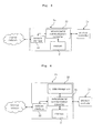
- Fig. 3 shows an internal structure of a first-type communication processor in the home appliance networking system in accordance with the present invention, namely, the communication processor Tn connected to the product controller Cn of the nth one Hn of the plurality of home appliances H1-Hn.
- the first-type communication processor Tn includes a network/serial communication converter 20 for converting the format of data appropriately to standards of the internal network and product controller Cn such that the corresponding home appliance Hn transmits and receives the data to/from the internal network, and a memory 21 for storing the private IP address or port number assigned to the corresponding home appliance Hn by the IP sharing unit 10.
- the memory 21 is preferably a read only memory (ROM).
- the first-type communication processor Tn further includes a network interface 22 for transferring data, outputted from the product controller Cn and then format-converted appropriately to the standard of the internal network by the network/serial communication converter 20, to the internal network, and transferring data associated with the corresponding home appliance Hn from the internal network to the network/serial communication converter 20.
- the network/serial communication converter 20 preferably transmits and receives data to/from the product controller Cn in a UART standard-based serial communication manner.
- the network/serial communication converter 20 transmits and receives data to/from the network interface 22 in a network communication manner to transmit and receive the data to/from the internal network.
- data format-converted appropriately to the standard of the internal network by the network/serial communication converter 20 may be transferred directly to the internal network, not via the network interface 22, and data from the internal network may also be transferred directly to the network/serial communication converter 20, not via the network interface 22. That is, the function of the network interface 22 may be included in the network/serial communication converter 20.
- Fig. 4 shows an internal structure of a second-type communication processor in the home appliance networking system in accordance with the present invention, namely, the communication processor T1 connected to the product controller C1 of a specific one, for example, H1 of the plurality of home appliances H1-Hn.
- the second-type communication processor T1 further includes, in addition to the network/serial communication converter 20, memory 21 and network interface 22, a user interface (UI) data storage unit 23 for storing UI data for execution of a UI program appropriate to the control of the plurality of home appliances H1-Hn connected to the internal network.
- UI user interface
- the UI data stored in the UI data storage unit 23 is preferably sent to an external computing device (not shown) which accesses the IP sharing unit 10 over the external network to send control commands to the plurality of home appliances of the home networking system, or to an internal computing device (not shown) which sends control commands to the plurality of home appliances over the internal network.
- the external or internal computing device executes the UI program in response to the UI data sent thereto, so the user can input desired control commands to the plurality of home appliances through the executed UI program using the external or internal computing device.
- the inputted control commands are sent to home appliances with corresponding private IP addresses or port numbers via the IP sharing unit 10.
- the second-type communication processor T1 further includes an internal network controller (not shown) for managing transmission and reception of data over the internal network by the plurality of home appliances.
- the second-type communication processor T1 may also function as network management means for managing transmission and reception of data by the home networking system.
- the home appliance networking system of one home networking system can comprise the second-type communication processor T1 connected to one IP sharing unit 10 and the product controller C1 of one home appliance H1, and the first-type communication processors T2-Tn connected respectively to the product controllers C2-Cn of the other home appliances H2-Hn. Therefore, the UI data storage unit is contained in only one communication processor of the home appliance networking system, which acts as the network management means for performing the function of the internal network controller. Consequently, the home appliance networking system can be efficiently operated with no need to provide the UI data storage unit in a plurality of communication processors or allow them to perform the function of the internal network controller.
- Fig. 5 is a flow chart illustrating a method for controlling the home appliance networking system in accordance with the present invention.
- a computing device attempts a connection to an IP sharing unit assigned a public IP address.
- the computing device sends an identification (ID) and password entered by a user to the IP sharing unit while attempting the connection thereto.
- ID an identification
- password entered by a user
- the IP sharing unit determines whether the ID and password sent from the computing device are the same as a valid ID and valid password stored therein.
- the IP sharing unit sets a private IP address or port number of a home appliance to be connected, among a plurality of home appliances connected to an internal network at the third step S3. Note that the IP sharing unit has previously assigned private IP addresses or port numbers respectively to the plurality of home appliances.
- the IP sharing unit sends a connection command to the home appliance with the private IP address or port number set at the third step S3.
- the IP sharing unit determines whether its connection with the home appliance to which the connection command has been sent at the fourth step S4 has been completed.
- the IP sharing unit determines at the sixth step S6 whether its connection with all the home appliances connected to the internal network has been completed. At this time, because the IP sharing unit stores information regarding the private IP addresses or port numbers of all the home appliances connected to the internal network, it can determine on the basis of the stored information whether its connection with all the home appliances has been completed. On the other hand, if it is determined at the fifth step S5 that the home appliance connection has not been completed, the IP sharing unit returns to the fifth step S5 to again determine whether the home appliance connection has been completed.
- the IP sharing unit increments the private IP address or port number set at the third step S3 by one at the seventh step S7 and then returns to the fourth step S4.
- a second-type communication processor sends, at the eighth step S8, UI data to the computing device that has attempted the connection to the IP sharing unit at the first step S1.
- the computing device executes a UI program in response to the UI data sent thereto.
- the user inputs a control command through the UI program executed by the computing device.
- the computing device sends the control command inputted through the UI program to the IP sharing unit, which then transfers the sent control command to a private IP address or port number of a corresponding home appliance.
- a communication processor of the corresponding home appliance determines whether a private IP address or port number of the control command transferred at the eleventh step S11 is the same as the private IP address or port number of the corresponding home appliance.
- the communication processor of the corresponding home appliance sends the transferred control command to the corresponding home appliance, which is then controlled according to that control command.
- the communication processor of the corresponding home appliance discards the transferred control command.
- the present invention provides a home appliance networking system and a method for controlling the same, wherein an IP sharing unit assigns private IP addresses or port numbers respectively to a plurality of home appliances in a home networking system and is assigned a public IP address so that the home networking system can be accessed from an external network, and a plurality of communication processors are connected respectively to product controllers of the home appliances to store corresponding ones of the private IP addresses or port numbers assigned by the IP sharing unit and enable corresponding ones of the home appliances to transmit and receive data to/from an internal network of the home networking system through the corresponding private IP addresses or port numbers. Therefore, the home appliance networking system can be constructed in a simpler manner and at a lower cost to operate the home networking system efficiently.
Landscapes
- Engineering & Computer Science (AREA)
- Computer Networks & Wireless Communication (AREA)
- Signal Processing (AREA)
- Automation & Control Theory (AREA)
- Small-Scale Networks (AREA)
- Data Exchanges In Wide-Area Networks (AREA)
- Computer And Data Communications (AREA)
- Selective Calling Equipment (AREA)
Abstract
Description
Claims (15)
- A home appliance networking system comprising:networking means for connecting an internal network of a home networking system to an external network of said home networking system;Internet protocol (IP) sharing means assigned a public IP address for enabling a user to gain access to said home networking system from said external network; anda plurality of communication processors connected respectively to product controllers of a plurality of home appliances for enabling corresponding ones of said home appliances to be assigned private IP addresses or port numbers from said IP sharing means and transmit and receive data to/from said internal network using the assigned private IP addresses or port numbers, respectively.
- The home appliance networking system as set forth in claim 1, wherein said networking means includes:a gateway acting as an ingress of said internal network; anda hub for transmitting and receiving data between said gateway and said IP sharing means.
- The home appliance networking system as set forth in claim 1, wherein said communication processors are adapted to continuously exchange data with said product controllers to determine whether said corresponding home appliances are normally operated.
- The home appliance networking system as set forth in claim 1, wherein each of said communication processors includes:a network/serial communication converter for converting a format of data appropriately to standards of said internal network and said product controller of said corresponding home appliance such that said corresponding home appliance transmits and receives the data to/from said internal network; anda memory for storing said private IP address or port number assigned to said corresponding home appliance by said IP sharing means.
- The home appliance networking system as set forth in claim 4, wherein said memory is a read only memory.
- The home appliance networking system as set forth in claim 4, wherein each of said communication processors further includes a network interface for transferring data, outputted from said product controller of said corresponding home appliance and then format-converted appropriately to said standard of said internal network by said network/serial communication converter, to said internal network, and transferring data associated with said corresponding home appliance from said internal network to said network/serial communication converter.
- The home appliance networking system as set forth in claim 6, wherein each of said communication processors further includes an internal network controller for managing transmission and reception of data over said internal network by said plurality of home appliances.
- The home appliance networking system as set forth in claim 6, wherein each of said communication processors further includes a user interface (UI) data storage unit for storing UI data for execution of a UI program appropriate to the control of said plurality of home appliances connected to said internal network.
- The home appliance networking system as set forth in claim 8, wherein said UI data storage unit is adapted to send the stored UI data to an external computing device, said external computing device accessing said IP sharing means over said external network to control said home appliances connected to said internal network, and executing said UI program in response to said UI data sent thereto so that control commands can be inputted through said external computing device.
- The home appliance networking system as set forth in claim 8, wherein said UI data storage unit is adapted to send the stored UI data to an internal computing device, said internal computing device being connected to said internal network to send control commands to said plurality of home appliances, and executing said UI program in response to said UI data sent thereto so that said control commands can be inputted through said internal computing device.
- A method for controlling a home appliance networking system, comprising the steps of:a) assigning a public IP address to IP sharing means, said IP sharing means assigning private IP addresses or port numbers respectively to a plurality of home appliances connected to an internal network of a home networking system;b) connecting a computing device to said IP sharing means to allow said computing device to input a control command to a specific one of said plurality of home appliances connected to said internal network;c) connecting said IP sharing means to said plurality of home appliances connected to said internal network as said computing device is connected to said IP sharing means at said step b);d) inputting said control command through said computing device to said plurality of home appliances with said private IP addresses or port numbers assigned by said IP sharing means connected at said step c); ande) controlling a corresponding one of said home appliances in response to said control command inputted at said step d).
- The method as set forth in claim 11, further comprising the step of:f) allowing said IP sharing means to assign said private IP addresses or port numbers respectively to said plurality of home appliances before said step b) is performed.
- The method as set forth in claim 11, wherein said step b) includes the steps of:b-1) allowing said computing device to access said IP sharing means using said public IP address assigned thereto;b-2) determining whether an identification (ID) and password entered through said computing device while accessing said IP sharing means are valid; andb-3) connecting said computing device to said IP sharing means if it is determined at said step b-2) that the entered ID and password are valid.
- The method as set forth in claim 11, wherein said step c) includes the steps of:c-1) allowing said IP sharing means to set a private IP address or port number of a home appliance to be connected, among said private IP addresses or port numbers assigned to said plurality of home appliances;c-2) connecting said IP sharing means to said home appliance with said private IP address or port number set at said step c-1); andc-3) determining whether said IP sharing means has been connected to all said plurality of home appliances connected to said internal network and, if said IP sharing means has not been connected to all said plurality of home appliances connected to said internal network, incrementing said private IP address or port number set at said step c-1) by one and then returning to said step c-2).
- The method as set forth in claim 11, further comprising, after said step b) and before said step d), the steps of:f) storing UI data for execution of a UI program in a communication processor and sending the stored UI data to said computing device connected at said step b), said UI program being executed to input said control command to said plurality of home appliances, said communication processor transmitting and receiving data between said internal network and said home appliances; andg) allowing said computing device to execute said UI program in response to said UI data sent thereto.
Applications Claiming Priority (2)
| Application Number | Priority Date | Filing Date | Title |
|---|---|---|---|
| KR2002014160 | 2002-03-15 | ||
| KR10-2002-0014160A KR100420526B1 (en) | 2002-03-15 | 2002-03-15 | Home Appliance Network System and Controlling Method for the Same |
Publications (3)
| Publication Number | Publication Date |
|---|---|
| EP1349340A2 true EP1349340A2 (en) | 2003-10-01 |
| EP1349340A3 EP1349340A3 (en) | 2005-07-27 |
| EP1349340B1 EP1349340B1 (en) | 2012-04-11 |
Family
ID=27800683
Family Applications (1)
| Application Number | Title | Priority Date | Filing Date |
|---|---|---|---|
| EP20020025643 Expired - Lifetime EP1349340B1 (en) | 2002-03-15 | 2002-11-19 | Method for controlling a home appliance networking system |
Country Status (5)
| Country | Link |
|---|---|
| US (1) | US20030177268A1 (en) |
| EP (1) | EP1349340B1 (en) |
| JP (2) | JP2003289588A (en) |
| KR (1) | KR100420526B1 (en) |
| CN (1) | CN1327659C (en) |
Cited By (3)
| Publication number | Priority date | Publication date | Assignee | Title |
|---|---|---|---|---|
| EP2110959A1 (en) | 2008-04-18 | 2009-10-21 | Roland Kogler | Communication method for elements that form an electricity distribution network and devices for implementing the method |
| EP2023539A4 (en) * | 2006-05-29 | 2010-04-28 | China Mobile Comm Corp | METHOD FOR ALLOCATING AN ADDRESS TO A DOMESTIC DEVICE OF INTELLIGENT INFORMATION AND SUB-EQUIPMENT IN THE HOME NETWORK |
| CN104283978A (en) * | 2013-07-09 | 2015-01-14 | 施耐德电气(澳大利亚)有限公司 | Equipment control method, system and converter and third-party control system |
Families Citing this family (17)
| Publication number | Priority date | Publication date | Assignee | Title |
|---|---|---|---|---|
| KR100381170B1 (en) * | 2001-07-20 | 2003-04-18 | 엘지전자 주식회사 | Home Appliance Controlling System and Operating Method for the Same |
| KR100482300B1 (en) * | 2002-07-31 | 2005-04-14 | 주식회사 이지브로네트웍스 | Internet service providing system for many small subscribers through LAN and method for providing internet service, using the system |
| CN100346616C (en) * | 2004-03-26 | 2007-10-31 | 联想(北京)有限公司 | Address setting system and address setting method |
| JP4645165B2 (en) * | 2004-11-12 | 2011-03-09 | セイコーエプソン株式会社 | Network device control for network type plug and play |
| US8677420B2 (en) * | 2005-01-31 | 2014-03-18 | Thomson Licensing | Personal monitoring and information apparatus |
| US8533253B2 (en) * | 2005-06-09 | 2013-09-10 | Whirlpool Corporation | Distributed object-oriented appliance control system |
| EP2228969B1 (en) * | 2005-06-09 | 2017-04-19 | Whirlpool Corporation | Software architecture system and method for communication with, and management of, at least one component within a household appliance |
| US8156256B2 (en) | 2007-04-24 | 2012-04-10 | Samsung Electronics Co., Ltd. | Method for managing logical address and device thereof |
| US20120331156A1 (en) * | 2011-06-21 | 2012-12-27 | Colpitts Cameron | Wireless control system, methods and apparatus |
| CN102692898A (en) * | 2012-05-08 | 2012-09-26 | 夏洋 | Method, device, and system for controlling electrical appliance |
| EP2884698A1 (en) * | 2013-12-16 | 2015-06-17 | Gemalto M2M GmbH | Method for interaction of a device appliance and a communication unit |
| DE102014004793A1 (en) * | 2014-04-02 | 2015-10-08 | Brightup Gmbh | Method and system for assigning a generic device to a user |
| CN105375924A (en) * | 2014-08-26 | 2016-03-02 | 湖北元嘉科技有限公司 | Household electrical appliance signal converter |
| CN105896190A (en) * | 2014-08-26 | 2016-08-24 | 湖北元嘉科技有限公司 | Signal enhancement socket for household electrical appliances |
| CN105846858A (en) * | 2016-05-18 | 2016-08-10 | 珠海格力电器股份有限公司 | Multi-connected air conditioning unit and networking method and device thereof |
| JP7261992B2 (en) * | 2017-10-31 | 2023-04-21 | パナソニックIpマネジメント株式会社 | COMMUNICATION DEVICE, COMMUNICATION SYSTEM, EQUIPMENT CONTROL SYSTEM, COMMUNICATION CONTROL METHOD AND PROGRAM |
| US11218360B2 (en) * | 2019-12-09 | 2022-01-04 | Quest Automated Services, LLC | Automation system with edge computing |
Citations (3)
| Publication number | Priority date | Publication date | Assignee | Title |
|---|---|---|---|---|
| US6006272A (en) | 1998-02-23 | 1999-12-21 | Lucent Technologies Inc. | Method for network address translation |
| US6085236A (en) | 1998-01-06 | 2000-07-04 | Sony Corporation Of Japan | Home audio video network with device control modules for incorporating legacy devices |
| EP1063829A2 (en) | 1999-06-24 | 2000-12-27 | Matsushita Electric Industrial Co., Ltd. | Gateway apparatus and the method thereof |
Family Cites Families (14)
| Publication number | Priority date | Publication date | Assignee | Title |
|---|---|---|---|---|
| JPH06152772A (en) * | 1992-11-09 | 1994-05-31 | Matsushita Electric Ind Co Ltd | Equipment fault information controller, equipment adaptor, equipment fault information control unit, report unit, center device, and equipment fault information control method for communication system |
| JPH10191463A (en) * | 1996-12-24 | 1998-07-21 | Victor Co Of Japan Ltd | Electric device and its control method |
| JP3279511B2 (en) * | 1997-09-09 | 2002-04-30 | 日本電信電話株式会社 | IP address setting method |
| DE69838541T2 (en) * | 1998-03-04 | 2008-07-03 | Sony Deutschland Gmbh | Connecting between remote units using Hypertext Transfer Protocol |
| JPH11261583A (en) * | 1998-03-13 | 1999-09-24 | Hitachi Ltd | Local area network management system with IP address assignment function |
| US6446192B1 (en) * | 1999-06-04 | 2002-09-03 | Embrace Networks, Inc. | Remote monitoring and control of equipment over computer networks using a single web interfacing chip |
| US6801507B1 (en) * | 1999-07-27 | 2004-10-05 | Samsung Electronics Co., Ltd. | Device discovery and configuration in a home network |
| JP3318289B2 (en) * | 1999-08-10 | 2002-08-26 | 松下電送システム株式会社 | Home network gateway equipment |
| US7200683B1 (en) * | 1999-08-17 | 2007-04-03 | Samsung Electronics, Co., Ltd. | Device communication and control in a home network connected to an external network |
| JP2003518788A (en) * | 1999-10-22 | 2003-06-10 | ローク マナー リサーチ リミテッド | Fully integrated web-operated control and monitoring device |
| KR100447163B1 (en) * | 2000-02-01 | 2004-09-04 | 엘지전자 주식회사 | home appliance networking system and method of operating the same |
| EP1266507B1 (en) * | 2000-03-17 | 2004-06-02 | America Online, Inc. | Home-networking |
| JP2001309067A (en) * | 2000-04-21 | 2001-11-02 | Nippon Gijutsu Center:Kk | Mobile control and measurement system |
| US6978627B2 (en) * | 2002-01-31 | 2005-12-27 | Mitsubishi Denki Kabushiki Kaisha | Air conditioner control system, central remote controller, and facility controller |
-
2002
- 2002-03-15 KR KR10-2002-0014160A patent/KR100420526B1/en not_active Expired - Fee Related
- 2002-11-19 EP EP20020025643 patent/EP1349340B1/en not_active Expired - Lifetime
- 2002-11-22 CN CNB021505985A patent/CN1327659C/en not_active Expired - Fee Related
- 2002-11-26 JP JP2002342136A patent/JP2003289588A/en active Pending
-
2003
- 2003-03-05 US US10/378,819 patent/US20030177268A1/en not_active Abandoned
-
2005
- 2005-05-23 JP JP2005003551U patent/JP3112761U/en not_active Expired - Lifetime
Patent Citations (3)
| Publication number | Priority date | Publication date | Assignee | Title |
|---|---|---|---|---|
| US6085236A (en) | 1998-01-06 | 2000-07-04 | Sony Corporation Of Japan | Home audio video network with device control modules for incorporating legacy devices |
| US6006272A (en) | 1998-02-23 | 1999-12-21 | Lucent Technologies Inc. | Method for network address translation |
| EP1063829A2 (en) | 1999-06-24 | 2000-12-27 | Matsushita Electric Industrial Co., Ltd. | Gateway apparatus and the method thereof |
Cited By (5)
| Publication number | Priority date | Publication date | Assignee | Title |
|---|---|---|---|---|
| EP2023539A4 (en) * | 2006-05-29 | 2010-04-28 | China Mobile Comm Corp | METHOD FOR ALLOCATING AN ADDRESS TO A DOMESTIC DEVICE OF INTELLIGENT INFORMATION AND SUB-EQUIPMENT IN THE HOME NETWORK |
| EP2110959A1 (en) | 2008-04-18 | 2009-10-21 | Roland Kogler | Communication method for elements that form an electricity distribution network and devices for implementing the method |
| EP3370370A1 (en) | 2008-04-18 | 2018-09-05 | Thierry Schuffenecker | Communication method for elements that form an electricity distribution network and devices for implementing the method |
| CN104283978A (en) * | 2013-07-09 | 2015-01-14 | 施耐德电气(澳大利亚)有限公司 | Equipment control method, system and converter and third-party control system |
| CN104283978B (en) * | 2013-07-09 | 2018-08-03 | 施耐德电气(澳大利亚)有限公司 | A kind of apparatus control method, system and converter and third party control system |
Also Published As
| Publication number | Publication date |
|---|---|
| EP1349340B1 (en) | 2012-04-11 |
| JP3112761U (en) | 2005-08-25 |
| EP1349340A3 (en) | 2005-07-27 |
| JP2003289588A (en) | 2003-10-10 |
| KR100420526B1 (en) | 2004-03-02 |
| US20030177268A1 (en) | 2003-09-18 |
| CN1327659C (en) | 2007-07-18 |
| KR20030075061A (en) | 2003-09-22 |
| CN1445962A (en) | 2003-10-01 |
Similar Documents
| Publication | Publication Date | Title |
|---|---|---|
| EP1349340A2 (en) | Method for controlling a home appliance networking system | |
| EP1278338B1 (en) | System and method for controlling home appliances | |
| US7256704B2 (en) | System and method for controlling home appliances | |
| CN105378659B (en) | Method and system for enabling a client device to access a remote desktop | |
| JP5595405B2 (en) | Virtualization platform | |
| US8050192B2 (en) | Port forwarding configuration system and method for wire and wireless networks | |
| US6922598B2 (en) | System and method for transferring home appliance control data | |
| US20030041132A1 (en) | System and method for providing home appliance control data | |
| WO2006073751A2 (en) | Home networking resource management | |
| CN115242696B (en) | Network card test environment construction method, device and medium | |
| JP5721184B2 (en) | Electronic device control system and electronic device control method | |
| JP4143277B2 (en) | Communication system, connection setting method and connection setting program for exchange and terminal | |
| EP1523828B1 (en) | Method for separating multiple home networks | |
| US7321944B2 (en) | User programming system using web server for private branch exchange | |
| KR101070492B1 (en) | Communication port variable set method and the system of air conditioning integrated control system | |
| KR930001199B1 (en) | Data processing method of LAN with multiple NOS | |
| KR100956640B1 (en) | Resource autonomous sharing interface device and method | |
| EP2326045A1 (en) | Method for setting network environment and storage device applying the same | |
| JP2611388B2 (en) | Data processing device | |
| CN111181827A (en) | UART bus interface networking method under ARM processor | |
| US20240323161A1 (en) | Method of automatically configurating ip address to vpn gateway in home network system and vpn gateway therefor | |
| KR100712922B1 (en) | Network integrated system | |
| KR20050006422A (en) | Home appliance network system and its method for the same | |
| KR20030075688A (en) | Home Appliance Network System and the Controlling Method of the Same | |
| KR20040088688A (en) | Home Network Distributor |
Legal Events
| Date | Code | Title | Description |
|---|---|---|---|
| PUAI | Public reference made under article 153(3) epc to a published international application that has entered the european phase |
Free format text: ORIGINAL CODE: 0009012 |
|
| AK | Designated contracting states |
Kind code of ref document: A2 Designated state(s): AT BE BG CH CY CZ DE DK EE ES FI FR GB GR IE IT LI LU MC NL PT SE SK TR |
|
| AX | Request for extension of the european patent |
Extension state: AL LT LV MK RO SI |
|
| PUAL | Search report despatched |
Free format text: ORIGINAL CODE: 0009013 |
|
| AK | Designated contracting states |
Kind code of ref document: A3 Designated state(s): AT BE BG CH CY CZ DE DK EE ES FI FR GB GR IE IT LI LU MC NL PT SE SK TR |
|
| AX | Request for extension of the european patent |
Extension state: AL LT LV MK RO SI |
|
| 17P | Request for examination filed |
Effective date: 20060126 |
|
| AKX | Designation fees paid |
Designated state(s): DE FR GB IT |
|
| GRAP | Despatch of communication of intention to grant a patent |
Free format text: ORIGINAL CODE: EPIDOSNIGR1 |
|
| RIN1 | Information on inventor provided before grant (corrected) |
Inventor name: JEON, DUCK GOO Inventor name: YOUN, SANG CHUL |
|
| RAP1 | Party data changed (applicant data changed or rights of an application transferred) |
Owner name: LG ELECTRONICS INC. |
|
| GRAS | Grant fee paid |
Free format text: ORIGINAL CODE: EPIDOSNIGR3 |
|
| GRAA | (expected) grant |
Free format text: ORIGINAL CODE: 0009210 |
|
| AK | Designated contracting states |
Kind code of ref document: B1 Designated state(s): DE FR GB IT |
|
| REG | Reference to a national code |
Ref country code: GB Ref legal event code: FG4D |
|
| REG | Reference to a national code |
Ref country code: DE Ref legal event code: R096 Ref document number: 60242599 Country of ref document: DE Effective date: 20120531 |
|
| PLBE | No opposition filed within time limit |
Free format text: ORIGINAL CODE: 0009261 |
|
| STAA | Information on the status of an ep patent application or granted ep patent |
Free format text: STATUS: NO OPPOSITION FILED WITHIN TIME LIMIT |
|
| 26N | No opposition filed |
Effective date: 20130114 |
|
| REG | Reference to a national code |
Ref country code: DE Ref legal event code: R097 Ref document number: 60242599 Country of ref document: DE Effective date: 20130114 |
|
| REG | Reference to a national code |
Ref country code: FR Ref legal event code: PLFP Year of fee payment: 14 |
|
| REG | Reference to a national code |
Ref country code: FR Ref legal event code: PLFP Year of fee payment: 15 |
|
| REG | Reference to a national code |
Ref country code: FR Ref legal event code: PLFP Year of fee payment: 16 |
|
| PGFP | Annual fee paid to national office [announced via postgrant information from national office to epo] |
Ref country code: FR Payment date: 20171011 Year of fee payment: 16 |
|
| PGFP | Annual fee paid to national office [announced via postgrant information from national office to epo] |
Ref country code: GB Payment date: 20171002 Year of fee payment: 16 Ref country code: IT Payment date: 20171116 Year of fee payment: 16 |
|
| GBPC | Gb: european patent ceased through non-payment of renewal fee |
Effective date: 20181119 |
|
| PG25 | Lapsed in a contracting state [announced via postgrant information from national office to epo] |
Ref country code: IT Free format text: LAPSE BECAUSE OF NON-PAYMENT OF DUE FEES Effective date: 20181119 Ref country code: FR Free format text: LAPSE BECAUSE OF NON-PAYMENT OF DUE FEES Effective date: 20181130 |
|
| PG25 | Lapsed in a contracting state [announced via postgrant information from national office to epo] |
Ref country code: GB Free format text: LAPSE BECAUSE OF NON-PAYMENT OF DUE FEES Effective date: 20181119 |
|
| PGFP | Annual fee paid to national office [announced via postgrant information from national office to epo] |
Ref country code: DE Payment date: 20191004 Year of fee payment: 18 |
|
| REG | Reference to a national code |
Ref country code: DE Ref legal event code: R119 Ref document number: 60242599 Country of ref document: DE |
|
| PG25 | Lapsed in a contracting state [announced via postgrant information from national office to epo] |
Ref country code: DE Free format text: LAPSE BECAUSE OF NON-PAYMENT OF DUE FEES Effective date: 20210601 |