EP1352668B1 - Manchon de protection pour aiguille - Google Patents
Manchon de protection pour aiguille Download PDFInfo
- Publication number
- EP1352668B1 EP1352668B1 EP02025276A EP02025276A EP1352668B1 EP 1352668 B1 EP1352668 B1 EP 1352668B1 EP 02025276 A EP02025276 A EP 02025276A EP 02025276 A EP02025276 A EP 02025276A EP 1352668 B1 EP1352668 B1 EP 1352668B1
- Authority
- EP
- European Patent Office
- Prior art keywords
- hub
- outer shield
- tab
- needle
- proximal end
- Prior art date
- Legal status (The legal status is an assumption and is not a legal conclusion. Google has not performed a legal analysis and makes no representation as to the accuracy of the status listed.)
- Expired - Lifetime
Links
- 239000008280 blood Substances 0.000 claims description 48
- 210000004369 blood Anatomy 0.000 claims description 48
- 210000003811 finger Anatomy 0.000 claims description 13
- 210000003813 thumb Anatomy 0.000 claims description 8
- 239000012530 fluid Substances 0.000 description 6
- 238000000034 method Methods 0.000 description 6
- 230000000712 assembly Effects 0.000 description 4
- 238000000429 assembly Methods 0.000 description 4
- 238000001990 intravenous administration Methods 0.000 description 4
- 206010069803 Injury associated with device Diseases 0.000 description 3
- 230000003247 decreasing effect Effects 0.000 description 3
- 238000001802 infusion Methods 0.000 description 3
- 238000004519 manufacturing process Methods 0.000 description 3
- 230000004913 activation Effects 0.000 description 2
- 210000004204 blood vessel Anatomy 0.000 description 2
- 210000005224 forefinger Anatomy 0.000 description 2
- 238000003780 insertion Methods 0.000 description 2
- 230000037431 insertion Effects 0.000 description 2
- 239000004033 plastic Substances 0.000 description 2
- 230000001681 protective effect Effects 0.000 description 2
- 239000012815 thermoplastic material Substances 0.000 description 2
- 210000003462 vein Anatomy 0.000 description 2
- 208000012266 Needlestick injury Diseases 0.000 description 1
- 206010052428 Wound Diseases 0.000 description 1
- 208000027418 Wounds and injury Diseases 0.000 description 1
- 239000000853 adhesive Substances 0.000 description 1
- 230000001070 adhesive effect Effects 0.000 description 1
- 230000005540 biological transmission Effects 0.000 description 1
- 238000004891 communication Methods 0.000 description 1
- 238000010276 construction Methods 0.000 description 1
- 238000011109 contamination Methods 0.000 description 1
- 230000008878 coupling Effects 0.000 description 1
- 238000010168 coupling process Methods 0.000 description 1
- 238000005859 coupling reaction Methods 0.000 description 1
- 230000001419 dependent effect Effects 0.000 description 1
- 238000013461 design Methods 0.000 description 1
- 201000010099 disease Diseases 0.000 description 1
- 208000037265 diseases, disorders, signs and symptoms Diseases 0.000 description 1
- 229940079593 drug Drugs 0.000 description 1
- 239000003814 drug Substances 0.000 description 1
- 208000015181 infectious disease Diseases 0.000 description 1
- 230000003993 interaction Effects 0.000 description 1
- 239000000463 material Substances 0.000 description 1
- 230000013011 mating Effects 0.000 description 1
- 239000010832 regulated medical waste Substances 0.000 description 1
- 239000003381 stabilizer Substances 0.000 description 1
- 229920001169 thermoplastic Polymers 0.000 description 1
- 239000004416 thermosoftening plastic Substances 0.000 description 1
Images


Classifications
-
- A—HUMAN NECESSITIES
- A61—MEDICAL OR VETERINARY SCIENCE; HYGIENE
- A61M—DEVICES FOR INTRODUCING MEDIA INTO, OR ONTO, THE BODY; DEVICES FOR TRANSDUCING BODY MEDIA OR FOR TAKING MEDIA FROM THE BODY; DEVICES FOR PRODUCING OR ENDING SLEEP OR STUPOR
- A61M25/00—Catheters; Hollow probes
- A61M25/01—Introducing, guiding, advancing, emplacing or holding catheters
- A61M25/06—Body-piercing guide needles or the like
- A61M25/0612—Devices for protecting the needle; Devices to help insertion of the needle, e.g. wings or holders
- A61M25/0618—Devices for protecting the needle; Devices to help insertion of the needle, e.g. wings or holders having means for protecting only the distal tip of the needle, e.g. a needle guard
-
- A—HUMAN NECESSITIES
- A61—MEDICAL OR VETERINARY SCIENCE; HYGIENE
- A61M—DEVICES FOR INTRODUCING MEDIA INTO, OR ONTO, THE BODY; DEVICES FOR TRANSDUCING BODY MEDIA OR FOR TAKING MEDIA FROM THE BODY; DEVICES FOR PRODUCING OR ENDING SLEEP OR STUPOR
- A61M5/00—Devices for bringing media into the body in a subcutaneous, intra-vascular or intramuscular way; Accessories therefor, e.g. filling or cleaning devices, arm-rests
- A61M5/178—Syringes
- A61M5/31—Details
- A61M5/32—Needles; Details of needles pertaining to their connection with syringe or hub; Accessories for bringing the needle into, or holding the needle on, the body; Devices for protection of needles
- A61M5/3205—Apparatus for removing or disposing of used needles or syringes, e.g. containers; Means for protection against accidental injuries from used needles
- A61M5/321—Means for protection against accidental injuries by used needles
- A61M5/3243—Means for protection against accidental injuries by used needles being axially-extensible, e.g. protective sleeves coaxially slidable on the syringe barrel
-
- A—HUMAN NECESSITIES
- A61—MEDICAL OR VETERINARY SCIENCE; HYGIENE
- A61M—DEVICES FOR INTRODUCING MEDIA INTO, OR ONTO, THE BODY; DEVICES FOR TRANSDUCING BODY MEDIA OR FOR TAKING MEDIA FROM THE BODY; DEVICES FOR PRODUCING OR ENDING SLEEP OR STUPOR
- A61M25/00—Catheters; Hollow probes
- A61M25/01—Introducing, guiding, advancing, emplacing or holding catheters
- A61M25/06—Body-piercing guide needles or the like
- A61M25/0612—Devices for protecting the needle; Devices to help insertion of the needle, e.g. wings or holders
Definitions
- the present invention relates to blood collection sets for safe and convenient handling of needles. More particularly, the present invention relates to a blood collection set including a needle assembly having a forward moving safety shield for protection from a used needle tip.
- Disposable medical devices having piercing elements are typically used for administering a medication or withdrawing a fluid, such as blood collecting needles, fluid handling needles and assemblies thereof.
- Current medical practice requires that the fluid containers and needle assemblies used in such systems be inexpensive and readily disposable. Consequently, existing blood collection systems, for example, typically employ some form of durable, reusable holder on which detachable and disposable needles and fluid collection tubes may be mounted.
- a blood collection system of this nature can be assembled prior to use and then disassembled after usage.
- these blood collection systems allow repeated use of the relatively expensive holder upon replacement of the relatively inexpensive needle and/or fluid collection tube.
- these blood collection systems also help minimize the production of hazardous medical waste.
- a blood collection set or intravenous (IV) infusion set typically includes a needle cannula having a proximal end, a pointed distal end and a lumen extending therebetween.
- the proximal end of the needle cannula is securely mounted in a plastic hub with a central passage that communicates with the lumen through the needle cannula.
- a thin flexible thermoplastic tube is connected to the hub and communicates with the lumen of the needle cannula.
- the end of the plastic tube remote from the needle cannula may include a fixture for connecting the needle cannula to a blood collection tube or some other receptacle. The specific construction of the fixture will depend upon the characteristics of the receptacle to which the fixture will be connected.
- U.S. Patent Nos. 5,085,639, 5,088,982 and 5,154,699 disclose safety winged needle devices for use with blood collection sets or infusion sets.
- the safety needle devices of these patents include an inner tube and an outer tube having cooperating surfaces in contact with each other, with the cooperating surfaces having mating grooves and ramps.
- the outer tube is forcibly moved along the ramps and into engagement with the grooves of the inner tube, thereby moving the outer tube, and therefore the outer shield, into a shielding position and locking the shield in place about the needle tip.
- the cooperating surfaces of such outer and inner tubes provide a frictional engagement which requires much force to overcome.
- maintaining an appropriate grip on the needle device to forcibly move the outer and inner tubes apart can be difficult due to the profile of the needle device.
- U.S. Patent No. 6,165,157 discloses a needle guard which includes a "thumb-knob" or protrusion on the outer guard to assist in manipulation of the outer guard by providing an abutment against which the thumb of the user can push in order to pull the needle and needle mount into the outer guard using only one hand.
- Retraction of the needle in this manner requires the user to grip the flexible tube in the user's palm, which does not provide an effective gripping surface for maintaining the needle device in place during retraction, and may cause the flexible tube to be separated from the needle device during retraction.
- WO 98/57689 relates to a single-handedly actuatable shield for a catheter introducer needle, including a guard that is slideably movable along the needle from a proximal position where the sharp distal top of the needle is exposed to a distal position where the sharp distal tip of the needle is safety shielded.
- EP 0 343 803 relates to an assembly of a needle, a catheter and a device for selectively protecting the needle tip from inadvertent needle sticks, having an elongated housing, with a needle extending therefrom, and a needle guard adapted for sliding movement relative to the housing, wherein the needle guard is formed to carry a catheter hub and catheter thereon, and includes an actuation tab to enable selective sliding movement of the needle guard relative to the housing and along the length of the needle.
- US-5,085,639, US-4,737,144, EP 0 732 118, EP 0 545 671 and JP 02-46861 relate to safety winged needle medical devices, which are designed to minimize the incidence of accidental needle sticks after needle contamination.
- an object of the present invention to provide an needle assembly, which achieves secure and effective shielding of a used needle tip and which is simple and inexpensive to manufacture and easy to operate.
- the present invention provides a needle assembly for use with a blood collection set which achieves secure and effective shielding of a used needle tip and which is simple and inexpensive to manufacture and easy to operate.
- the present invention is directed to a shieldable blood collection set as well as a needle assembly for use in a blood collection set.
- the needle assembly includes a hub including an elongated tubular body having an outer surface, a proximal end, a distal end and a passageway extending therethrough.
- the hub further includes a first tab extending outwardly from the proximal end of the tubular body for engagement with a user's finger.
- the distal end of the hub supports a needle cannula, which includes a puncture tip at a distal end thereof.
- a hollow outer shield co-axially surrounds the distal end of the tubular body of the hub.
- the outer shield includes a housing having a proximal end, a distal end and a passageway extending therethrough, as well as a second tab extending outwardly from the housing for engagement with a user's thumb.
- the first tab extends from the tubular body of the hub at a position which is exposed from the proximal end of the outer shield, and the housing of the outer shield has an inner surface which is in cooperating engagement with the outer surface of the hub.
- the first tab and the second tab are configured such that opposing forces applied against the first tab and the second tab cause the outer shield to move toward the distal end of the needle cannula from a retracted position in which the puncture tip of the needle cannula is exposed, to an extended position in which the outer shield covers the puncture tip of the needle cannula.
- the first tab extends from a bottom portion of the hub and the second tab extends from a top portion of the housing of the outer shield at a position adjacent the first tab.
- the first and second tabs are configured for engagement with a user's finger and thumb, respectively, for activation and movement of the outer shield from the retracted position to the activated position.
- the outer surface of the hub includes a series of grooves and ramps and the inner surface of the outer shield cooperates with the outer surface of the hub.
- Such corresponding grooves and ramps provide for frictional engagement between the outer shield and the hub, thereby preventing the outer shield from movement between the retracted position and the activated position until a force is exerted thereon.
- the present invention further includes a blood collection set including a needle assembly as described, a fixture for connecting the blood collection set to a receptacle, and a flexible tube extending between the blood collection set and the needle assembly at the proximal end of the hub.
- FIG. 1 is a perspective view of a blood collection set in accordance with the present invention
- FIG. 2 is a top plan view of a hub adapted for receiving a needle cannula
- FIG. 3 is a side plan view of a hub including a needle cannula
- FIG. 4 is a side view of the second groove section of the hub shown in FIG. 2;
- FIG. 5 is a side view of the proximal end of the hub shown in FIG. 2;
- FIG. 6 is a side view of the first groove section at the distal end of the hub shown in FIG. 2;
- FIG. 7 is a plan view of a winged outer shield in accordance with the present invention.
- FIG. 8 is a side plan view of the outer shield shown in FIG. 7;
- FIG. 9 is an enlarged plan view of the proximal end of the outer shield shown in FIG. 7;
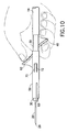
- FIG. 10 is a side plan view of the blood collection set shown in FIG. 1 showing the outer shield in a retracted position;
- FIG. 11 is a side plan view of the blood collection set shown in FIG. 1 showing the outer shield in an extended position.
- FIG. 1 illustrates a blood collection set 10 in accordance with the present invention and the related features.
- the present invention is generally described in terms of a blood collection set, and encompasses such a blood collection set as well as a shieldable needle assembly for use in such a blood collection set.
- blood collection set 10 includes a shieldable needle device 12 , a flexible tube 14 extending from needle device 12 and a fixture 16 mounted to flexible tube 14 .
- Shieldable needle device 12 of blood collection set 10 is shown in detail in FIGS. 2-9, and includes a needle cannula 20 , a hub 30 and an outer shield 50 .
- Fixture 16 is connectable to a receptacle (not shown) for use in blood collection procedures, as is known in the art.
- Needle cannula 20 includes a proximal end 22 and an opposing distal end 24 , with lumen 26 extending through needle cannula 20 from proximal end 22 to distal end 24 .
- Distal end 24 of needle cannula 20 is beveled to define a sharp puncture tip 28 , such as an intravenous puncture tip. Puncture tip 28 is provided for insertion into a patient's blood vessel, such as a vein, and is therefore designed to provide ease of insertion and minimal discomfort during venipuncture.
- a removable protective cover (not shown) may be positioned over distal end 24 of needle cannula 20 for protection from puncture tip 28 prior to use of blood collection set 10 .
- Needle assembly 12 further includes hub 30 .
- Hub 30 is a unitary structure, desirably molded from a thermoplastic material.
- Hub 30 is a generally elongated tubular body having a proximal end 32 , a distal end 34 , an outer surface 36 and an internal passageway 38 extending therethrough from proximal end 32 to distal end 34 .
- Needle cannula 20 is positioned within and is supported by internal passageway 38 of hub 30 , with distal end 24 of needle cannula 20 extending from distal end 34 of hub 30 .
- needle cannula 20 and hub 30 are separate parts which are fixedly attached and secured through an appropriate medical grade adhesive or the like. As shown in FIG.
- hub 30 may include a restriction 293 adjacent distal end 34 thereof, against which proximal end 22 of needle cannula 20 may abut.
- needle cannula 20 may extend within the entire length of hub 30 to the proximal end 32 of hub 30 .
- Proximal end 32 of hub 30 is adapted for connection with a flexible tube 14 of blood collection set 10 .
- Hub 30 desirably includes ribs 46 extending circumferentially about outer surface 36 at proximal end 32 of hub 30 , for coupling with flexible tube 14.
- Hub 30 further includes a first tab 40 extending outwardly from outer surface 36 at a location adjacent proximal end 32 of hub 30 , and at a position distal to ribs 46 . More particularly, first tab 40 extends from outer surface 36 of hub 30 at a position in front of the connection between hub 30 and flexible tube 14 . In this manner, flexible tab 40 is accessible to a user's finger when needle device 12 is assembled with first tube 14 in blood collection set 10 .
- first tab 40 extends from outer surface 36 at a bottom portion of hub 30 adjacent proximal end 32 of hub 30 . Moreover, first tab 40 desirably extends in a direction toward flexible tube 14 . First tab 40 includes a ramped surface 42 having protrusions 44 thereon, for providing frictional engagement with a user's finger.
- Needle assembly 12 further includes hollow outer shield 50 .
- Outer shield 50 includes a housing 52 .
- Housing 52 is a unitary structure, desirably molded from a thermoplastic material, including a proximal end 54 , a distal end 56 and an internal passageway 58 extending between proximal end 54 and distal end 56 .
- the inner wall of housing 52 defines an internal surface 60 therethrough.
- Outer shield 50 further includes a second tab 62 extending outwardly from a top portion of housing 52 near proximal end 54 of outer shield 50 .
- Second tab 62 extends outwardly from outer shield 50 in a direction toward distal end 56 of outer shield 50 .
- Second tab 62 includes a ramped surface 64 having protrusions 66 thereon for providing frictional engagement with a user's thumb.
- Outer shield 50 co-axially surrounds distal end 34 of hub 30 .
- proximal end 32 of hub 30 extends beyond proximal end 54 of outer shield 50 such that first tab 40 of hub 30 extends beyond proximal end 54 of outer shield 50 .
- internal surface 60 of outer shield 50 is in cooperating engagement with outer surface 36 of hub 30 .
- Outer shield 50 is movable between a retracted position in which first tab 40 is exposed from proximal end 54 of outer shield 50 and puncture tip 28 is exposed from distal end 56 of outer shield 50 , and an extended position in which puncture tip 28 and distal end 24 of needle cannula 20 are covered by outer shield 50 .
- First tab 40 and second tab 62 are configured such that opposing forces applied against first tab 40 and second tab 62 cause outer shield 50 to move toward distal end 24 of needle cannula 20 in a direction of arrow 100 from the retracted position to the extended position.
- Protrusions 44 and 66 on first tab 40 and second tab 62 respectively, provide frictional engagement with the user's finger and thumb, respectively, to facilitate moving outer shield 50 from the retracted position to the extended position.
- Outer shield 50 may further include a pair of stabilizers in the form of wings 68 extending laterally from outer shield 50 at opposing sides thereof, providing blood collection set 10 as a butterfly-type wing assembly.
- Wings 68 assist in positioning and placing needle device 12 and blood collection set 10 during a blood collection procedure and are adapted to lie flat against the surface of a patient's skin during the blood collection procedure.
- wings 68 may be constructed of a flexible material such that at least one, and desirably both, of wings 68 can be bent toward each other and brought together between the fingers of the user to assist in positioning and placing needle device 12 during venipuncture.
- Housing 52 of outer shield 50 may also include a cutaway portion 70 extending through at least one side of housing 52 , and desirably, extending through both sides of housing 52 at opposing lateral sides. Cutaway portion 70 defines a flexible finger 72 , which is adapted for radial outward flexing during movement of outer shield 50 from the retracted position to the extended position, thereby permitting sliding engagement of outer shield 50 with respect to hub 30 about the cooperating surfaces thereof.
- outer surface 36 of hub 30 and internal surface 60 of outer shield 50 include a plurality of corresponding grooves and ramped surfaces for providing cooperating axial movement therebetween in a predetermined manner.
- outer surface 36 of hub 30 includes a front shoulder 246 of relatively large diameter.
- the front shoulder 246 is defined by a front face 247 and a rear abutment face 248 .
- a first groove 238 is defined on one side by the abutment face 248 and on its other side by the termination (rear abutment face) 250 of a ramped surface 252 .
- the ramped surface 252 starts with a diameter smaller than that of the front shoulder 246 and ramps downward away from the first groove 238 .
- Ramp 252 terminates in a long valley 242 defined by outer surface 36 of hub 30 .
- the valley 242 has a relatively constant diameter which is preferably substantially equal to the diameter of the first groove 238 .
- the valley ends in a ramp 254 which increases in diameter as it extends away from distal end 34 and towards proximal end 32 of hub 30 .
- Ramp 254 is followed by ramp 256 which ramps down to a second groove 236 .
- Second groove 236 is preferably of a diameter slightly larger than the diameter of valley 242 , and terminates in a rear abutment surface 259 .
- Surface 259 is also the terminating surface of a rear ramp 262 , which ends at portion 264 extending along proximal end 32 of hub 30 .
- First tab 40 and ribs 46 extend from hub 30 at portion 264 extending along proximal end 32 of hub 30.
- hub 30 may be non-cylindrical such that it will not rotate inside of outer shield 50 .
- front shoulder 246 , and ramps 252 , 254 , 256 , and 262 do not appear on the bottom of outer surface 36 of hub 30 .
- the term “diameter” is used in a broad sense to indicate relative cross-sectional dimensions.
- Housing 52 of outer shield 50 may be nearly semicircular in cross-sectional shape, with a flat bottom surface 295 .
- Flat bottom surface 295 is preferably a tapered surface (as seen in FIG. 8), with the thickness of the bottom increasing according to a two and one half degree slope as it extends away from distal end 56 of outer shield 50 .
- needle cannula 20 assumes a downward angle preferably of about two and one half degrees, and is more easily and comfortably inserted into the vein of the patient.
- Internal surface 60 of housing 52 is of a diameter slightly larger than the outer diameter of front shoulder 246 of hub 30 .
- the inner surface of housing 52 is arranged with two ramps 285 and 292 , although, if desired, ramp 285 may be replaced with a non-ramped protrusion.
- ramp 285 provides housing 52 with a decreasing inner diameter as it extends toward proximal end 54 of outer shield 50 .
- Ramp 285 terminates in an abutment face 289 which is followed by a flat surface 287 having an inner diameter approximately equal to the outer diameter of shoulder 246 of hub 30 .
- Flat surface 287 ends with ramp 292 which also has a decreasing inner diameter as it extends toward proximal end 54 of outer shield 50 .
- the inner diameter at the end of ramp 292 is of significantly smaller diameter than that of ramp 285 .
- Internal surface 60 of outer shield 50 terminates in a flat protrusion 234 of significantly smaller diameter than the of the front shoulder 246, with rear surface 299 provided at proximal end 54 of housing 52.
- Blood collection set 10 can be packaged substantially in the condition shown in FIG. 1.
- blood collection set 10 is provided with needle device 12 assembled and including flexible tube 14 extending from needle device 12 and connected to fixture 16.
- needle device 12 assembled and including flexible tube 14 extending from needle device 12 and connected to fixture 16.
- Fixture 16 may be connected to an appropriate receptacle, such as a non-patient needle assembly and a needle holder, for providing fluid communication with lumen 26 through needle cannula 20.
- the user grasps blood collection set 10 at needle device 12 and removes the protective cover (not shown) to expose puncture tip 28 of needle cannula 20 .
- the medical practitioner can then urge puncture tip 28 at distal end 24 of needle cannula 20 into targeted blood vessel of a patient.
- at least one of wings 68 can be bent inwardly toward the other with the user's fingers to facilitate positioning and placing of needle device 12 .
- needle cannula 20 is withdrawn from the patient. After removal of needle cannula 20 from the patient, activation of the safety feature of needle device 12 is accomplished.
- the user grasps needle device 12 in one hand, with the user's thumb engaging first tab 40 and one of the user's forefingers engaging second tab 62 .
- Opposed forces are exerted on first tab 40 and second tab 62 through the user's thumb and forefinger.
- Such opposing force causes outer shield 50 to move in the direction of arrow 100 from the retracted position to the extended position.
- puncture tip 28 of needle cannula 20 is safely shielded by outer shield 50 in the extended position as shown in FIG. 11. Blood collection set 10 may then be appropriately discarded.
- outer surface 36 of hub 30 and internal surface 60 of outer shield 50 include a plurality of corresponding grooves and surfaces for cooperating engagement as described hereinabove
- an initial force is required to overcome resistance of protrusion 234 sliding over ramp 256 .
- flexible fingers 72 may flex radially outwardly from housing 52 of outer shield 50 , thereby decreasing the resistance and permitting axial movement of outer shield 50 along hub 30 .
- protrusion 234 slides over ramp 256 little force is needed to continue sliding outer shield 50 over valley 242 of hub 30. Additional resistance is encountered when ramp 252 of hub 30 encounters ramp 285 of housing 52 , as well as when ramp 285 encounters front shoulder 246 .
- the design of needle device 12 including the cooperating surface assists in proper movement between the retracted position and the extended position.
- radial flexing of flexible fingers 72, the ramped nature of ramp 285 and the rounding of the edge of shoulder 246 permit ramp 285 to be slid over front shoulder 246 until it snaps over front shoulder 246 with abutment face 289 of outer shield 50 in contact with abutment surface 247 of front shoulder 246 of hub 30 .
- protrusion 234 sits in first groove 238 with rear surface 299 of outer shield 50 abutting abutment surface 250 of hub 30 , and front shoulder 246 contacts surface 287 .
- puncture tip 28 of needle cannula 20 is shielded entirely and securely by outer shield 50 .
- Two locking interactions are established (abutment face 289 against shoulder 246 , and rear surface 299 against surface 250 ) as seen in FIG. 6 to prevent return movement of outer shield 50 to the retracted position and reexposing of needle cannula 20 , while the relative sizes of protrusion 234 and shoulder 246 prevent any possibility of outer shield 50 being pulled forward off of hub 30 .
- needle assembly of the present invention has been described in terms of one embodiment for use in connection with a blood collection system, it is further contemplated that the needle assembly could be used with other medical procedures, such as in conjunction with a conventional intravenous infusion set, which are well-known in the art for use with needle assemblies.
Landscapes
- Health & Medical Sciences (AREA)
- Engineering & Computer Science (AREA)
- Life Sciences & Earth Sciences (AREA)
- Anesthesiology (AREA)
- General Health & Medical Sciences (AREA)
- Biomedical Technology (AREA)
- Heart & Thoracic Surgery (AREA)
- Hematology (AREA)
- Veterinary Medicine (AREA)
- Animal Behavior & Ethology (AREA)
- Public Health (AREA)
- Vascular Medicine (AREA)
- Environmental & Geological Engineering (AREA)
- Biophysics (AREA)
- Pulmonology (AREA)
- Measurement Of The Respiration, Hearing Ability, Form, And Blood Characteristics Of Living Organisms (AREA)
- Infusion, Injection, And Reservoir Apparatuses (AREA)
- Media Introduction/Drainage Providing Device (AREA)
Claims (10)
- Aiguille, comprenant :une canule d'aiguille (20) possédant une extrémité proximale (22) et une extrémité distale (24) avec une pointe de ponction (28) ;un moyeu (30) comprenant un corps tubulaire allongé possédant une surface externe (36), une extrémité proximale (32), une extrémité distale (34) et un passage (38) s'étendant à travers ledit moyeu (30), ladite extrémité distale (34) dudit moyeu (30) supportant ladite canule d'aiguille (20), ledit moyeu (30) comprenant en outre une première patte (40) s'étendant vers l'extérieur à partir de ladite extrémité proximale (32) dudit corps tubulaire ; etun manchon de protection externe creux (50) comprenant un logement (52) possédant une extrémité proximale (54), une extrémité distale (56), un passage (58) s'étendant à partir de ladite extrémité proximale (54) vers ladite extrémité distale (56), et une seconde patte (62) s'étendant vers l'extérieur à partir dudit logement (52), ledit manchon de protection (50) externe entourant de manière coaxiale ladite extrémité distale (34) dudit corps tubulaire dudit moyeu (30) et incluant une surface interne (60) en enclenchement de coopération avec ladite surface externe (36) dudit corps tubulaire dudit moyeu (30), ledit manchon de protection externe (50) pouvant être déplacé entre une position rentrée dans laquelle ladite première patte (40) s'étendant à partir dudit corps tubulaire est exposée à partir de ladite extrémité proximale dudit manchon de protection externe (50) et ladite pointe de ponction (28) de ladite canule d'aiguille (20) est exposée à partir de ladite extrémité distale (56) dudit manchon de protection externe (50), et une position sortie dans laquelle ledit manchon de protection externe (50) couvre ladite pointe de ponction (28) de ladite canule d'aiguille ; un tube flexible (14) étant relié à ce moyeu (30)caractérisée en ce que
ladite première patte (40) s'étend dudit moyeu (30) en direction dudit tube flexible (14) par rapport à un axe dudit corps tubulaire, ladite seconde patte (62) s'étend à partir dudit manchon de protection externe (50) dans une direction essentiellement opposée à la direction de ladite première patte (40) et où ladite première patte (40) et ladite seconde patte (62) sont configurées de telle sorte que des forces opposées appliquées contre ladite première patte (40) et ladite seconde patte (62) génèrent le déplacement dudit manchon de protection externe (50) vers ladite extrémité distale (24) de ladite canule d'aiguille (20) à partir de ladite position rentrée jusqu'à ladite position sortie. - Aiguille selon la revendication 1, dans laquelle ladite première patte (40) s'étend à partir d'une partie inférieure dudit moyeu (30) et ladite seconde patte (62) s'étend à partir d'une partie supérieure dudit logement (52) dudit manchon de protection externe (50).
- Aiguille selon la revendication 1 ou 2, dans laquelle ledit manchon de protection externe (50) inclut une paire d'éléments d'ailes (68) s'étendant de manière latérale à partir des côtés opposés dudit logement (52).
- Aiguille selon l'une quelconque des revendications 1 à 3, dans laquelle ladite surface externe (36) dudit moyeu (30) inclut une série de rainures et de rampes et ladite surface interne (60) dudit manchon de protection externe (50) coopère avec ladite surface externe (36) dudit moyeu (30), lesdites rainures et rampes fournissant un enclenchement par frictions entre ledit manchon de protection externe (50) et ledit moyeu (30).
- Aiguille selon l'une quelconque des revendications 1 à 4, dans laquelle ledit logement (52) dudit manchon de protection externe (50) inclut au moins une partie coupée (70) s'étendant à travers ledit logement (52) et définissant un doigt flexible (72), ledit au moins un doigt flexible (72) étant adapté pour fléchir vers l'extérieur pendant le mouvement dudit manchon de protection externe (50) à partir de ladite position rentrée jusqu'à ladite position sortie.
- Aiguille selon l'une quelconque des revendications 1 à 5, dans laquelle ladite extrémité proximale (32) dudit moyeu (30) est adaptée pour un raccordement à un tube flexible (14) d'un ensemble de prélèvement sanguin (10).
- Aiguille selon l'une quelconque des revendications 1 à 6, dans laquelle ladite première (40) et ladite (62) pattes incluent des saillies (44) (46) pour un enclenchement par frictions avec le doigt ou le pouce d'un utilisateur, respectivement.
- Ensemble de prélèvement sanguin avec gaine (10) comprenant une aiguille (12) tel que déterminée dans l'une quelconque des revendications 1 à 7, un tube flexible (14) ayant les première et seconde extrémités opposées, la seconde extrémité dudit tube flexible (14) étant relié à ladite extrémité proximale (32) dudit moyeu (30), ledit ensemble de prélèvement sanguin avec gaine (10) comprenant en outre un dispositif de serrage (16) relié à ladite première extrémité dudit tube flexible, ledit dispositif de serrage (16) étant configuré pour relier l'ensemble de prélèvement de sang (10) à un réceptacle.
- Ensemble de prélèvement sanguin selon la revendication 8, dans lequel ladite première patte (40) inclut une surface à rampe (42) s'étendant vers l'extérieur à partir dudit corps tubulaire dudit moyeu (30) au niveau de ladite extrémité proximale (32) dudit moyeu (30) en direction dudit tube flexible (14).
- Ensemble de prélèvement sanguin selon la revendication 8 ou 9, dans lequel ladite seconde patte (62) inclut une surface à rampe (64) s'étendant vers l'extérieur dudit logement (52) dudit manchon de protection externe (50) au niveau de ladite extrémité proximale (54) dudit manchon de protection externe (50) en direction de ladite extrémité distale (56) dudit manchon de protection externe (50).
Applications Claiming Priority (2)
| Application Number | Priority Date | Filing Date | Title |
|---|---|---|---|
| US10/100,307 US6623461B1 (en) | 2002-03-15 | 2002-03-15 | Forward shielding safety device |
| US100307 | 2002-03-15 |
Publications (3)
| Publication Number | Publication Date |
|---|---|
| EP1352668A2 EP1352668A2 (fr) | 2003-10-15 |
| EP1352668A3 EP1352668A3 (fr) | 2003-10-22 |
| EP1352668B1 true EP1352668B1 (fr) | 2007-01-17 |
Family
ID=28039775
Family Applications (1)
| Application Number | Title | Priority Date | Filing Date |
|---|---|---|---|
| EP02025276A Expired - Lifetime EP1352668B1 (fr) | 2002-03-15 | 2002-11-12 | Manchon de protection pour aiguille |
Country Status (7)
| Country | Link |
|---|---|
| US (2) | US6623461B1 (fr) |
| EP (1) | EP1352668B1 (fr) |
| JP (1) | JP4564710B2 (fr) |
| AU (1) | AU2003200121B2 (fr) |
| CA (1) | CA2407441A1 (fr) |
| DE (1) | DE60217643T2 (fr) |
| ES (1) | ES2278859T3 (fr) |
Cited By (1)
| Publication number | Priority date | Publication date | Assignee | Title |
|---|---|---|---|---|
| US10518045B2 (en) | 2014-12-04 | 2019-12-31 | Owen Mumford Limited | Needle assemblies |
Families Citing this family (47)
| Publication number | Priority date | Publication date | Assignee | Title |
|---|---|---|---|---|
| US20030220587A1 (en) * | 2002-05-23 | 2003-11-27 | Becton Dickinson And Company | Medical device |
| US11083841B2 (en) | 2002-08-09 | 2021-08-10 | Fenwal, Inc. | Needle protector, needle assembly and fluid processing set including the same |
| US7704229B2 (en) * | 2005-02-03 | 2010-04-27 | Medtronic Minimed, Inc. | Insertion device |
| DE602006005674D1 (de) | 2005-07-06 | 2009-04-23 | Vascular Pathways Inc | Gerät zur intravenösen kathetereinführung und verwendungsverfahren |
| CA2622887C (fr) | 2005-09-22 | 2014-11-18 | Tyco Healthcare Group Lp | Aiguille de surete a mecanisme de verrouillage |
| CN101330937B (zh) * | 2005-09-22 | 2012-07-18 | 泰科保健集团有限合伙公司 | 带有刚性翼结构的手动退回安全针 |
| US8118786B2 (en) * | 2006-03-29 | 2012-02-21 | Kawasumi Laboratories, Inc. | Guarded medical winged needle assembly |
| US8888713B2 (en) | 2007-03-07 | 2014-11-18 | Becton, Dickinson And Company | Safety blood collection assembly with indicator |
| CA2679968C (fr) | 2007-03-07 | 2013-07-02 | Becton, Dickinson And Company | Assemblage securise de collecte de sang avec indicateur |
| ATE548972T1 (de) | 2007-05-07 | 2012-03-15 | Vascular Pathways Inc | Intravenöse kathetereinführungs- und blutprobenvorrichtung |
| US8603009B2 (en) | 2008-03-07 | 2013-12-10 | Becton, Dickinson And Company | Flashback blood collection needle |
| US8795198B2 (en) * | 2008-03-07 | 2014-08-05 | Becton, Dickinson And Company | Flashback blood collection needle |
| US8323249B2 (en) | 2009-08-14 | 2012-12-04 | The Regents Of The University Of Michigan | Integrated vascular delivery system |
| US8216186B2 (en) * | 2010-03-10 | 2012-07-10 | Becton, Dickinson And Company | Catheter device with hooding feature |
| US8932258B2 (en) | 2010-05-14 | 2015-01-13 | C. R. Bard, Inc. | Catheter placement device and method |
| US10384039B2 (en) | 2010-05-14 | 2019-08-20 | C. R. Bard, Inc. | Catheter insertion device including top-mounted advancement components |
| US9950139B2 (en) | 2010-05-14 | 2018-04-24 | C. R. Bard, Inc. | Catheter placement device including guidewire and catheter control elements |
| US9872971B2 (en) | 2010-05-14 | 2018-01-23 | C. R. Bard, Inc. | Guidewire extension system for a catheter placement device |
| US11925779B2 (en) | 2010-05-14 | 2024-03-12 | C. R. Bard, Inc. | Catheter insertion device including top-mounted advancement components |
| US8814833B2 (en) | 2010-05-19 | 2014-08-26 | Tangent Medical Technologies Llc | Safety needle system operable with a medical device |
| WO2011146769A2 (fr) | 2010-05-19 | 2011-11-24 | Tangent Medical Technologies Llc | Système intégré d'administration vasculaire |
| WO2012023938A1 (fr) | 2010-08-19 | 2012-02-23 | West Pharmaceutical Services, Inc. | Gaine d'aiguille rigide |
| CN103189094B (zh) * | 2010-09-07 | 2016-08-10 | 保利医疗用品有限公司 | 针保护器组件 |
| BRDI7102911S (pt) * | 2010-12-14 | 2014-06-10 | Poly Medicure Ltd | Configuração aplicada em conjunto de segurança para coleta de sangue |
| US8690833B2 (en) | 2011-01-31 | 2014-04-08 | Vascular Pathways, Inc. | Intravenous catheter and insertion device with reduced blood spatter |
| EP2678065B1 (fr) | 2011-02-25 | 2019-09-11 | C.R. Bard Inc. | Dispositif d'introduction de composant médical comprenant une aiguille rétractable |
| USD903101S1 (en) | 2011-05-13 | 2020-11-24 | C. R. Bard, Inc. | Catheter |
| JP5790972B2 (ja) | 2011-06-07 | 2015-10-07 | 株式会社ジェイ・エム・エス | 留置針装置 |
| JP5854271B2 (ja) * | 2012-02-17 | 2016-02-09 | 株式会社ジェイ・エム・エス | 留置針装置 |
| WO2014120741A1 (fr) | 2013-01-30 | 2014-08-07 | Vascular Pathways, Inc. | Systèmes et procédés pour la ponction veineuse et le placement de cathéter |
| US10350366B2 (en) | 2013-02-01 | 2019-07-16 | Nxstage Medical, Inc. | Safe cannulation devices, methods, and systems |
| SE1350137A1 (sv) * | 2013-02-05 | 2014-08-06 | Vigmed Ab | Nålanordning |
| JP6461174B2 (ja) | 2014-02-04 | 2019-01-30 | アイシーユー・メディカル・インコーポレーテッド | 自己プライミングシステムおよび自己プライミング方法 |
| BR112016010016B1 (pt) * | 2014-04-11 | 2022-05-03 | Shanghai Jinta Medical Co.Ltd | Agulha de coleta de sangue de segurança |
| US10232146B2 (en) | 2014-09-05 | 2019-03-19 | C. R. Bard, Inc. | Catheter insertion device including retractable needle |
| BR112016021855B1 (pt) * | 2014-10-24 | 2022-06-14 | Gemtier Medical (Shanghai) Inc | Agulha de punção de transfusão de veia segura descartável |
| USD903100S1 (en) | 2015-05-01 | 2020-11-24 | C. R. Bard, Inc. | Catheter placement device |
| SG10202006540RA (en) | 2015-05-15 | 2020-08-28 | Bard Inc C R | Catheter placement device including an extensible needle safety component |
| JP6664270B2 (ja) * | 2016-04-26 | 2020-03-13 | 株式会社トップ | プロテクタ付き医療用針 |
| CN109715093B (zh) | 2016-09-12 | 2020-11-06 | C·R·巴德股份有限公司 | 导管插入装置的血液控制 |
| AU2017401073B2 (en) | 2017-03-01 | 2022-06-02 | C. R. Bard, Inc. | Catheter insertion device |
| US11389626B2 (en) | 2018-03-07 | 2022-07-19 | Bard Access Systems, Inc. | Guidewire advancement and blood flashback systems for a medical device insertion system |
| USD921884S1 (en) | 2018-07-27 | 2021-06-08 | Bard Access Systems, Inc. | Catheter insertion device |
| CN213312819U (zh) | 2019-08-19 | 2021-06-01 | 贝克顿·迪金森公司 | 中线导管放置装置 |
| EP4025288A1 (fr) | 2019-09-20 | 2022-07-13 | Bard Peripheral Vascular, Inc. | Dispositif de placement de cathéter intraveineux |
| US11896787B2 (en) * | 2019-09-30 | 2024-02-13 | Becton, Dickinson And Company | Anti-rotation catheter devices, systems, and methods |
| US12447283B2 (en) | 2020-03-10 | 2025-10-21 | Vigmed Ab | Needle shielding device |
Family Cites Families (27)
| Publication number | Priority date | Publication date | Assignee | Title |
|---|---|---|---|---|
| US3595230A (en) * | 1968-07-25 | 1971-07-27 | Abbott Lab | Intravenous catheter placement unit with tubular guide sheath |
| US4326519A (en) * | 1980-02-21 | 1982-04-27 | Abbott Laboratories | Venipuncture device |
| USRE36447E (en) | 1985-07-29 | 1999-12-14 | Btg International Limited | Safety device for hypodermic needle or the like |
| US4826490A (en) | 1985-07-29 | 1989-05-02 | National Research Development Corporation | Safety device for hypodermic needle or the like |
| US4737144A (en) * | 1987-03-09 | 1988-04-12 | Choksi Pradip V | Syringe with selectively exposed and enveloped needle |
| US4950252A (en) * | 1987-11-02 | 1990-08-21 | Luther Medical Products, Inc. | Single hand actuated locking safety catheter and method of use |
| US5085639A (en) | 1988-03-01 | 1992-02-04 | Ryan Medical, Inc. | Safety winged needle medical devices |
| US5088982A (en) | 1988-03-01 | 1992-02-18 | Ryan Medical, Inc. | Safety winged needle medical devices |
| US5154699A (en) | 1988-03-01 | 1992-10-13 | Ryan Medical, Inc. | Safety winged needle device for use with fistulas |
| JP2673682B2 (ja) | 1988-03-03 | 1997-11-05 | テルモ株式会社 | 翼付医療用針 |
| JPH0246861A (ja) * | 1988-08-08 | 1990-02-16 | Haruo Yoshida | 感染防止用注射装置 |
| EP0558162B1 (fr) | 1988-09-30 | 1996-03-06 | David S. Utterberg | Ensemble d'aiguille protégée |
| US5266072A (en) | 1988-09-30 | 1993-11-30 | Utterberg David S | Guarded winged needle assembly |
| US4964854A (en) * | 1989-01-23 | 1990-10-23 | Luther Medical Products, Inc. | Intravascular catheter assembly incorporating needle tip shielding cap |
| NL9002552A (nl) * | 1990-09-05 | 1992-04-01 | Advanced Protective Injection | Infusie- of transfusienaaldsamenstel. |
| US5120320A (en) | 1991-02-13 | 1992-06-09 | Becton, Dickinson And Company | I.V. infusion or blood collection assembly with automatic safety feature |
| US5290264A (en) | 1991-09-03 | 1994-03-01 | Utterberg David S | Grippable guard for needle assembly |
| US5192275A (en) | 1991-09-18 | 1993-03-09 | Becton, Dickinson And Company | IV infusion or blood collection guard assembly |
| US5312359A (en) * | 1991-12-03 | 1994-05-17 | Wallace Henry G | Intravenous cannula insertion assembly with protective shield |
| AUPM520694A0 (en) | 1994-04-20 | 1994-05-12 | Noble House Group Pty Ltd | Protective sheath |
| US5562637A (en) | 1994-07-15 | 1996-10-08 | Utterberg; David S. | Needle protector sheath |
| US5562636A (en) | 1994-07-15 | 1996-10-08 | Utterberg; David S. | Needle protector sheath |
| US5498241A (en) * | 1994-12-08 | 1996-03-12 | Abbott Laboratories | Winged needle assembly with protective member |
| CA2169220A1 (fr) * | 1995-03-16 | 1996-09-17 | Greg L. Brimhall | Catheter avec embout d'aiguille retractable dans le catheter par une simple manipulation |
| US5738665A (en) * | 1996-09-26 | 1998-04-14 | Becton, Dickinson And Company | Shield and actuator for needles |
| AU8144198A (en) * | 1997-06-16 | 1999-01-04 | Becton Dickinson & Company | Shield for catheter introducer needles |
| US5997507A (en) * | 1998-08-07 | 1999-12-07 | Dysarz; Edward D. | Biased spring hard needle retractable IV catheter |
-
2002
- 2002-03-15 US US10/100,307 patent/US6623461B1/en not_active Expired - Lifetime
- 2002-10-10 CA CA002407441A patent/CA2407441A1/fr not_active Abandoned
- 2002-11-12 ES ES02025276T patent/ES2278859T3/es not_active Expired - Lifetime
- 2002-11-12 DE DE60217643T patent/DE60217643T2/de not_active Expired - Lifetime
- 2002-11-12 EP EP02025276A patent/EP1352668B1/fr not_active Expired - Lifetime
- 2002-11-26 JP JP2002342025A patent/JP4564710B2/ja not_active Expired - Lifetime
-
2003
- 2003-01-13 AU AU2003200121A patent/AU2003200121B2/en not_active Expired
- 2003-07-28 US US10/628,223 patent/US7060055B2/en not_active Expired - Lifetime
Cited By (1)
| Publication number | Priority date | Publication date | Assignee | Title |
|---|---|---|---|---|
| US10518045B2 (en) | 2014-12-04 | 2019-12-31 | Owen Mumford Limited | Needle assemblies |
Also Published As
| Publication number | Publication date |
|---|---|
| DE60217643D1 (de) | 2007-03-08 |
| JP4564710B2 (ja) | 2010-10-20 |
| EP1352668A3 (fr) | 2003-10-22 |
| US6623461B1 (en) | 2003-09-23 |
| AU2003200121A1 (en) | 2003-10-02 |
| CA2407441A1 (fr) | 2003-09-15 |
| AU2003200121B2 (en) | 2009-07-30 |
| US20030176842A1 (en) | 2003-09-18 |
| EP1352668A2 (fr) | 2003-10-15 |
| ES2278859T3 (es) | 2007-08-16 |
| US7060055B2 (en) | 2006-06-13 |
| JP2003265610A (ja) | 2003-09-24 |
| US20040024370A1 (en) | 2004-02-05 |
| DE60217643T2 (de) | 2007-10-11 |
Similar Documents
| Publication | Publication Date | Title |
|---|---|---|
| EP1352668B1 (fr) | Manchon de protection pour aiguille | |
| EP1543859B1 (fr) | Appareil de sécurité activé passivement pour aiguille du kit de collecte de sang | |
| US7201740B2 (en) | Forward-shielding blood collection set | |
| US5007901A (en) | Intravenous catheter insertion device | |
| EP2266462B1 (fr) | Dispositif d'aiguille à protection équipé d'un manchon de protection actionné par un ressort à lame | |
| US9402964B2 (en) | Passively shielding needle device | |
| EP1449560B1 (fr) | Dispositif médical avec gaine comportant une aiguille rétractable | |
| EP1293162A2 (fr) | Aiguille pour prise de sang avec bouclier de protection | |
| AU648224B2 (en) | Safety winged needle medical devices | |
| EP1537890A1 (fr) | Aiguille médicale avec protecteur automatique | |
| US20030036731A1 (en) | Blood collection assembly | |
| US20030220587A1 (en) | Medical device | |
| EP3246057B1 (fr) | Dispositif de collecte de sang à sûreté activée par un double élément d'entraînement passif | |
| WO1988007387A1 (fr) | Aiguille de securite retractable | |
| CA2520353C (fr) | Ensemble d'aiguille et de catheter de securite |
Legal Events
| Date | Code | Title | Description |
|---|---|---|---|
| PUAI | Public reference made under article 153(3) epc to a published international application that has entered the european phase |
Free format text: ORIGINAL CODE: 0009012 |
|
| PUAL | Search report despatched |
Free format text: ORIGINAL CODE: 0009013 |
|
| AK | Designated contracting states |
Kind code of ref document: A2 Designated state(s): AT BE BG CH CY CZ DE DK EE ES FI FR GB GR IE IT LI LU MC NL PT SE SK TR |
|
| AX | Request for extension of the european patent |
Extension state: AL LT LV MK RO SI |
|
| AK | Designated contracting states |
Kind code of ref document: A3 Designated state(s): AT BE BG CH CY CZ DE DK EE ES FI FR GB GR IE IT LI LU MC NL PT SE SK TR |
|
| AX | Request for extension of the european patent |
Extension state: AL LT LV MK RO SI |
|
| 17P | Request for examination filed |
Effective date: 20040401 |
|
| AKX | Designation fees paid |
Designated state(s): DE ES FR GB IT |
|
| GRAP | Despatch of communication of intention to grant a patent |
Free format text: ORIGINAL CODE: EPIDOSNIGR1 |
|
| GRAS | Grant fee paid |
Free format text: ORIGINAL CODE: EPIDOSNIGR3 |
|
| GRAA | (expected) grant |
Free format text: ORIGINAL CODE: 0009210 |
|
| AK | Designated contracting states |
Kind code of ref document: B1 Designated state(s): DE ES FR GB IT |
|
| REG | Reference to a national code |
Ref country code: GB Ref legal event code: FG4D |
|
| REF | Corresponds to: |
Ref document number: 60217643 Country of ref document: DE Date of ref document: 20070308 Kind code of ref document: P |
|
| ET | Fr: translation filed | ||
| REG | Reference to a national code |
Ref country code: ES Ref legal event code: FG2A Ref document number: 2278859 Country of ref document: ES Kind code of ref document: T3 |
|
| PLBE | No opposition filed within time limit |
Free format text: ORIGINAL CODE: 0009261 |
|
| STAA | Information on the status of an ep patent application or granted ep patent |
Free format text: STATUS: NO OPPOSITION FILED WITHIN TIME LIMIT |
|
| 26N | No opposition filed |
Effective date: 20071018 |
|
| REG | Reference to a national code |
Ref country code: FR Ref legal event code: ST Effective date: 20080930 |
|
| REG | Reference to a national code |
Ref country code: ES Ref legal event code: FD2A Effective date: 20071113 |
|
| PG25 | Lapsed in a contracting state [announced via postgrant information from national office to epo] |
Ref country code: FR Free format text: LAPSE BECAUSE OF NON-PAYMENT OF DUE FEES Effective date: 20071130 Ref country code: ES Free format text: LAPSE BECAUSE OF NON-PAYMENT OF DUE FEES Effective date: 20071113 |
|
| PGFP | Annual fee paid to national office [announced via postgrant information from national office to epo] |
Ref country code: GB Payment date: 20211020 Year of fee payment: 20 Ref country code: DE Payment date: 20211020 Year of fee payment: 20 |
|
| PGFP | Annual fee paid to national office [announced via postgrant information from national office to epo] |
Ref country code: IT Payment date: 20211025 Year of fee payment: 20 |
|
| REG | Reference to a national code |
Ref country code: DE Ref legal event code: R071 Ref document number: 60217643 Country of ref document: DE |
|
| REG | Reference to a national code |
Ref country code: GB Ref legal event code: PE20 Expiry date: 20221111 |
|
| PG25 | Lapsed in a contracting state [announced via postgrant information from national office to epo] |
Ref country code: GB Free format text: LAPSE BECAUSE OF EXPIRATION OF PROTECTION Effective date: 20221111 |