EP1353438A1 - Feedforward amplifier, communication apparatus, feedforward amplifying method, program and medium - Google Patents
Feedforward amplifier, communication apparatus, feedforward amplifying method, program and medium Download PDFInfo
- Publication number
- EP1353438A1 EP1353438A1 EP01271109A EP01271109A EP1353438A1 EP 1353438 A1 EP1353438 A1 EP 1353438A1 EP 01271109 A EP01271109 A EP 01271109A EP 01271109 A EP01271109 A EP 01271109A EP 1353438 A1 EP1353438 A1 EP 1353438A1
- Authority
- EP
- European Patent Office
- Prior art keywords
- distortion
- output signal
- power divider
- signal
- frequency range
- Prior art date
- Legal status (The legal status is an assumption and is not a legal conclusion. Google has not performed a legal analysis and makes no representation as to the accuracy of the status listed.)
- Granted
Links
Images


Classifications
-
- H—ELECTRICITY
- H03—ELECTRONIC CIRCUITRY
- H03F—AMPLIFIERS
- H03F1/00—Details of amplifiers with only discharge tubes, only semiconductor devices or only unspecified devices as amplifying elements
- H03F1/32—Modifications of amplifiers to reduce non-linear distortion
- H03F1/3223—Modifications of amplifiers to reduce non-linear distortion using feed-forward
- H03F1/3229—Modifications of amplifiers to reduce non-linear distortion using feed-forward using a loop for error extraction and another loop for error subtraction
Definitions
- the present invention relates to a feedforward amplifier, communication apparatus, feedforward amplification method, program and medium used for a base station apparatus of mobile communication equipment, etc.
- a high-output linear power amplifier compensated for distortion according to a feedforward system is used for a base station apparatus of mobile communication equipment.
- reference numeral 1 denotes an input terminal; 2, an output terminal; 3 and 9, power dividers; 4 and 10, power combiners; 5 and 12, vector adjustors; 7, a main amplifier; 8 and 11, delay circuits; 13, an auxiliary amplifier.
- reference characters a to k and m marked on the power dividers 3 and 9, power combiners 4 and 10 denote their respective ports.
- an input signal including a plurality of carrier frequency components input from the input terminal 1 is divided into two portions by the power divider 3 and output from port b and port c, respectively.
- the signal output from the port b is passed through the vector adjustor 5 and amplified by the main amplifier 7, passed through the power divider 9 and delay circuit 11 and input to port j of the power combiner 4.
- a signal including not only the carrier frequency components but also distortion components originated by intermodulation are input.
- Furthermore part of the output signal of the main amplifier 7 is extracted from port f of the power divider 9 and input to port h of the power combiner 10.
- the signal output from the port c is passed through the delay circuit 8 and input to port g of the power combiner 10.
- the signal output from the port i is passed through the vector adjustor 12, amplified by the auxiliary amplifier 13 and input to the port k of the power combiner 4.
- a signal including only the carrier frequency components with the distortion components canceled out is output from the port m of the power combiner 4 to the output terminal 2.
- pre-distortion compensation system a pre-distortion compensation system
- reference numeral 61 denotes a power divider; 62, a power divider; 63, a delay circuit; 69, a vector adjustor; 72, a distortion generation circuit.
- the power divider 61, power combiner 62, delay circuit 63, vector adjustor 69 and distortion generation circuit 72 constitute a pre-distortion circuit 6.
- reference character n marked on the power combiner 62 denotes a port.
- the pre-distortion system is a system for suppressing distortion by inputting signals having the same frequency components as those of the distortion components generated at the main amplifier 7 into the main amplifier 7 with an appropriate amplitude/phase relationship.
- the input signal including the plurality of carrier frequency components input from the input terminal (the terminal on the left side in Figure 13) is divided into two portions by the power divider 61.
- One portion of the two divided output signals is input to the power combiner 62 through the delay circuit 63.
- the other portion of output signal is input to the distortion generation circuit 72, which outputs a signal with the same frequency component as the distortion component generated at the main amplifier 7.
- the signal output at the distortion generation circuit 72 is input to the power combiner 62 through the vector adjustor 69 and combined with the output signal from the delay circuit 63.
- the vector adjustor 69 is adjusted in such a way as to have an appropriate amplitude/phase relationship with the input signal.
- the signal combined at the power combiner 62 is output from the port n and input to the main amplifier 7.
- a feedforward amplifier using the pre-distortion system together with feedforward system has also performed suppression in such a way that the distortion component on the high frequency side and the distortion component on the low frequency side reach the same level, but especially when the distortion component generated at the main amplifier 7 has an unbalance between the high frequency side and low frequency side of the carrier band, distortion has not been suppressed efficiently so far for the above-described reasons.
- the present invention has been implemented in view of the above-described conventional problems and it is an object of the present invention to provide a feedforward amplifier, communication apparatus, feedforward amplification method, program and medium capable of efficiently suppressing distortion components.
- a first invention of the present invention (corresponding to Claim 1) is a feedforward amplifier comprising:
- a second invention of the present invention is the feedforward amplifier according to claim 1, wherein said predetermined frequency range is the entire distortion signal band on the high frequency side or low frequency side generated at said main amplifier.
- a third invention of the present invention is the feedforward amplifier according to the first invention of the present invention, wherein said pre-distortion compensation circuit is provided between said first power divider and said first vector adjustor.
- a fourth invention of the present invention is the feedforward amplifier according to the first invention of the present invention, comprising:
- a fifth invention of the present invention is the feedforward amplifier according to the first invention of the present invention, comprising:
- a sixth invention of the present invention is the feedforward amplifier according to the fourth invention, wherein said control means stops the operation of said auxiliary amplifier or the function of said pre-distortion compensation circuit based on a predetermined condition.
- a seventh invention of the present invention is the feedforward amplifier according to the sixth invention of the present invention, comprising input signal level detecting means of detecting the signal level of said input signal, wherein stopping the operation of said auxiliary amplifier or the function of said pre-distortion compensation circuit based on said predetermined condition means that said control means stops the operation of said auxiliary amplifier when the signal level of said detected input signal is equal to or lower than a predetermined value.
- An eighth invention of the present invention is the feedforward amplifier according to the sixth invention of the present invention, comprising input signal level detecting means of detecting the signal level of said input signal, wherein stopping the operation of said auxiliary amplifier or the function of said pre-distortion compensation circuit based on said predetermined condition means that said control means stops the function of said pre-distortion compensation circuit when the signal level of said detected input signal is equal to or lower than a predetermined value.
- a ninth invention of the present invention is the feedforward amplifier according to the sixth invention of the present invention, comprising input signal level detecting means of detecting the signal level of said input signal, wherein stopping the operation of said auxiliary amplifier or the function of said pre-distortion compensation circuit based on said predetermined condition means that said control means (1) stops the function of saidpre-distortion compensation circuit when the signal level of said detected input signal is equal to or lower than a first predetermined value and higher than a second predetermined value which is a value lower than said first predetermined value and (2) stops the operation of said auxiliary amplifier when the signal level of said input signal is equal to or lower than said second predetermined value.
- a tenth invention of the present invention is the feedforward amplifier according to the sixth invention of the present invention comprising:
- An eleventh invention of the present invention is the feedforward amplifier according to any of the seventh to the ninth inventions of the present invention, wherein said input signal level detecting means is provided on a signal line including the input signal component.
- a twelfth invention of the present invention (corresponding to Claim 12) is the feedforward amplifier according to any of the first to the tenth inventions of the present invention, wherein said pre-distortion compensation circuit comprising:
- a thirteenth invention of the present invention is the feedforward amplifier according to the twelfth invention of the present invention, wherein said distortion generation circuit comprising:
- a fourteenth invention of the present invention is the feedforward amplifier according to the twelfth invention of the present invention, wherein automatically adjusting said pre-distortion compensation circuit according to the signal level detected by said distortion level detection circuit means adjusting the amplitude and phase of said third vector adjustor.
- a fifteenth invention of the present invention is the feedforward amplifier according to the twelfth invention of the present invention, wherein stopping the function of said pre-distortion compensation circuit means that the output signal from said distortion generation circuit is not input to said second power combiner.
- a sixteenth invention of the present invention is the feedforward amplifier according to the twelfth invention of the present invention, wherein said distortion generation circuit is constructed of only a distortion generation power amplifier for amplifying an input signal.
- a seventeenth invention of the present invention is the feedforward amplifier according to the twelfth invention of the present invention, wherein said third delay circuit is constructed using all or part of said first delay circuit.
- An eighteenth invention of the present invention is the feedforward amplifier according to the thirteenth invention of the present invention, wherein said fourth delay circuit is constructed using all or part of said first delay circuit.
- a nineteenth invention of the present invention is the feedforward amplifier according to the thirteenth invention of the present invention, wherein said distortion generation power amplifier is constructed of a non-linear device.
- a twentieth invention of the present invention is the feedforward amplifier according to the first invention of the present invention, wherein the distortion component generated within said predetermined frequency range is greater than distortion components generated in a frequency range other than said predetermined frequency range.
- a twenty-first invention of the present invention is the feedforward amplifier according to the first invention of the present invention, wherein an adjustment is made so that the distortion component out of said distortion components to be suppressed, which is generated within the predetermined frequency range is greater than distortion components generated in a frequency range other than the predetermined frequency range.
- a twenty-second invention of the present invention is the feedforward amplifier according to the twenty-first invention of the present invention, comprising:
- a twenty-third invention of the present invention is the feedforward amplifier according to the twenty-second invention of the present invention, wherein said pre-distortion compensation circuit and pilot signal oscillator are automatically adjusted (a) when the signal level detected at said low frequency side distortion level detection circuit is greater than the signal level detected at said high frequency side distortion level detection circuit, in such a way that said predetermined frequency range becomes the frequency range corresponding to said low frequency side and (b) when the signal level detected at said high frequency side distortion level detection circuit is greater than the signal level detected at said low frequency side distortion level detection circuit, in such a way that said predetermined frequency range becomes the frequency range corresponding to said high frequency side.
- a twenty-fourth invention of the present invention is a feedforward amplifier comprising:
- a twenty-fifth invention of the present invention (corresponding to Claim 25) is a communication apparatus using the feedforward amplifier according to any of the first to the twenty-fourth inventions of the present invention.
- a twenty-sixth invention of the present invention (corresponding to Claim 26) is a feedforward amplification method comprising:
- a twenty-seventh invention of the present invention is a feedforward amplification method comprising:
- a twenty-eighth invention of the present invention is a program for allowing a computer to execute all or some of the steps of the feedforward amplification method according to the twenty-sixth invention of the present invention, comprising:
- a twenty-ninth invention of the present invention is a computer-processable medium that stores a program for allowing a computer to execute all or some of the steps of the feedforward amplification method according to the twenty-sixth invention of the present invention, comprising:
- a thirtieth invention of the present invention is a program for allowing a computer to execute all or some of the steps of the feedforward amplification method according to the twenty-seventh invention of the present inveniton, comprising:
- a thirty-first invention of the present invention is a computer-processable medium that stores a program for allowing a computer to execute all or some of the steps of the feedforward amplification method according to the twenty-seventh invention of the present invention, comprising:
- a feature of the present invention is that either the distortion component generated on the high frequency side or low frequency side of a carrier band is mainly subjected to distortion suppression according to a feedforward system and the resulting deterioration of the amount of distortion suppression on the opposite side is compensated according to a pre-distortion system.
- Figure 1 is a block diagram of a feedforward amplifier according to Embodiment 1.
- reference numeral 1 denotes an input terminal; 2, an output terminal; 3 and 9, power dividers; 4 and 10, power combiners; 5 and 12, vector adjusters; 6, a pre-distortion circuit (also called “pre-distortion compensation circuit") ; 7, a main amplifier; 8 and 11, delay circuits; 13, an auxiliary amplifier.
- Reference characters a to k, m and n marked on the power dividers 3 and 9, power combiners 4 and 10, and the pre-distortion circuit 6 denote their respective ports.
- the same means as those in the aforementioned conventional case are assigned the same reference numerals.
- the power divider 3 corresponds to the first power divider of the present invention
- the vector adjustor 5 corresponds to the first vector adjustor of the present invention
- the pre-distortion circuit 6 corresponds to the pre-distortion compensation circuit of the present invention
- the main amplifier 7 corresponds to the main amplifier of the present invention
- the power divider 9 corresponds to the second power divider of the present invention
- the delay circuit 8 corresponds to the first delay circuit of the present invention
- the power combiner 10 corresponds to the distortion detection power combiner of the present invention
- the delay circuit 11 corresponds to the second delay circuit of the present invention
- the vector adjustor 12 corresponds to the second vector adjustor of the present invention
- the auxiliary amplifier 13 corresponds to the auxiliary amplifier of the present invention
- the power combiner 4 corresponds to the distortion elimination power combiner of the present invention.
- An input signal including a plurality of carrier frequency components input from the input terminal 1 is input to port a of the power divider 3.
- the signal input to the port a of the power divider 3 is divided into two portions b and output from port b and port c, respectively.
- the signal output from the port b is passed through the vector adjustor 5 and pre-distortion circuit 6, and amplified by the main amplifier 7. At this time, due to non-linearity of the main amplifier 7, a signal including not only the carrier frequency components but also distortion components originated by intermodulation are input, but as will be explained in detail later, the signal is output with part of the distortion suppressed because the pre-distortion circuit 6 is inserted.
- the output signal of the main amplifier 7 is passed through the power divider 9 and delay circuit 11 and input to port j of the power combiner 4. Part of the output signal of the main amplifier 7 is extracted from port f of the power divider 9 and input to port h of the power combiner 10.
- the signal output from the port c is passed through the delay circuit 8 and input to port g of the power combiner 10.
- the vector adjustor 5 and delay circuit 8 so that the carrier frequency components of the signals input to the port g and port h have the same amplitude and opposite phases, a signal including only the distortion components with the carrier frequency components canceled out is output from the port i.
- the signal output from the port i is passed through the vector adjustor 12, amplifiedby the auxiliary amplifier 13 and input to the port k of the power combiner 4.
- a signal including only the carrier frequency components with the distortion components canceled out is output from the port m of the power combiner 4 to the output terminal 2.
- Figure 2(a) illustrates a frequency spectrum of a signal at port a
- Figure 2(b) illustrates a frequency spectrum of a signal at port n
- Figure 2(c) illustrates a frequency spectrum of a signal at port d
- Figure 2(d) illustrates a frequency spectrum of a signal at port i
- Figure 2(e) illustrates a frequency spectrum of a signal at port m.
- Figures 2(a) to Figures 2(e) illustrate carrier levels on a unit basis.
- the vector adjustor 12 is adjusted so that the distortion component on the high frequency side with the high distortion level is mainly suppressed according to a feedforward system, the amount of distortion suppression on the low frequency side deteriorates. Thus, this deterioration will be compensated by suppressing part of the distortion component on the low frequency side through the pre-distortion circuit 6.
- the pre-distortion circuit 6 generates input distortion to suppress part of the distortion component on the low frequency side and obtains a signal output from the port n (see Figure 2(b)).
- This distortion suppression suppresses the level of distortion generated on the lower frequency side than the carrier band of the signal amplified by the main amplifier 7 and input to the port d (see Figure 2(c)), and also suppresses the level of the lower frequency side than the carrier band of the signal output from the port i (see Figure 2(d)) as the signal of only the distortion component.
- the vector adjustor 12 by adjusting the vector adjustor 12 so that the level of distortion generated on the higher frequency side than the carrier band is mainly suppressed, the levels of distortion generated on both the lower frequency side and higher frequency side than the carrier band of the signal are suppressed, causing the signal output from the port m (see Figure 2(e)) to consist substantially of only carrier frequency components.
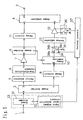
- reference numerals 61, 64, 83, 84 and 88 denote power dividers; 62, 65 and 82 , power combiners; 63 and 66, delay circuits; 67 and 69, vector adjustors; 68, a distortion generation power amplifier; 81, a pilot signal oscillator; 85, abandpass filter; 86, a distortion level detection circuit; 87, a carrier level detection circuit; 89, a pilot level detection circuit; 90, a control circuit.
- the power divider 64, power combiner 65, delay circuit 66, vector adjustor 67 and distortion generation power amplifier 68 constitute a distortion generation circuit 72 .
- the power divider 61, power combiner 62, delay circuit 63, vector adjustor 69 and distortion generation circuit 72 constitute a pre-distortion circuit 6A.
- the pilot signal oscillator 81 corresponds to the pilot signal oscillator of the present invention
- the power combiner 82 corresponds to the first power combiner of the present invention
- the power divider 83 corresponds to the third power combiner
- the power divider 84 corresponds to the fourth power divider of the present invention
- the band pass filter 85 corresponds to the band pass filter of the present invention
- the distortion level detection circuit 86 corresponds to the distortion level detection circuit of the present invention
- the carrier level detection circuit 87 corresponds to the carrier level detection circuit of the present invention
- the power divider 88 corresponds to the fifth power divider
- the pilot level detection circuit 89 corresponds to the pilot level detection circuit of the present invention
- the control circuit 90 corresponds to the control means of the present invention.
- the feedforward amplifier of this embodiment is a feedforward amplifier that makes automatic adjustments in such a way as to always maintain an optimal suppression condition even if the characteristics of the main amplifier 7 and auxiliary amplifier 13 change due to secular changes or environmental changes.
- the input signal including a plurality of carrier frequency components output from the vector adjustor 5 is divided into two portions by the power divider 61.
- One of the two divided output signals is input to the power combiner 62 through the delay circuit 63.
- the other output signal is further divided into two portions by the power divider 64, one of the two divided output signals is passed through the vector adjustor 67, amplified by the distortion generation power amplifier 68 and input to the power combiner 65.
- the other of the output signal divided by the two by the power divider 64 is passed through the delay circuit 66, input to the power combiner 65 and combined with the output signal from the distortion generation power amplifier 68.
- the power combiner 65 outputs a signal including at least a distortion component of the frequency band to be subjected to distortion compensation by the pre-distortion circuit 6A with the carrier frequency components canceled out.
- the signal output from the power combiner 65 is passed through the vector adjustor 69 and input to the power combiner 62 and combined with the output signal from the delay circuit 63. At this time, the vector adjustor 69 is adjusted so that the distortion component of the main amplifier 7 generated in the frequency band to be subjected to distortion compensation is suppressed to a maximum degree.
- the power divider 83 extracts part of the signal output from the port i of the power combiner 10. The extracted signal is divided into two portions by the power divider 84.
- One portion of the signal divided by two is passed through the band pass filter 85, which lets the signal at the frequency band to be subjected to distortion compensation by the pre-distortion circuit 6A pass, and is input to the distortion level detection circuit 86.
- the control circuit 90 automatically adjusting the vector adjustor 69 so that the level of the detected distortion signal becomes a minimum, it is possible to always maintain distortion compensation according to the pre-distortion system in an optimal suppression condition.
- the other portion of the signal divided by two by the power divider 84 is input to the carrier level detection circuit 87.
- the control circuit 90 automatically adjusts the vector adjustor 5 so that the level of the detected carrier signal becomes a minimum.
- the pilot signal oscillated from the pilot signal oscillator 81 is passed through the power combiner 82 and input to the main amplifier 7.
- the pilot signal is a signal with a higher frequency component than the carrier frequency which does not overlap with the distortion component. According to the feedforward system, whether distortion is suppressed or not is determined by whether the input pilot signal is suppressed or not.
- the power divider 88 extracts part of the signal output from the port m of the power combiner 4 and inputs it to the pilot level detection circuit 89.
- the control circuit 90 automatically adjusting the vector adjustor 12 so that the level of the detected pilot signal becomes a minimum, it is possible to always maintain distortion compensation according to the feedforward system in an optimal suppression condition.
- Embodiment 2 above has explained the circuit configuration using the distortion generation power amplifier 68 as the distortion generation circuit 72, but the present invention is not limited to this and it is also possible to use a device generating distortion such as a diode. Furthermore, the circuit configuration is not limited to this, but it is also possible to construct the circuit with only the distortion generation power amplifier 68.
- Embodiment 2 above has explained a configuration example where a pilot signal having one frequency is input, but it is also possible to input pilot signals with a plurality of different frequencies.
- Embodiment 2 above has explained a configuration example where the pre-distortion circuit 6A is provided between the vector adjustor 5 and power combiner 82, but it is obvious that the pre-distortion circuit 6A will operate in the same way even if it is provided between the power divider 3 and vector adjustor 5.
- reference numeral 31 denotes a power divider; 32, an input signal level detection circuit; 34, a switch circuit; 35, a terminal resistor; 36, an auxiliary amplifier power switch circuit; 37, a control circuit that controls changeover of the switch circuit 34 and auxiliary amplifier power switch circuit 36 according to the level of an input signal detected at the input signal level detection circuit 32.
- the power divider 31 and input signal level detection circuit 32 constitute an input signal level detection circuit 33.
- the input signal level detection circuit 32 corresponds to the input signal level detection means of the present invention.
- the feedforward amplifier improves the efficiency during low output by suppressing distortion only according to a pre-distortion system.
- the output power can be easily known by converting the detected input signal level.
- the control circuit 37 connects a common terminal 34a and an output switching terminal 34b of the switch circuit 34, and further turns on the auxiliary amplifier power switch circuit 36. In this case, distortion suppression is performed using the pre-distortion system and feedforward system together.
- the input signal level P1 (dBm) corresponds to output power Pout1 (dBm) according to the aforementioned conversion.
- the control circuit 37 When the level of the input signal is below P1 (dBm), the control circuit 37 connects the common terminal 34a and output switching terminal 34c of the switch circuit 34, and further turns off the auxiliary amplifier power switch circuit 36. This is because in this case, the level of distortion generated at the main amplifier 7 decreases and high-degree intermodulation distortion will no longer occur, and therefore distortion can be suppressed according to only the pre-distortion system. Furthermore, since the auxiliary amplifier power switch circuit 36 is turned off, the power consumed by the auxiliary amplifier 13 becomes 0 , it is possible to improve the efficiency during low output as shown in Figure 6.
- Embodiment 3 above has explained the pre-distortion circuit 6 using a configuration example where it is provided between the vector adjustor 5 and main amplifier 7, but it is obvious that it will operate in the same way even if it is provided between the power divider 3 and vector adjustor 5.
- Embodiment 3 above has explained the case where the switch circuit 34 and auxiliary amplifier power switch circuit 36 are switched according to the level of the input signal immediately after the input terminal 1, but the present invention is not limited to this and it is obvious that the system will operate in the same way even if the switch circuit 34 and auxiliary amplifier power switch circuit 36 are switched according to the level of a signal including the frequency component of an input signal.
- the input signal level detection section 33 can be inserted at a point at which the signal level is detected.
- the feedforward amplifier of this embodiment has a similar configuration to that of the feedforward amplifier in the aforementioned embodiment.
- reference numerals 41 and 42 denote switch circuits and 43 denotes a transmission line.
- the transmission line 43 corresponds to the transmission line of the present invention
- the switch circuit 41 corresponds to the first switch circuit of the present invention
- the switch circuit 42 corresponds to the second switch circuit of the present invention.
- the feedforward amplifier of this embodiment 4 is a feedforward amplifier provided with selecting means of selecting whether distortion suppression is performed using a pre-distortion system together with a feedforward system according to the output power or using only a feedforward system.
- the control circuit 37 connects a common terminal 41a and an output changeover terminal 41b of the switch circuit 41, and connects a common terminal 42a and an output changeover terminal 42b of the switch circuit 42.
- distortion is suppressed using a pre-distortion system together with a feedforward system.
- the control circuit 37 connects the common terminal 41a and an output changeover terminal 41c of the switch circuit 41, and connects the common terminal 42a and an output changeover terminal 42c of the switch circuit 42. This is because the level of distortion generated at the main amplifier 7 decreases and distortion can be suppressed enough only according to the feedforward system in this case.
- reference numeral 70 denotes a switch circuit and 71 denotes a terminal resistor.
- the transmission line 43 in Figure 7 is substituted by a delay circuit 63 making up a pre-distortion circuit 6B in Figure 8.
- the control circuit 37 When the level of an input signal input from the input terminal 1 detected at the input signal level detection circuit 32 is P2 (dBm) or higher, the control circuit 37 connects a common terminal 70a and an output changeover terminal 70b of a switch circuit 70. In this case, distortion is suppressed using a pre-distortion system together with a feedforward system. When the level of an input signal is lower than P2 (dBm) , the control circuit 37 connects the common terminal 70a and an output changeover terminal 70c of the switch circuit 70. In this case, the signal from a distortion generation circuit 72 is input to neither the power combiner 62 nor the main amplifier 7, and therefore distortion is suppressed only according to a feedforward system as a consequence.
- the switch circuit 70 is used to prevent the signal from the distortion generation circuit 72 from entering the main amplifier 7, but it is obvious that the system operates in the same way by adjusting the vector adjustor 69 instead of using the switch circuit 70 so that the signal from the distortion generation circuit 72 is attenuated to a maximum degree.
- the switch circuit 34 and auxiliary amplifier power switch circuit 36 are switched according to the input signal level immediately after the input terminal 1, but the present invention is not limited to this and it is obvious that the system operates in the same way even if the switch circuit 34 and auxiliary amplifier power switch circuit 36 are switched according to the level of the signal including the frequency component of the input signal. In that case, the input signal level detection circuit 33 can be inserted at a point at which the signal level is detected.
- FIG. 9 illustrates a circuit configuration including both a switch circuit to select whether or not to use a pre-distortion system and a switch circuit to select whether or not to use a feedforward system. That is, it is obvious as shown in Figure 9 that by combining Embodiment 4 above with the functions of Embodiment 3, it is possible to perform distortion suppression by selecting whether to use both the pre-distortion system and feedforward system, or only the feedforward system or only pre-distortion system.
- FIG 10 is a block diagram of a feedforward amplifier according to Embodiment 5 of the present invention.
- reference numerals 63, 66 and 76 denote delay lines as delay circuits and 75 denotes a power divider.
- Power dividers 3, 61 and 75, power combiners 62 and 65, delay lines 63 and 66, vector adjustors 67 and 69, and distortion generation power amplifiers 68 constitute a pre-distortion circuit 6C.
- the delay lines 66 and 76 constitute a delay line 8 as a delay circuit.
- the power divider 61 corresponds to a sixth power divider of the present invention
- the distortion generation power amplifiers 68 corresponds to a distortion generation circuit of the present invention
- the vector adjustor 67 corresponds to a third vector adjustor of the present invention
- the delay circuit 63 corresponds to a third delay circuit of the present invention
- the power combiner 62 corresponds to the second power combiner of the present invention.
- the pre-distortion circuit of Embodiment 5 of the present invention is a feedforward amplifier that uses all or part of the delay line 8 making up the feedforward circuit for the delay line making up the pre-distortion circuit 6C.
- An input signal including a plurality of carrier frequency components input from an input terminal 1 is input to port a of a power divider 3.
- the signal input to the port a of the power divider 3 is divided into two portions and output from port b and port c, respectively.
- the signal output from the port b is divided into two portions at the power divider 61.
- One portion of the output signal divided by two is passed through the delay line 63 and input to the power combiner 62.
- the other portion of the output signal divided by two is passed through the vector adjustor 67, amplified at the distortion generation power amplifier 68 and input to the power combiner 65.
- the signal output from the port c is passed through the delay line 66 and power divider 75, input to the power combiner 65 and combined with the output signal from the aforementioned distortion generation power amplifier 68.
- the power combiner 65 outputs a signal including at least the distortion components of the frequency band to be subj ected to distortion compensation by the pre-distortion circuit 6C with the carrier frequency components canceled out.
- the signal output from the power combiner 65 is passed through the vector adjustor 69 and input to the power combiner 62 and combined with the output signal from the aforementioned delay line 63.
- the vector adjustor 69 is adjusted so that the distortion component of the main amplifier 7 generated in the frequency band to be subjected to distortion compensation is suppressed to a maximum degree.
- the signal combined at the power combiner 62 is output from port n.
- the power dividers 3, 64 and 75, power combiners 62 and 65 , delay lines 63 and 66, vector adjusters 67 and 69, and distortion generation power amplifier 68 constitute a pre-distortion circuit 6D. Furthermore, the delay lines 63 and 76 constitute a delay line 8' as a delay circuit.
- An input signal including a plurality of carrier frequency components input from the input terminal 1 is input to port a of the power divider 3.
- the signal input to the port a of the power divider 3 is divided into two portions and output from port b and port c, respectively.
- the signal output from the port b is divided into two portions at the power divider 64 and one portion of the output signal divided by two is passed through the vector adjustor 67, amplified by the distortion generation power amplifier 68 and input to the power combiner 65.
- the other portion of the output signal divided by two is passed through the delay line 66, input to the power combiner 65 and combined with the output signal from the distortion generation power amplifier 68.
- the power combiner 65 outputs a signal including at least the distortion components of the frequency band to be subjected to distortion compensation by the pre-distortion circuit 6D with the carrier frequency components canceled out.
- the signal output from the power combiner 65 is passed through the vector adjustor 69 and input to the power combiner 62.
- the signal output from the port c is passed through the delay line 63 and power divider 75, input to the power combiner 62 and combined with the output signal from the aforementioned vector adjustor 69.
- the vector adjustor 69 is adjusted so that the distortion component of the main amplifier 7 generated in the frequency band to be subjected to distortion compensation is suppressed to a maximum degree.
- the signal combined at the power combiner 62 is output from port n.
- Embodiment 5 above has described the configuration using the delay line as the delay circuit, but the present invention is not limited to this and it is also possible to use another configuration having a delay function.
- Embodiments 1 to 5 have been explained in detail so far.
- the present invention also includes a communication apparatus used, for example, for a base station apparatus of mobile communication equipment using the feedforward amplifier of the present invention.
- the above-described embodiment performs distortion suppression according to a feedforward systemmainly on the band on the high frequency side and compensation according to a pre-distortion system for the band on the low frequency side.
- the present invention is not limited to this and it is also possible to perform distortion suppression according to a feedforward system mainly on the band on the low frequency side and compensation for the band on the high frequency side according to a pre-distortion system.
- the second vector adjustor of the present invention only needs to be adjusted so that (1) suppression is performed on only (the level of) the distortion component generated within a predetermined frequency range out of the range of frequencies to be suppressed in which distortion components to be suppressed occur or (2) the suppression of (the level of) the distortion component generated within the predetermined frequency range is greater than the suppression of (the level of) the distortion component generated within the frequency range other than the predetermined frequency range out of the range of frequencies to be suppressed, and the pre-distortion compensation circuit of the present invention is adjusted so that at least (the level of) the distortion component generated within the frequency range other than the predetermined frequency range is suppressed.
- distortion suppression is performed on both the high frequency side and the low frequency side where distortion occurs using both the feedforward system and pre-distortion system.
- the present invention is not limited to this, and if it is known beforehand that, for example, distortion occurs concentrated either on the high frequency side or low frequency side and the distortion level on the other side is as small as negligible , it is also possible to consider a distortion suppression system that distortion suppression is performed only on the above-described one side where substantial distortion occurs.
- the second vector adjustor of the present invention needs only to be adjusted so that (1) suppression is performed on only (the level of) the distortion component generated within a predetermined frequency range out of the range of frequencies to be suppressed in which distortion components to be suppressed occur or (2) the suppression of (the level of) the distortion component generated within the predetermined frequency range is greater than the suppression of (the level of) the distortion component generated within the frequency range other than the predetermined frequency range out of the range of frequencies to be suppressed.
- the higher distortion level is on the higher frequency side or on the lower frequency side mainly depends on the circuit configuration of the feedforward amplifier, but may also depend on an input signal input from the input terminal. Considering such a case, it is also possible to provide switching means of selecting distortion suppression on which side to be performed according to which system depending on the input signal. Of course, as shown above, even if distortion suppression is performed only according to a feedforward system, it is also possible to provide switching means of detecting the frequency range in which substantial distortion occurs and performing changeover to suppress distortion within the detected frequency range.
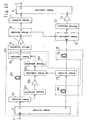
- Figure 14 is a block diagram of a feedforward amplifier capable of selecting which distortion suppression should be performed according to which system.
- the feedforward amplifier shown in Figure 14 has a configuration similar to that of the feedforward amplifier of aforementioned Embodiment 2 (see Figure 3), and is characterized by including a pilot signal oscillator 81' which is adjustable so that the oscillation frequency falls in the vicinity of a predetermined frequency range, a power divider (fourth power divider) 84' which divides the other portion of the output signal of a power divider 83, which inputs one portion of the output signal to a vector adjustor 12 , into three portions, a low frequency side distortion signal band pass filter 85' connected to the first output terminal of the power divider 84', a low frequency side distortion level detection circuit 86' that detects the signal level of the output signal of the low frequency side distortion signal band pass filter, a high frequency side distortion signal band pass filter 185 connected to the second output terminal of the power divider 84', a high frequency side distortion level detection circuit 186 that detects the signal level of the output signal of the high frequency side distortion signal band pass filter 185 , and a pilot signal
- the vector adjustor 69 of the pre-distortion circuit 6A is adjusted so that the signal level detected at the high frequency side distortion level detection circuit 186 reaches a minimum and the pilot signal oscillator 81' is adjusted so as to fall in the vicinity of the low frequency side and then the vector adjustor 12 is adjusted according to the signal level detected at the pilot level detection circuit 89.
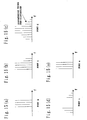
- the signal frequency spectra at the respective ports are as shown in Figures 15(a) to 15(e) in the first case and Figures 2(a) to 2(e) in the latter case as in the above-described case of Embodiment 2 (the distortion input by the pre-distortion circuit 6 differs between the two cases).
- the present invention is a program for allowing a computer to execute the functions of all or some means (or apparatuses, elements, circuits, sections, etc.) of the feedforward amplifier and communication apparatus, and is a program that operates in cooperation with the computer.
- the computer of the present invention is not limited to genuine hardware such as a CPU, but can also be firmware, OS or can include peripheral devices.
- the present invention is a program for allowing a computer to execute the operations of all or some steps (or processes, operations, actions, etc.) of the feedforward amplification method of the aforementioned embodiments and is a program that operates in cooperation with the computer.
- some means (or apparatuses, elements, circuits, sections, etc.) of the present invention and some steps (or processes, operations, actions, etc.) of the present invention refer to some means or steps within a plurality of means or steps or refer to some functions or some operations within one means or step.
- apparatuses or elements, circuits, sections, etc. of the present invention refer to some of a plurality of apparatuses or refer to some means (or elements, circuits, sections, etc.) within one apparatus or refer to some functions within one means.
- a computer-readable recording medium that records the program of the present invention is also included in the present invention.
- the mode of using the program of the present invention may also be a mode in which the program is recorded in a computer-readable recording medium and operates in cooperation with the computer.
- the mode of using the program of the present invention may also be a mode in which the program is transmitted through a transmission medium, read by a computer and operates in cooperation with the computer.
- examples of the recording medium include ROM, etc.
- examples of transmission medium include a transmission medium such as the Internet, light, radio wave and sound wave, etc.
- the configuration of the present invention may be implemented by software or by hardware.
- the present invention is a medium that carries a program for allowing a computer to execute the functions of all or some means of the feedforward amplifiers and communication apparatus of the aforementioned embodiments and is a medium whereby the computer-readable program and the program read by a computer executes the above-described functions in cooperation with the computer.
- the present invention is a medium that carries a program for allowing a computer to execute all or some operations in all or some steps of the feedforward amplification method of the aforementioned embodiments and is a medium whereby the computer-readable program and the program read by a computer executes the operations in cooperation with the computer.
- the distortion component generated on the high frequency side or low frequency side of the carrier band is mainly suppressed according to a feedforward system and the resulting deterioration in the amount of distortion suppression on the opposite side is compensated according to a pre-distortion system, it is possible to narrow the distortion compensation range according to pre-distortion system, suppress the distortion component efficiently and improve the amount of distortion suppression as a consequence.
- the level of distortion generated at the main amplifier is low, and therefore it is possible to carry out distortion suppression only according to a pre-distortion system, then stop the operation of the auxiliary amplifier 13 and thereby improve the efficiency during low output.
- the present invention has an advantage of providing a feedforward amplifier and communication apparatus capable of efficiently suppressing distortion components.
Landscapes
- Physics & Mathematics (AREA)
- Nonlinear Science (AREA)
- Engineering & Computer Science (AREA)
- Power Engineering (AREA)
- Amplifiers (AREA)
Abstract
Description
saidpre-distortion compensation circuit is adjusted so that suppression is performed on at least the distortion component generated within the frequency range other than said predetermined frequency range.
wherein stopping the operation of said auxiliary amplifier or the function of said pre-distortion compensation circuit based on said predetermined condition means that said control means stops the operation of said auxiliary amplifier when the signal level of said detected input signal is equal to or lower than a predetermined value.
wherein stopping the operation of said auxiliary amplifier or the function of said pre-distortion compensation circuit based on said predetermined condition means that said control means (1) stops the function of saidpre-distortion compensation circuit when the signal level of said detected input signal is equal to or lower than a first predetermined value and higher than a second predetermined value which is a value lower than said first predetermined value and (2) stops the operation of said auxiliary amplifier when the signal level of said input signal is equal to or lower than said second predetermined value.
Furthermore, since the auxiliary amplifier
Claims (31)
- A feedforward amplifier comprising:wherein said second vector adjustor is adjusted so that (1) suppression is performed on only the distortion component generated within a predetermined frequency range out of the range of frequencies to be suppressed in which distortion components to be suppressed occur or (2) the suppression of the distortion component generated within said predetermined frequency range is greater than the suppression of the distortion component generated within the frequency range other than said predetermined frequency range out of said range of frequencies to be suppressed, anda first power divider that divides an input signal into two portions;a first vector adjustor that adjusts the amplitude and phase of one portion of the output signal of said first power divider;a pre-distortion compensation circuit connected to said first vector adjustor;a main amplifier to amplify the output signal of said pre-distortion compensation circuit;a second power divider that divides the output signal of said main amplifier into two portions;a first delay circuit that delays the other portion of the output signal of said first power divider;a distortion detection power combiner that combines the one portion of the output signal of said second power divider and the output signal of said first delay circuit;a second delay circuit that delays the other portion of the output signal of said second power divider;a second vector adjustor that adjusts the amplitude and phase of the output signal of said distortion detection combiner;an auxiliary amplifier that amplifies the output signal of said second vector adjustor; anda distortion elimination power combiner that combines the output signal of said second delay circuit and the output signal of said auxiliary amplifier,
saidpre-distortion compensation circuit is adjusted so that suppression is performed on at least the distortion component generated within the frequency range other than said predetermined frequency range. - The feedforward amplifier according to claim 1, wherein said predetermined frequency range is the entire distortion signal band on the high frequency side or low frequency side generated at said main amplifier.
- The feedforward amplifier according to claim 1, wherein said pre-distortion compensation circuit is provided between said first power divider and said first vector adjustor.
- The feedforward amplifier according to claim 1, comprising:wherein the other portion of the output signal of said fifth power divider is supplied to the subsequent section.at least one pilot signal oscillator;a first power combiner that combines the output signal of said pilot signal oscillator and the output signal of said pre-distortion compensation circuit and outputs the combined signal to said main amplifier;a third power divider that divides the output signal of said distortion detection power combiner into two portions and inputs the one portion of the output signal to said second vector adjustor;a fourth power divider that divides the other portion of the output signal of said third power divider into two portions;a band pass filter connected to one output terminal of said fourth power divider;a distortion level detection circuit that detects the signal level of the output signal of said band pass filter;a carrier level detection circuit that detects the signal level of the other portion of the output signal of said fourth power divider;a fifth power divider that divides the output signal of said distortion elimination power combiner into two portions;a pilot level detection circuit that detects the signal level of one portion of the output signal of said fifth power divider; andcontrol means of automatically adjusting (1) said pre-distortion compensation circuit according to the signal level detected at said distortion level detection circuit, (2) said first vector adjustor according to the signal level detected at said carrier level detection circuit and (3) said second vector adjustor according to the signal level detected at said pilot level detection circuit,
- The feedforward amplifier according to claim 1, comprising:a third power divider that divides the output signal of said distortion detection power combiner into two portions and inputs the one portion of the output signal to said second vector adjustor;a fourth power divider that divides the other portion of the output signal of said third power divider into two portions;a band pass filter connected to one output terminal of said fourth power divider;a switch circuit that selects and switches between the output signal of said band pass filter and the other portion of the output signal of said fourth power divider according to a control signal from said control means;a signal level detection circuit that detects the signal level of said selected signal out of the output signal of said band pass filter and the other portion of the output signal of said fourth power divider; andcontrol means of automatically adjusting, based on the signal level detected at said signal level detection circuit, (1) said pre-distortion compensation circuit when the output signal of said band pass filter is selected and (2) said first vector adjustor when the other portion of the output signal of said fourth power divider is selected, respectively.
- The feedforward amplifier according to claim 4, wherein said control means stops the operation of said auxiliary amplifier or the function of said pre-distortion compensation circuit based on a predetermined condition.
- The feedforward amplifier according to claim 6, comprising input signal level detecting means of detecting the signal level of said input signal,
wherein stopping the operation of said auxiliary amplifier or the function of said pre-distortion compensation circuit based on said predetermined condition means that said control means stops the operation of said auxiliary amplifier when the signal level of said detected input signal is equal to or lower than a predetermined value. - The feedforward amplifier according to claim 6, comprising input signal level detecting means of detecting the signal level of said input signal, wherein stopping the operation of said auxiliary amplifier or the function of said pre-distortion compensation circuit based on said predetermined condition means that said control means stops the function of said pre-distortion compensation circuit when the signal level of said detected input signal is equal to or lower than a predetermined value.
- The feedforward amplifier according to claim 6, comprising input signal level detecting means of detecting the signal level of said input signal,
wherein stopping the operation of said auxiliary amplifier or the function of said pre-distortion compensation circuit based on said predetermined condition means that said control means (1) stops the function of saidpre-distortion compensation circuit when the signal level of said detected input signal is equal to or lower than a first predetermined value and higher than a second predetermined value which is a value lower than said first predetermined value and (2) stops the operation of said auxiliary amplifier when the signal level of said input signal is equal to or lower than said second predetermined value. - The feedforward amplifier according to claim 6, comprising:wherein stopping the function of said pre-distortion compensation circuit means connecting said first and second switch circuits to said transmission line side.a transmission line placed in parallel to said pre-distortion compensation circuit; andfirst and second switch circuits, placed,on the input side of said pre-distortion compensation circuit and said transmission line and on the output side of said pre-distortion compensation circuit and said transmission line, respectively to perform switching on said pre-distortion compensation circuit side and on said transmission line side,
- The feedforward amplifier according to any of claims 7 to 9, wherein said input signal level detecting means is provided on a signal line including the input signal component.
- The feedforward amplifier according to any of claims 1 to 10, wherein said pre-distortion compensation circuit comprising:a sixth power divider that divides a signal into two potions;a distortion generation circuit that generates distortion by inputting one portion of the output signal of said sixth power divider;a third vector adjustor that adjusts the amplitude and phase of the output signal of said distortion generation circuit;a third delay circuit that delays the other portion of the output signal of said sixth power divider; anda second power combiner that combines the output signal of said third vector adjustor and the output signal of said third delay circuit.
- The feedforward amplifier according to claim 12, wherein said distortion generation circuit comprising:a seventh power divider that divides a signal into two potions;a fourth vector adjustor that adjusts the amplitude and phase of one portion of the output signal of said seventh power divider;a distortion generation power amplifier that amplifies the output signal of said fourth vector adjustor;a fourth delay circuit that delays the other portion of the output signal of said seventh power divider; anda third power combiner that combines the output signal of said distortion generation power amplifier and the output of said fourth delay circuit.
- The feedforward amplifier according to claim 12, wherein automatically adjusting said pre-distortion compensation circuit according to the signal level detected by said distortion level detection circuit means adjusting the amplitude and phase of said third vector adjustor.
- The feedforward amplifier according to claim 12, wherein stopping the function of said pre-distortion compensation circuit means that the output signal from said distortion generation circuit is not input to said second power combiner.
- The feedforward amplifier according to claim 12, wherein said distortion generation circuit is constructed of only a distortion generation power amplifier for amplifying an input signal.
- The feedforward amplifier according to claim 12, wherein said third delay circuit is constructed using all or part of said first delay circuit.
- The feedforward amplifier according to claim 13, wherein said fourth delay circuit is constructed using all or part of said first delay circuit.
- The feedforward amplifier according to claim 13, wherein said distortion generation power amplifier is constructed of a non-linear device.
- The feedforward amplifier according to claim 1, wherein the distortion component generated within said predetermined frequency range is greater than distortion components generated in a frequency range other than said predetermined frequency range.
- The feedforward amplifier according to claim 1, wherein an adjustment is made so that the distortion component out of said distortion components to be suppressed, which is generated within the predetermined frequency range is greater than distortion components generated in a frequency range other than the predetermined frequency range.
- The feedforward amplifier according to claim 21, comprising:wherein the other portion of the output signal of said fifth power divider is supplied to the subsequent section.a pilot signal oscillator adjustable so that an oscillation frequency falls in the vicinity of said predetermined frequency range;a first power combiner that combines the output signal of said pilot signal oscillator and the output signal of said pre-distortion compensation circuit and outputs the combined signal to said main amplifier;a third power divider that divides the output signal of said distortion detection power combiner into two portions and inputs one portion of the output signal to said second vector adjustor;a fourth power divider that divides the other portion of the output signal of said third power divider into three portions;a low frequency side distortion signal band pass filter connected to the first output terminal of said fourth power divider;a low frequency side distortion level detection circuit that detects the signal level of the output signal of said low frequency side distortion signal band pass filter;a high frequency side distortion signal band pass filter connected to the second output terminal of said fourth power divider;a high frequency side distortion level detection circuit that detects the signal level of the output signal of said high frequency side distortion signal band pass filter;a carrier level detection circuit that detects the signal level of the third output signal of said fourth power divider;a fifth power divider that divides the output signal of said distortion elimination power combiner into two portions;a pilot level detection circuit that detects the signal level of the other portion of the output signal of said fifth power divider; andcontrol means of automatically adjusting (1) said pre-distortion compensation circuit and pilot signal oscillator according to the signal level detected at said low frequency side distortion level detection circuit and the signal level detected at said high frequency side distortion level detection circuit, (2) said first vector adjustor according to the signal level detected at said carrier level detection circuit and (3) said second vector adjustor according to the signal level detected at said pilot level detection circuit, respectively,
- The feedforward amplifier according to claim 22, wherein said pre-distortion compensation circuit and pilot signal oscillator are automatically adjusted (a) when the signal level detected at said low frequency side distortion level detection circuit is greater than the signal level detected at said high frequency side distortion level detection circuit, in such a way that said predetermined frequency range becomes the frequency range corresponding to said low frequency side and (b) when the signal level detected at said high frequency side distortion level detection circuit is greater than the signal level detected at said low frequency side distortion level detection circuit, in such a way that said predetermined frequency range becomes the frequency range corresponding to said high frequency side.
- A feedforward amplifier comprising:wherein said second vector adjustor is adjusted so that (1) suppression is performed on only the distortion component generated within a predetermined frequency range out of the range of frequencies to be suppressed in which distortion components to be suppressed occur or (2) the suppression of the distortion component generated within said predetermined frequency range is greater than the suppression of the distortion component generated within the frequency range other than said predetermined frequency range out of said range of frequencies to be suppressed.a first power divider that divides an input signal into two portions;a first vector adjustor that adjusts the amplitude and phase of one portion of the output signal of said first power divider;a main amplifier to amplify the output signal of said first vector adjustor;a second power divider that divides the output signal of said main amplifier into two portions;a first delay circuit that delays the other portion of the output signal of said first power divider;a distortion detection power combiner that combines the one portion of the output signal of said second power divider and the output signal of said first delay circuit;a second delay circuit that delays the other portion of the output signal of said second power divider;a second vector adjustor that adjusts the amplitude and phase of the output signal of said distortion detection combiner;an auxiliary amplifier that amplifies the output signal of said second vector adjustor; anda distortion elimination power combiner that combines the output signal of said second delay circuit and the output signal of said auxiliary amplifier,
- A communication apparatus using the feedforward amplifier according to any of claims 1 to 24.
- A feedforward amplification method comprising:a step of dividing an input signal into two portions using a first power divider;a step of adjusting the amplitude and phase of one portion of the output signal of said first power divider using a first vector adjustor;a step of amplifying the output signal of said pre-distortion compensation circuit connected to said first vector adjustor using a main amplifier;a step of dividing the output signal of said main amplifier into two portions using a second power divider;a step of delaying the other portion of the output signal of said first power divider using a first delay circuit;a step of combining the one portion of the output signal of said second power divider and the output signal of said first delay circuit using a distortion detection power combiner;a step of delaying the other portion of the output signal of said second power divider using a second delay circuit;a step of adjusting the amplitude and phase of the output signal of said distortion detection combiner using a second vector adjustor;a step of amplifying the output signal of said second vector adjustor using an auxiliary amplifier;a step of combining the output signal of said second delay circuit and the output signal of said auxiliary amplifier using a distortion elimination power combiner;a step of adjusting said second vector adjustor so that (1) suppression is performed on only the distortion component generated within a predetermined frequency range out of the range of frequencies to be suppressed in which distortion components to be suppressed occur or (2) the suppression of the distortion component generated within said predetermined frequency range is greater than the suppression of the distortion component generated within the frequency range other than said predetermined frequency range out of said range of frequencies to be suppressed; anda step of adjusting said pre-distortion compensation circuit so that at least the distortion component generated in a frequency range other than said predetermined frequency range is suppressed.
- A feedforward amplification method comprising:a step of dividing an input signal into two portions using a first power divider;a step of adjusting the amplitude and phase of one portion of the output signal of said first power divider using a first vector adjustor;a step of amplifying the output signal of said first vector adjustor using a main amplifier;a step of dividing the output signal of said main amplifier into two portions using a second power divider;a step of delaying the other portion of the output signal of said first power divider using a first delay circuit;a step of combining the one portion of the output signal of said second power divider and the output signal of said first delay circuit using a distortion detection power combiner;a step of delaying the other portion of the output signal of said second power divider using a second delay circuit;a step of adjusting the amplitude and phase of the output signal of said distortion detection combiner using a second vector adjustor;a step of amplifying the output signal of said second vector adjustor using an auxiliary amplifier;a step of combining the output signal of said second delay circuit and the output signal of said auxiliary amplifier using a distortion elimination power combiner; anda step of adjusting said second vector adjustor so that (1) suppression is performed on only the distortion component generated within a predetermined frequency range out of the range of frequencies to be suppressed in which distortion components to be suppressed occur or (2) the suppression of the distortion component generated within said predetermined frequency range is greater than the suppression of the distortion component generated within the frequency range other than said predetermined frequency range out of said range of frequencies to be suppressed.
- A program for allowing a computer to execute all or some of the steps of the feedforward amplification method according to claim 26, comprising:a step of dividing an input signal into two portions using a first power divider;a step of adjusting the amplitude and phase of one portion of the output signal of said first power divider using a first vector adjustor;a step of amplifying the output signal of said pre-distortion compensation circuit connected to said first vector adjustor using a main amplifier;a step of dividing the output signal of said main amplifier into two portions using a second power divider;a step of delaying the other portion of the output signal of said first power divider using a first delay circuit;a step of combining the one portion of the output signal of said second power divider and the output signal of said first delay circuit using a distortion detection power combiner;a step of delaying the other portion of the output signal of said second power divider using a second delay circuit;a step of adjusting the amplitude and phase of the output signal of said distortion detection combiner using a second vector adjustor;a step of amplifying the output signal of said second vector adjustor using an auxiliary amplifier;a step of combining the output signal of said second delay circuit and the output signal of said auxiliary amplifier using a distortion elimination power combiner;a step of adjusting said second vector adjustor so that (1) suppression is performed on only the distortion component generated within a predetermined frequency range out of the range of frequencies to be suppressed in which distortion components to be suppressed occur or (2) the suppression of the distortion component generated within said predetermined frequency range is greater than the suppression of the distortion component generated within the frequency range other than said predetermined frequency range out of said range of frequencies to be suppressed; anda step of adjusting said pre-distortion compensation circuit so that at least the distortion component generated in a frequency range other than said predetermined frequency range is suppressed.
- A computer-processable medium that stores a program for allowing a computer to execute all or some of the steps of the feedforward amplification method according to claim 26, comprising:a step of dividing an input signal into two portions using a first power divider;a step of adjusting the amplitude and phase of one portion of the output signal of said first power divider using a first vector adjustor;a step of amplifying the output signal of said pre-distortion compensation circuit connected to said first vector adjustor using a main amplifier;a step of dividing the output signal of said main amplifier into two portions using a second power divider;a step of delaying the other portion of the output signal of said first power divider using a first delay circuit;a step of combining the one portion of the output signal of said second power divider and the output signal of said first delay circuit using a distortion detection power combiner;a step of delaying the other portion of the output signal of said second power divider using a second delay circuit;a step of adjusting the amplitude and phase of the output signal of said distortion detection combiner using a second vector adjustor;a step of amplifying the output signal of said second vector adjustor using an auxiliary amplifier;a step of combining the output signal of said second delay circuit and the output signal of said auxiliary amplifier using a distortion elimination power combiner;a step of adjusting said second vector adjustor so that (1) suppression is performed on only the distortion component generated within a predetermined frequency range out of the range of frequencies to be suppressed in which distortion components to be suppressed occur or (2) the suppression of the distortion component generated within said predetermined frequency range is greater than the suppression of the distortion component generated within the frequency range other than said predetermined frequency range out of said range of frequencies to be suppressed; anda step of adjusting said pre-distortion compensation circuit so that at least the distortion component generated in a frequency range other than said predetermined frequency range is suppressed.
- A program for allowing a computer to execute all or some of the steps of the feedforward amplification method according to claim 27, comprising:a step of dividing an input signal into two portions using a first power divider;a step of adjusting the amplitude and phase of one portion of the output signal of said first power divider using a first vector adjustor;a step of amplifying the output signal of said first vector adjustor using a main amplifier ;a step of dividing the output signal of said main amplifier into two portions using a second power divider;a step of delaying the other portion of the output signal of said first power divider using a first delay circuit;a step of combining the one portion of the output signal of said second power divider and the output signal of said first delay circuit using a distortion detection power combiner;a step of delaying the other portion of the output signal of said second power divider using a second delay circuit;a step of adjusting the amplitude and phase of the output signal of said distortion detection combiner using a second vector adjustor;a step of amplifying the output signal of said second vector adjustor using an auxiliary amplifier;a step of combining the output signal of said second delay circuit and the output signal of said auxiliary amplifier using a distortion elimination power combiner; anda step of adjusting said second vector adjustor so that (1) suppression is performed on only the distortion component generated within a predetermined frequency range out of the range of frequencies to be suppressed in which distortion components to be suppressed occur or (2) the suppression of the distortion component generated within said predetermined frequency range is greater than the suppression of the distortion component generated within the frequency range other than said predetermined frequency range out of said range of frequencies to be suppressed.
- A computer-processable medium that stores a program for allowing a computer to execute all or some of the steps of the feedforward amplification method according to claim 27, comprising:a step of dividing an input signal into two portions using a first power divider ;a step of adjusting the amplitude and phase of one portion of the output signal of said first power divider using a first vector adjustor;a step of amplifying the output signal of said first vector adjustor using a main amplifier;a step of dividing the output signal of said main amplifier into two portions using a second power divider;a step of delaying the other portion of the output signal of said first power divider using a first delay circuit;a step of combining the one portion of the output signal of said second power divider and the output signal of said first delay circuit using a distortion detection power combiner;a step of delaying the other portion of the output signal of said second power divider using a second delay circuit;a step of adjusting the amplitude and phase of the output signal of said distortion detection combiner using a second vector adjustor;a step of amplifying the output signal of said second vector adjustor using an auxiliary amplifier;a step of combining the output signal of said second delay circuit and the output signal of said auxiliary amplifier using a distortion elimination power combiner; anda step of adjusting said second vector adjustor so that (1) suppression is performed on only the distortion component generated within a predetermined frequency range out of the range of frequencies to be suppressed in which distortion components to be suppressed occur or (2) the suppression of the distortion component generated within said predetermined frequency range is greater than the suppression of the distortion component generated within the frequency range other than said predetermined frequency range out of said range of frequencies to be suppressed.
Applications Claiming Priority (3)
| Application Number | Priority Date | Filing Date | Title |
|---|---|---|---|
| JP2000369147 | 2000-12-04 | ||
| JP2000369147 | 2000-12-04 | ||
| PCT/JP2001/010469 WO2002050997A1 (en) | 2000-12-04 | 2001-11-30 | Feedforward amplifier, communication apparatus, feedforward amplifying method, program and medium |
Publications (3)
| Publication Number | Publication Date |
|---|---|
| EP1353438A1 true EP1353438A1 (en) | 2003-10-15 |
| EP1353438A4 EP1353438A4 (en) | 2004-11-17 |
| EP1353438B1 EP1353438B1 (en) | 2008-08-06 |
Family
ID=18839231
Family Applications (1)
| Application Number | Title | Priority Date | Filing Date |
|---|---|---|---|
| EP01271109A Expired - Lifetime EP1353438B1 (en) | 2000-12-04 | 2001-11-30 | Feedforward amplifier, communication apparatus, feedforward amplifying method, program and medium |
Country Status (4)
| Country | Link |
|---|---|
| US (1) | US6940346B2 (en) |
| EP (1) | EP1353438B1 (en) |
| DE (1) | DE60135249D1 (en) |
| WO (1) | WO2002050997A1 (en) |
Cited By (1)
| Publication number | Priority date | Publication date | Assignee | Title |
|---|---|---|---|---|
| EP2178206A2 (en) | 2008-10-17 | 2010-04-21 | Fraunhofer-Gesellschaft zur Förderung der angewandten Forschung e.V. | Feed-forward amplifier with device for creating a correction signal |
Families Citing this family (5)
| Publication number | Priority date | Publication date | Assignee | Title |
|---|---|---|---|---|
| US7095799B2 (en) * | 2002-04-29 | 2006-08-22 | Agilent Technologies, Inc. | Systems and methods for providing baseband-derived predistortion to increase efficiency of transmitters |
| JP4598414B2 (en) * | 2004-02-27 | 2010-12-15 | 株式会社エヌ・ティ・ティ・ドコモ | Control method and apparatus for power series predistorter |
| US7756493B2 (en) * | 2005-04-05 | 2010-07-13 | Powerwave Technologies, Inc. | Feed forward amplifier system and method using the pilot frequency from a positive feedback pilot generation and detection circuit to improve second loop convergence |
| JP4896424B2 (en) * | 2005-04-22 | 2012-03-14 | 株式会社日立国際電気 | Distortion compensation amplifier |
| EP2232413B1 (en) * | 2007-12-05 | 2012-06-20 | Wavelogics AB | Data carrier device |
Family Cites Families (11)
| Publication number | Priority date | Publication date | Assignee | Title |
|---|---|---|---|---|
| JPH0785523B2 (en) | 1988-02-05 | 1995-09-13 | 日本電信電話株式会社 | Non-linear distortion compensation circuit |
| RU2142670C1 (en) | 1995-11-16 | 1999-12-10 | Самсунг Электроникс Ко., Лтд. | Device for linear power amplification |
| KR100217416B1 (en) | 1995-11-16 | 1999-09-01 | 윤종용 | Linear amplifier and method thereof |
| US5760646A (en) | 1996-03-29 | 1998-06-02 | Spectrian | Feed-forward correction loop with adaptive predistortion injection for linearization of RF power amplifier |
| JP3064901B2 (en) | 1996-05-08 | 2000-07-12 | 日本電気株式会社 | Feed forward amplifier |
| JP3106996B2 (en) | 1997-04-02 | 2000-11-06 | 日本電気株式会社 | Feed forward amplification circuit |
| CA2281209A1 (en) | 1998-10-30 | 2000-04-30 | Norman Gerard Ziesse | Feedforward amplifier and method of amplifying signals |
| JP2000151295A (en) | 1998-11-05 | 2000-05-30 | Mitsubishi Electric Corp | Distortion compensation circuit |
| JP3371837B2 (en) | 1999-01-28 | 2003-01-27 | 日本電気株式会社 | Feedforward amplifier and amplification method thereof |
| JP2001053552A (en) | 1999-08-10 | 2001-02-23 | Nec Corp | Feed-forward amplifier circuit and method for compensating nonlinear distortion in the same |
| US6590449B2 (en) * | 2000-05-30 | 2003-07-08 | Matsushita Electric Industrial Co., Ltd. | Predistortion circuit, low-distortion power amplifier, and control methods therefor |
-
2001
- 2001-11-30 DE DE60135249T patent/DE60135249D1/en not_active Expired - Fee Related
- 2001-11-30 US US10/433,582 patent/US6940346B2/en not_active Expired - Fee Related
- 2001-11-30 WO PCT/JP2001/010469 patent/WO2002050997A1/en not_active Ceased
- 2001-11-30 EP EP01271109A patent/EP1353438B1/en not_active Expired - Lifetime
Cited By (3)
| Publication number | Priority date | Publication date | Assignee | Title |
|---|---|---|---|---|
| EP2178206A2 (en) | 2008-10-17 | 2010-04-21 | Fraunhofer-Gesellschaft zur Förderung der angewandten Forschung e.V. | Feed-forward amplifier with device for creating a correction signal |
| DE102008052172A1 (en) | 2008-10-17 | 2010-04-22 | Fraunhofer-Gesellschaft zur Förderung der angewandten Forschung e.V. | Device for generating a correction signal |
| US7940106B2 (en) | 2008-10-17 | 2011-05-10 | Fraunhofer-Gesellschaft Zur Foerderung Der Angewandten Forschung E.V. | Apparatus for generating a correction signal |
Also Published As
| Publication number | Publication date |
|---|---|
| EP1353438A4 (en) | 2004-11-17 |
| US6940346B2 (en) | 2005-09-06 |
| DE60135249D1 (en) | 2008-09-18 |
| WO2002050997A1 (en) | 2002-06-27 |
| EP1353438B1 (en) | 2008-08-06 |
| US20040075497A1 (en) | 2004-04-22 |
Similar Documents
| Publication | Publication Date | Title |
|---|---|---|
| EP1158661B1 (en) | Feed-forward amplifier | |
| US6242979B1 (en) | Linearization using parallel cancellation in linear power amplifier | |
| EP1959565A1 (en) | High efficiency amplifier | |
| KR100259849B1 (en) | Feedforward Linear Power Amplification Using Pilot Tone Hopping | |
| US6710652B2 (en) | Feedforward amplifier | |
| US7133466B2 (en) | Amplifying apparatus | |
| EP1353438A1 (en) | Feedforward amplifier, communication apparatus, feedforward amplifying method, program and medium | |
| JPWO2010076845A1 (en) | Polar modulation device and communication device | |
| KR101023258B1 (en) | Linearization Method of Transmitter and Transmitter in Digital Wireless Transceiver System | |
| JP2001237651A (en) | Power amplifier | |
| KR100371531B1 (en) | Feedforward linear power amplifier using error feedback | |
| JP2008172511A (en) | Distortion compensation amplifier | |
| JP2008236641A (en) | Transmitter | |
| JP2010226249A (en) | Amplifier | |
| JP2005012419A (en) | Amplifier | |
| KR100519700B1 (en) | Optimized loop control method for a linear power amplifier | |
| JP2002237727A (en) | Feedforward amplifier, communication device, feedforward amplification method, program, and medium | |
| JP2004320185A (en) | Predistortion compensation power amplifier | |
| JP4439868B2 (en) | amplifier | |
| JP3562472B2 (en) | Feed forward amplifier | |
| JP2003209476A (en) | Communication terminal and its control circuit | |
| JP2009296237A (en) | Interference remover, and communication apparatus | |
| JP2006279633A (en) | Distortion compensator and its distortion compensation method | |
| JP2002171135A (en) | Feed forward amplifier | |
| JP2004032594A (en) | Communication device |
Legal Events
| Date | Code | Title | Description |
|---|---|---|---|
| PUAI | Public reference made under article 153(3) epc to a published international application that has entered the european phase |
Free format text: ORIGINAL CODE: 0009012 |
|
| 17P | Request for examination filed |
Effective date: 20030516 |
|
| AK | Designated contracting states |
Kind code of ref document: A1 Designated state(s): AT BE CH CY DE DK ES FI FR GB GR IE IT LI LU MC NL PT SE TR |
|
| AX | Request for extension of the european patent |
Extension state: AL LT LV MK RO SI |
|
| RBV | Designated contracting states (corrected) |
Designated state(s): DE FR GB |
|
| A4 | Supplementary search report drawn up and despatched |
Effective date: 20041005 |
|
| 17Q | First examination report despatched |
Effective date: 20060508 |
|
| GRAP | Despatch of communication of intention to grant a patent |
Free format text: ORIGINAL CODE: EPIDOSNIGR1 |
|
| GRAS | Grant fee paid |
Free format text: ORIGINAL CODE: EPIDOSNIGR3 |
|
| GRAA | (expected) grant |
Free format text: ORIGINAL CODE: 0009210 |
|
| AK | Designated contracting states |
Kind code of ref document: B1 Designated state(s): DE FR GB |
|
| REG | Reference to a national code |
Ref country code: GB Ref legal event code: FG4D |
|
| REF | Corresponds to: |
Ref document number: 60135249 Country of ref document: DE Date of ref document: 20080918 Kind code of ref document: P |
|
| RAP2 | Party data changed (patent owner data changed or rights of a patent transferred) |
Owner name: PANASONIC CORPORATION |
|
| PGFP | Annual fee paid to national office [announced via postgrant information from national office to epo] |
Ref country code: DE Payment date: 20081223 Year of fee payment: 8 |
|
| PLBE | No opposition filed within time limit |
Free format text: ORIGINAL CODE: 0009261 |
|
| STAA | Information on the status of an ep patent application or granted ep patent |
Free format text: STATUS: NO OPPOSITION FILED WITHIN TIME LIMIT |
|
| PGFP | Annual fee paid to national office [announced via postgrant information from national office to epo] |
Ref country code: GB Payment date: 20081119 Year of fee payment: 8 |
|
| 26N | No opposition filed |
Effective date: 20090507 |
|
| REG | Reference to a national code |
Ref country code: FR Ref legal event code: ST Effective date: 20090731 |
|
| GBPC | Gb: european patent ceased through non-payment of renewal fee |
Effective date: 20091130 |
|
| PG25 | Lapsed in a contracting state [announced via postgrant information from national office to epo] |
Ref country code: DE Free format text: LAPSE BECAUSE OF NON-PAYMENT OF DUE FEES Effective date: 20100601 |
|
| PG25 | Lapsed in a contracting state [announced via postgrant information from national office to epo] |
Ref country code: GB Free format text: LAPSE BECAUSE OF NON-PAYMENT OF DUE FEES Effective date: 20091130 |
|
| PG25 | Lapsed in a contracting state [announced via postgrant information from national office to epo] |
Ref country code: FR Free format text: LAPSE BECAUSE OF NON-PAYMENT OF DUE FEES Effective date: 20081130 |