EP1354662A1 - Appareil de soudage par friction - Google Patents
Appareil de soudage par friction Download PDFInfo
- Publication number
- EP1354662A1 EP1354662A1 EP03290806A EP03290806A EP1354662A1 EP 1354662 A1 EP1354662 A1 EP 1354662A1 EP 03290806 A EP03290806 A EP 03290806A EP 03290806 A EP03290806 A EP 03290806A EP 1354662 A1 EP1354662 A1 EP 1354662A1
- Authority
- EP
- European Patent Office
- Prior art keywords
- workpieces
- pressing
- burrs
- rotary
- welding apparatus
- Prior art date
- Legal status (The legal status is an assumption and is not a legal conclusion. Google has not performed a legal analysis and makes no representation as to the accuracy of the status listed.)
- Withdrawn
Links
- 238000003466 welding Methods 0.000 title claims abstract description 23
- 238000003825 pressing Methods 0.000 claims abstract description 32
- 239000000463 material Substances 0.000 description 20
- 238000005520 cutting process Methods 0.000 description 5
- 229910000831 Steel Inorganic materials 0.000 description 2
- 230000004323 axial length Effects 0.000 description 2
- 238000004080 punching Methods 0.000 description 2
- 239000010959 steel Substances 0.000 description 2
- 229910001566 austenite Inorganic materials 0.000 description 1
- 238000002485 combustion reaction Methods 0.000 description 1
- 229910000734 martensite Inorganic materials 0.000 description 1
- 238000000034 method Methods 0.000 description 1
- 238000012986 modification Methods 0.000 description 1
- 230000004048 modification Effects 0.000 description 1
Images


Classifications
-
- B—PERFORMING OPERATIONS; TRANSPORTING
- B23—MACHINE TOOLS; METAL-WORKING NOT OTHERWISE PROVIDED FOR
- B23K—SOLDERING OR UNSOLDERING; WELDING; CLADDING OR PLATING BY SOLDERING OR WELDING; CUTTING BY APPLYING HEAT LOCALLY, e.g. FLAME CUTTING; WORKING BY LASER BEAM
- B23K20/00—Non-electric welding by applying impact or other pressure, with or without the application of heat, e.g. cladding or plating
- B23K20/12—Non-electric welding by applying impact or other pressure, with or without the application of heat, e.g. cladding or plating the heat being generated by friction; Friction welding
- B23K20/1205—Non-electric welding by applying impact or other pressure, with or without the application of heat, e.g. cladding or plating the heat being generated by friction; Friction welding using translation movement
-
- B—PERFORMING OPERATIONS; TRANSPORTING
- B23—MACHINE TOOLS; METAL-WORKING NOT OTHERWISE PROVIDED FOR
- B23K—SOLDERING OR UNSOLDERING; WELDING; CLADDING OR PLATING BY SOLDERING OR WELDING; CUTTING BY APPLYING HEAT LOCALLY, e.g. FLAME CUTTING; WORKING BY LASER BEAM
- B23K37/00—Auxiliary devices or processes, not specially adapted for a procedure covered by only one of the other main groups of this subclass
- B23K37/06—Auxiliary devices or processes, not specially adapted for a procedure covered by only one of the other main groups of this subclass for positioning the molten material, e.g. confining it to a desired area
Definitions
- the present invention relates to a friction welding apparatus for welding between different materials such as stems of a poppet valve.
- valve head is made of austenite heat-resistant steel
- valve stem is made of martensite heat-resistant steel. They are welded to each other.
- the friction welding apparatus “A” comprises a rotary holder 2 fixed on a base 1, and a fixing holder 3 which moves from side to side reciprocally on the base 1 by a hydraulic cylinder (not shown).
- a collet-type rotary chuck 2a and a fixing chuck 3a are mounted on opposing surfaces of the holders 2 and 3 respectively.
- a stem material 4 for a poppet valve is held by the rotary chuck 2a, and a head material 5 is held by the fixing chuck 3a so that opposing ends of the materials 4,5 may project at a predetermined distance. Then, while the rotary chuck 2a is rotated at high speed, the fixing holder 3 is moved rightward, and the end faces of the materials 4,5 are pressed under suitable pressure. The end faces are melted by friction heat, so that the materials 4,5 are welded to each other.
- C-sectioned weld burrs 6,6 are formed on welded portion as shown in Fig. 10.
- the burrs 6 are removed by a grinding wheel 7, portions which are adhered on the outer circumferential surface of the stem remain, and are put between the grinding wheel 7 and the stem, thereby damaging the outer circumferential surface of the stem.
- axial lengths of the burrs 6 are relatively larger, which requires use of the large-width grinding wheel 7 to result in increase in cost.
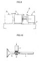
- the burrs 6 are removed by a press as shown in Fig. 11.
- the burrs 6 are supported by a sharing blade 8a of a circular die 8 which is dividable right and left, and strongly pressed on the top by a punch 9.
- the burrs 6 are removed by punching, but slightly larger stepped portions are formed on the outer circumferential surface of bound portion as shown in Fig. 12.
- the internal diameter of the blade 8a is determined equal to the external diameter of the stem, the diameter of the bound portion may become smaller than the external diameter when the burrs 6 are cut off by punching.
- the internal diameter of the blade 8a is set to a diameter slightly larger than the axial diameter, which generates the stepped portions of the bound portion.
- the stepped portions of the bound portion must be cut off using a cutting tool or a grinding wheel, thereby increasing the number of working steps to cause decrease in productivity.
- a friction welding apparatus comprising a rotary holder; a fixing holder which faces said rotary holder axially; a rotary chuck provided on said rotary holder; a fixing chuck provided on said fixing holder, a first workpiece held in a rotary chuck being rotated and pressed towards a second workpiece held in said fixing chuck so that the first workpiece may be bound with the second workpiece with friction heat; and pressing means having pressing surfaces which faces each other axially via a clearance in which weld burrs generated at a bound portion of the first and second workpieces can be inserted between said pressing surfaces, thereby preventing the burrs from expanding axially.
- FIGs. 1 and 2 illustrate the first embodiment of the present invention.
- a friction welding apparatus 10 comprises a rotary holder 2 and a fixing holder 3 which have a rotary chuck 2a and a fixing chuck 3a respectively.
- Annular pressing portions 11,11 having axial bores 11a,11a are provided on the rotary and fixing chucks 2a,3a to expand and shrink radially together with the chucks 2a,3a.
- the annular pressing portions 11,11 are separable into a number of divisions circumferentially.
- the materials 4,5 are held between the rotary and fixing chucks 2a and 3a so that the opposing ends may project from pressing surfaces 11b,11b of the blocks 11,11.
- the materials 4,5 are slightly longer than what are welded to form burrs during welding.
- the engaged surfaces are welded to generate weld burrs 6,6.
- a clearance between the pressing surfaces 11b,11b of the pressing portions 11,11 becomes smaller.
- the burrs 6 are prevented from expanding axially and enlarged radially perpendicular to the axis in the clearance between the pressing portions 11,11.
- the axial lengths of the burrs 6 become smaller, and the burrs 6 can be easily removed without damaging the outer circumferential surface of the stem using a smaller-width inexpensive grinding wheel 7 as shown in Fig. 3. Also the burrs 6 can be easily removed by a cutting tool.
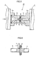
- Figs. 4 and 5 illustrate the second embodiment of a friction welding apparatus 12 of the present invention, in which the pressing surfaces of pressing portions 11,11 are inclined to fit in shape with each other, which is different from the foregoing embodiment.
- a concave surface 13 is formed, and at the end of the right-hand pressing portion 11, a convex surface 14 is formed.
- weld burrs 6,6 are bent by the inclined surfaces 13,14 between the pressing portions 11 and 11 and extended radially as shown in Fig. 5.
- the burrs 6 are prevented from expanding axially as well as the first embodiment.
- the burrs 6 can be easily cut off by a grinding wheel or a cutting tool.
- a narrower grinding wheel 7 is moved along the outer circumferential surface, so that the bases of the burrs 6 can be cut off as rings.
- the inclined surfaces 13,14 of the pressing portions 11 may be oppositely inclined so that the burrs 6 may be inclined leftward.
- Figs. 7 and 8 illustrate the third embodiment of the present invention, in which means for pressing burrs are separately provided from chucks 2a,3a.
- a pair of pressing members 17,17 each consisting of semi-circular disc which has a semi-circular groove 16 slightly larger than radii of materials 4,5.
- the pressing members 17 are connected to reciprocating means such as a hydraulic cylinder (not shown), so that the members can go toward and away from a connected portion of the materials 4,5.
- the pressing members 17,17 goes towards the materials 4,5.
- the materials 4,5 are engaged with each other, so that generated weld burrs 6,6 are inserted in the semi-circular grooves 15,15 and pressed, so that the materials 4,5 cannot be expanded axially.
- the present invention may be applied to binding of ordinary workpieces.
Landscapes
- Engineering & Computer Science (AREA)
- Mechanical Engineering (AREA)
- Physics & Mathematics (AREA)
- Optics & Photonics (AREA)
- Pressure Welding/Diffusion-Bonding (AREA)
Applications Claiming Priority (2)
| Application Number | Priority Date | Filing Date | Title |
|---|---|---|---|
| JP2002117025A JP2003311437A (ja) | 2002-04-19 | 2002-04-19 | 摩擦溶接装置 |
| JP2002117025 | 2002-04-19 |
Publications (1)
| Publication Number | Publication Date |
|---|---|
| EP1354662A1 true EP1354662A1 (fr) | 2003-10-22 |
Family
ID=28672673
Family Applications (1)
| Application Number | Title | Priority Date | Filing Date |
|---|---|---|---|
| EP03290806A Withdrawn EP1354662A1 (fr) | 2002-04-19 | 2003-03-31 | Appareil de soudage par friction |
Country Status (5)
| Country | Link |
|---|---|
| US (1) | US20030197047A1 (fr) |
| EP (1) | EP1354662A1 (fr) |
| JP (1) | JP2003311437A (fr) |
| KR (1) | KR20030083574A (fr) |
| CN (1) | CN1451509A (fr) |
Cited By (4)
| Publication number | Priority date | Publication date | Assignee | Title |
|---|---|---|---|---|
| US8393521B1 (en) | 2011-12-20 | 2013-03-12 | Caterpillar Inc. | Flash ring separator |
| EP2960004A1 (fr) * | 2014-05-22 | 2015-12-30 | ArvinMeritor Technology, LLC | Système et procédé de soudage par friction d'une pièce à usiner |
| WO2018024718A1 (fr) * | 2016-08-01 | 2018-02-08 | Kuka Industries Gmbh | Soudage par friction et cisaillement du bourrelet de soudure combinés |
| EP2650075B1 (fr) * | 2010-11-25 | 2022-01-19 | Nittan Valve Co., Ltd. | Dispositif d'ébavurage pour machine à souder par friction |
Families Citing this family (17)
| Publication number | Priority date | Publication date | Assignee | Title |
|---|---|---|---|---|
| KR101349287B1 (ko) * | 2007-10-30 | 2014-01-16 | 재단법인 포항산업과학연구원 | 금속 박판 제조방법 |
| CN101598654B (zh) * | 2008-11-21 | 2010-12-01 | 西北工业大学 | 一种摩擦焊接头塑性变形的物理模拟方法 |
| CN102896433A (zh) * | 2012-10-17 | 2013-01-30 | 国家电网公司 | 一种柱状件自动焊接方法 |
| CN104014928A (zh) * | 2014-06-19 | 2014-09-03 | 西安特种设备检验检测院 | 一种马氏体耐热钢和奥氏体耐热钢的异种钢的焊接方法 |
| DE202014105434U1 (de) * | 2014-11-12 | 2016-02-15 | Kuka Systems Gmbh | Pressschweißvorrichtung |
| CN104439690A (zh) * | 2014-11-24 | 2015-03-25 | 福斯流体控制(苏州)有限公司 | 应用于阀杆的压力焊方法 |
| CN107538129B (zh) * | 2016-06-29 | 2020-06-23 | 中国航空制造技术研究院 | 一种回填式搅拌摩擦点焊焊后粘料分离装置 |
| US11536311B2 (en) * | 2017-03-07 | 2022-12-27 | Neapco Intellectual Property Holdings, Llc | Integrated post-weld knurling process and device for performing the same |
| JP6951128B2 (ja) * | 2017-06-12 | 2021-10-20 | 日本スピンドル製造株式会社 | 部材接合方法及び回転塑性加工装置 |
| CN109175672B (zh) * | 2018-11-05 | 2020-08-04 | 中国航空制造技术研究院 | 线性摩擦焊接过程中飞边变形控制装置及方法 |
| KR102084949B1 (ko) * | 2019-04-30 | 2020-03-05 | 에이에프더블류 주식회사 | 부스바 제조방법 |
| JP7261678B2 (ja) * | 2019-07-04 | 2023-04-20 | シチズン時計株式会社 | 工作機械及び加工方法 |
| CN114450119A (zh) * | 2019-09-26 | 2022-05-06 | 日立安斯泰莫株式会社 | 杆的制造方法 |
| CN111408912B (zh) * | 2020-05-14 | 2021-08-20 | 中国兵器工业第五九研究所 | 一种小直径窄间隙薄壁多叶片构件的制备方法及夹持工装 |
| CN113843497B (zh) * | 2021-09-23 | 2022-12-20 | 无锡亨通特种合金制造有限公司 | 一种薄壁管件摩擦焊的焊缝处理系统 |
| CN114043068B (zh) * | 2021-10-22 | 2023-02-28 | 中国航空制造技术研究院 | 一种线性摩擦焊接头飞边成形控制方法 |
| CN114433998B (zh) * | 2022-03-25 | 2023-04-14 | 南通重矿金属新材料有限公司 | 一种金属材料的搅拌摩擦、挤压复合装置 |
Citations (6)
| Publication number | Priority date | Publication date | Assignee | Title |
|---|---|---|---|---|
| US3259969A (en) * | 1963-01-22 | 1966-07-12 | Central Cable Corp | Method of making butt welded joints |
| US3452914A (en) * | 1962-07-09 | 1969-07-01 | Caterpillar Tractor Co | Apparatus for controlling flash during friction bonding |
| FR2096924A7 (fr) * | 1970-07-16 | 1972-03-03 | Caterpillar Tractor Co | |
| US3853258A (en) * | 1972-07-17 | 1974-12-10 | Textron Inc | Flash removal apparatus for a friction welding operation |
| JPS6160283A (ja) * | 1984-08-31 | 1986-03-27 | Fuji Valve Kk | エンジンバルブの製造方法 |
| JPS63264285A (ja) * | 1987-04-23 | 1988-11-01 | Mazda Motor Corp | 摩擦溶接方法 |
Family Cites Families (5)
| Publication number | Priority date | Publication date | Assignee | Title |
|---|---|---|---|---|
| US4079491A (en) * | 1976-02-06 | 1978-03-21 | Sargent Industries | Method and apparatus for forming a valve seat by inertia welding |
| JPH0818151B2 (ja) * | 1988-11-11 | 1996-02-28 | 大同特殊鋼株式会社 | Ti−Al合金と構造用鋼との接合方法および接合部品 |
| DE59707222D1 (de) * | 1997-08-19 | 2002-06-13 | Trw Deutschland Gmbh | Hohlventil für Verbrennungsmotoren |
| US6691910B2 (en) * | 2000-12-08 | 2004-02-17 | Fuji Oozx, Inc. | Method of joining different metal materials by friction welding |
| JP4178758B2 (ja) * | 2001-02-08 | 2008-11-12 | 株式会社豊田自動織機 | バルブシートの接合構造 |
-
2002
- 2002-04-19 JP JP2002117025A patent/JP2003311437A/ja active Pending
-
2003
- 2003-02-10 US US10/361,227 patent/US20030197047A1/en not_active Abandoned
- 2003-02-13 CN CN03103850A patent/CN1451509A/zh active Pending
- 2003-02-27 KR KR10-2003-0012289A patent/KR20030083574A/ko not_active Withdrawn
- 2003-03-31 EP EP03290806A patent/EP1354662A1/fr not_active Withdrawn
Patent Citations (6)
| Publication number | Priority date | Publication date | Assignee | Title |
|---|---|---|---|---|
| US3452914A (en) * | 1962-07-09 | 1969-07-01 | Caterpillar Tractor Co | Apparatus for controlling flash during friction bonding |
| US3259969A (en) * | 1963-01-22 | 1966-07-12 | Central Cable Corp | Method of making butt welded joints |
| FR2096924A7 (fr) * | 1970-07-16 | 1972-03-03 | Caterpillar Tractor Co | |
| US3853258A (en) * | 1972-07-17 | 1974-12-10 | Textron Inc | Flash removal apparatus for a friction welding operation |
| JPS6160283A (ja) * | 1984-08-31 | 1986-03-27 | Fuji Valve Kk | エンジンバルブの製造方法 |
| JPS63264285A (ja) * | 1987-04-23 | 1988-11-01 | Mazda Motor Corp | 摩擦溶接方法 |
Non-Patent Citations (2)
| Title |
|---|
| PATENT ABSTRACTS OF JAPAN vol. 010, no. 222 (M - 504) 2 August 1986 (1986-08-02) * |
| PATENT ABSTRACTS OF JAPAN vol. 013, no. 060 (M - 796) 10 February 1989 (1989-02-10) * |
Cited By (5)
| Publication number | Priority date | Publication date | Assignee | Title |
|---|---|---|---|---|
| EP2650075B1 (fr) * | 2010-11-25 | 2022-01-19 | Nittan Valve Co., Ltd. | Dispositif d'ébavurage pour machine à souder par friction |
| US8393521B1 (en) | 2011-12-20 | 2013-03-12 | Caterpillar Inc. | Flash ring separator |
| EP2960004A1 (fr) * | 2014-05-22 | 2015-12-30 | ArvinMeritor Technology, LLC | Système et procédé de soudage par friction d'une pièce à usiner |
| US9713854B2 (en) | 2014-05-22 | 2017-07-25 | Arvinmeritor Technology, Llc | System and method of friction welding a workpiece |
| WO2018024718A1 (fr) * | 2016-08-01 | 2018-02-08 | Kuka Industries Gmbh | Soudage par friction et cisaillement du bourrelet de soudure combinés |
Also Published As
| Publication number | Publication date |
|---|---|
| JP2003311437A (ja) | 2003-11-05 |
| KR20030083574A (ko) | 2003-10-30 |
| US20030197047A1 (en) | 2003-10-23 |
| CN1451509A (zh) | 2003-10-29 |
Similar Documents
| Publication | Publication Date | Title |
|---|---|---|
| EP1354662A1 (fr) | Appareil de soudage par friction | |
| US4993150A (en) | Process for producing cup tappets for reciprocating-piston machines | |
| KR20180131445A (ko) | 스탬핑된 부품을 제조하기 위한 방법 | |
| ES2181455T3 (es) | Procedimiento para la conformacion de una pieza de trabajo por alta presion interna. | |
| CN105492151A (zh) | 切削工具及花键加工方法 | |
| US5903974A (en) | Method of and apparatus for producing hollow ring groove insert for engine piston | |
| JP2003154432A (ja) | ベアリング用外輪および内輪の製造方法 | |
| CN1327987C (zh) | 衬套和制造衬套的方法 | |
| US11213922B2 (en) | Method for producing a piston | |
| JP6409101B2 (ja) | 加工工具、特に、ロール工具、および、円筒形の摺動面を加工する方法 | |
| JPS6354455B2 (fr) | ||
| JP2008006528A (ja) | ワーク保持装置及びワーク加工方法 | |
| KR101920636B1 (ko) | 차량엔진용 이종접합 피스톤 제조장치 | |
| CN101594948A (zh) | 带腿环状部件的制造方法及制造设备 | |
| JP2007504953A (ja) | 円筒状の中空体の縁部領域を加工するための方法及び装置 | |
| JPH11104781A (ja) | 溝付き軸受の加工方法および装置 | |
| JPH0360839A (ja) | 等速ジョイント外輪の製造方法および製造装置 | |
| JPH06707A (ja) | ピストンリング素材の旋盤加工のためのチャック方法 | |
| JP3859068B2 (ja) | ピストンピンの摺動面の耐焼付性向上方法 | |
| JP2000351073A (ja) | アーク溶接用コンタクトチップの再生方法とその装置 | |
| JPH0366562A (ja) | ホーニング用工具 | |
| JPS6160283A (ja) | エンジンバルブの製造方法 | |
| RU2167758C1 (ru) | Способ изготовления алмазного отрезного круга | |
| JP2004344931A (ja) | 鍛造用素材の成形方法およびその装置 | |
| JPH0359302B2 (fr) |
Legal Events
| Date | Code | Title | Description |
|---|---|---|---|
| PUAI | Public reference made under article 153(3) epc to a published international application that has entered the european phase |
Free format text: ORIGINAL CODE: 0009012 |
|
| AK | Designated contracting states |
Kind code of ref document: A1 Designated state(s): AT BE BG CH CY CZ DE DK EE ES FI FR GB GR HU IE IT LI LU MC NL PT RO SE SI SK TR |
|
| AX | Request for extension of the european patent |
Extension state: AL LT LV MK |
|
| AKX | Designation fees paid | ||
| REG | Reference to a national code |
Ref country code: DE Ref legal event code: 8566 |
|
| STAA | Information on the status of an ep patent application or granted ep patent |
Free format text: STATUS: THE APPLICATION IS DEEMED TO BE WITHDRAWN |
|
| 18D | Application deemed to be withdrawn |
Effective date: 20040423 |