EP1355523B1 - Dispositif d'automatisation modulaire. - Google Patents
Dispositif d'automatisation modulaire. Download PDFInfo
- Publication number
- EP1355523B1 EP1355523B1 EP03100955A EP03100955A EP1355523B1 EP 1355523 B1 EP1355523 B1 EP 1355523B1 EP 03100955 A EP03100955 A EP 03100955A EP 03100955 A EP03100955 A EP 03100955A EP 1355523 B1 EP1355523 B1 EP 1355523B1
- Authority
- EP
- European Patent Office
- Prior art keywords
- module
- power supply
- link
- modules
- group
- Prior art date
- Legal status (The legal status is an assumption and is not a legal conclusion. Google has not performed a legal analysis and makes no representation as to the accuracy of the status listed.)
- Revoked
Links
Images


Classifications
-
- H—ELECTRICITY
- H05—ELECTRIC TECHNIQUES NOT OTHERWISE PROVIDED FOR
- H05K—PRINTED CIRCUITS; CASINGS OR CONSTRUCTIONAL DETAILS OF ELECTRIC APPARATUS; MANUFACTURE OF ASSEMBLAGES OF ELECTRICAL COMPONENTS
- H05K7/00—Constructional details common to different types of electric apparatus
- H05K7/14—Mounting supporting structure in casing or on frame or rack
- H05K7/1462—Mounting supporting structure in casing or on frame or rack for programmable logic controllers [PLC] for automation or industrial process control
- H05K7/1475—Bus assemblies for establishing communication between PLC modules
- H05K7/1479—Bus assemblies for establishing communication between PLC modules including decentralized modules, e.g. connected to other modules using fieldbus
Definitions
- the present invention relates to a modular automation device associated with an automation island, this device comprising a main group of modules juxtaposed on a support, which group has a control element, such as a bus coupler, a module for power supply capable of distributing at least one supply voltage required by the automation components of the island, and a plurality of input and / or output functional modules to which the automation components are connected.
- a control element such as a bus coupler
- a module for power supply capable of distributing at least one supply voltage required by the automation components of the island, and a plurality of input and / or output functional modules to which the automation components are connected.
- the bus coupler is capable of conveying control-command signals between an external bus, in particular a fieldbus, connected to a control and / or monitoring system such as a programmable logic controller.
- the automation device must, on the other hand, supply the electronic circuits of the various modules with a low level voltage, typically 5V or 24Vdc. It must also provide at least one supply voltage, hereinafter referred to as "application" voltage, for automation application components, such as sensors and actuators, this voltage being typically 24V or 48Vdc (direct current) or 110V or 250Vac (alternating current).
- application supply voltage
- the input-output functional modules communicate the application signals and voltages to the sensors and actuators.
- a so-called signal link for routing the control signals and at least one operating voltage of the modules, and a so-called supply link, carrying the application supply voltages necessary for the operation of the devices. application.
- These links constitute internal buses made either at the bottom of the tray or in a base, or by means of individual bases interconnected laterally.
- Such devices are well known, in particular from the documents EP 661 915 , EP 677 986 and EP 1 022 809 .
- the modular arrangement of known devices makes it possible to easily extend their capacity of action by the addition of modules.
- it is however sometimes necessary to distinguish various zones, differentiated for example by their function or their relative distance, by assigning to a main zone a main group of modules and to a secondary zone at least one group Secondary of modules. But it is then necessary to provide for each secondary group a bus coupler, which is expensive.
- the invention particularly aims to adapt an automation device of the type described to avoid the presence of a bus coupler in a secondary group of modules connected to the main group.
- the main group of modules preferably comprises at least one module for supplying the electronic circuits of the modules located downstream, this module having voltage converter means able to restore at its nominal level a low supply voltage of the first link from a high supply voltage of this same link.
- the head module of the secondary group may also have such means voltage converters.
- a power supply module connected to an external voltage source and able to distribute at least one supply voltage required for the automation components may be disposed adjacent to the head module of the secondary unit.
- the terminal module of the main group advantageously makes it possible to apply, by means of at least one supply conductor separate from the connecting cable, the voltages of the second bus link to automation devices not managed by the first link of bus.
- the terminal module may have a terminal block provided for connecting the supply conductors of the application member and partitioned, in particular by means of a movable flap, for separating the connecting cable from the supply conductors.
- the device illustrated in the figures comprises a main group 10A of electronic modules intended to be nested and snapped into individual bases 11 (see FIG. figure 2 ) themselves cleavable adjacently by any usual means on a support, for example a hat section 12.
- the group of modules 10A is associated with a zone MA of an automation island, for example a machine or part of a machine, and governs the flow of data to or from the island.
- by the group of modules 10A passes the power supply of the automation components - sensors 13 or actuators 14 - associated with the zone MA.
- the group of modules comprises a link SB assigned to the signals and to the supply of the circuits of the modules and a connection PB assigned to the power supply.
- automation devices to transmit the voltages required by the island.
- the bases 11 are interconnected laterally by cooperating contacts SBC and PBC so as to ensure the continuity of these links.
- the SB, PB links are located at different heights but at the same level (see figure 4 ).
- the group 10A comprises at the head a control member constituted here by a coupler 20 to which is connected an external bus B - for example CA-NOpen, DeviceNet, Ethernet, Fipl / O, Modbus, Profibus or other - connected to a programmable controller or other control / command device.
- the control member may be a central unit.
- the group 10A also comprises at least one power supply module 21 capable of supplying to the sensors 13 and actuators 14, from external voltages U in and / or U out , the supply voltages which they are required, as well as modules 22 of input / output of various sizes connected to the members 13,14 and a terminal module 30.
- the modules 22 are provided with printed circuits and appropriate connectors and there is provided a module 23 guaranteeing the level of the supply voltages of the electronic circuits This module allows, when an excessive voltage drop may occur for one of the voltages of the link SB, to restore the voltage considered at its nominal level from the highest of the voltages of the link. SB.
- the figure 2 shows an example of the composition of the low-level link SB: a "high" voltage line V1 (24V), a line 0V, a “low” voltage line V2 (5V), and signal lines depending on the type of bus adopted; here, the internal bus being CAN type, it is CANH and CANL lines and an ADDR address line.
- the coupler 20 comprises interfacing and connecting means 20a which couple the lines of the link SB to those of the bus B.
- the power supply module 21 comprises means 21a for connecting and converting the external source voltages U in (sensor voltage), U out (actuator voltage) with the desired voltages on the link PB: for example 24 or 48V do for sensors and 24Vdc, 48Vdc, 110 Vac or 250Vac for actuators.
- the available U in , U out voltages are secured or unsecured depending on the island of automation considered.
- the power supply module 21 ensures the grounding of the group of modules.
- the module 23 comprises a converter circuit 23a which converts the voltage 24Vdc voltage 5Vdc to ensure that the modules 22 downstream of the module 23 will be properly supplied with voltage 5V.
- an input / output module 22 comprises a housing 22a removably latched onto a base 11.
- a terminal block 22b for external connection to the automation components 13, 14 to be monitored or controlled
- 22c connections being provided at the front of the housing to cooperate with complementary connections of the terminal block 22b.
- Connecting elements or contacts 22d, 22e are arranged towards the rear of the housing to connect to appropriate connection pieces themselves connected to the low level link SB and respectively to the power link PB. It should be noted that each module 22 can be removed from the operating group without altering the continuity of the buses, nor the operation of the modules located downstream (realization "hotswap").
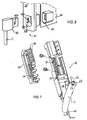
- the Figures 5 to 7 show in more detail, seen from behind, a terminal 31 belonging to a terminal module 30, the term "terminal" means located at the downstream end (opposite the coupler) of the main group.
- the terminal module 30 makes it possible to transmit to the head module 24 a secondary (or downstream) group 10B of modules associated with another zone MB of the island, or to a sub-island, the signals and preferably the voltage. higher of the link SB, without this group does not require the presence of a new coupler 20.
- a secondary group 10B is represented on the figure 1 .
- a power supply module 21, input and / or output modules 22 and a terminal module 40 which ensures the desired termination of the bus lines, for example a resistive looping.
- the modules of the group 10A those 24,21,22 and 40 of the group 10B are mounted on bases 11 ensuring the continuity of the links SB and PB.
- a module 40 of the type indicated for the group 10B is mounted at the end of the main group 10A.
- the link connection SB between groups 10A and 10B uses a cable C immunized to disturbances.
- the cable C is connected at one end to the link SB of the group 10A in its terminal module 30 (connector 41 indicated figure 1 ) and at a second end to the group 10B own SB link in its head module 24.
- the cable C is for example of the IEEE 1394 type and, as can be seen figure 7 , comprises a wire C1 conveying the highest voltage V1 of the link SB, a C2 voltage return wire 0V, and two pairs C3, C4 shielded and independent formed of twisted son to carry the bus signals.
- the head module 24 comprises means 24a, similar to the means 23a of the module 23, adapted to convert the "strong" voltage V1 (24V), transmitted via the cable C, "low” voltage V2 (5V). As a result, the SB link of the group 10B has a “low” voltage V2 level guaranteed.
- the terminal module 30 also makes it possible to supply, with the voltages of the link PB, automation components 15, sensors or actuators, which are not managed by the link SB. It thus has a terminal block 31 with terminals 32 for connecting the conductors 33 to the members 15; the terminals 32 are themselves connected by internal conductors 34 combed in a support 35 to connection pins 36 which cooperate with a not shown connector of the printed circuit of the module 30.
- the terminal block is pivotally mounted on the housing of the module 30 and is compartmentalized at its lower part by a pivoting flap 37 which separates a front passage 38 (rear on the Figures 5 to 7 ) a rear seat 39 (front on Figures 5 to 7 ).
- the flap 37 makes it possible to pass in the passage 38 the conductors 33 connected to the terminals 32; when it is closed ( figures 5 and 7 ), the flap 37 makes it possible to leave a substantial space for the passage of the cable C.
- the cable C occupies a rather large volume, because of its constitution and properties of immunity to disturbances.
- the arrangement indicated terminal module makes it easy to provide a signal link with the connector 41 at the top of the module and a power link with the terminals 32 located at the bottom of the module, thanks to the subdivision of the lower end of the terminal block 31 .
- connection 41 of the connecting cable C has a female portion 42 provided with shapes 42a intended to cooperate with respective shapes 30a provided in an engagement channel 30b of the terminal module 30.
- the female part 42 of the connector can connect to the male portion 43 of the soldered connector to an electronic circuit board 44 by eliminating the risk of damaging the welds by vibrations between connection 41 and module 30. Guiding shapes 30c of the female part 42 are also provided in FIG. the channel 30b.
Landscapes
- Engineering & Computer Science (AREA)
- Automation & Control Theory (AREA)
- Microelectronics & Electronic Packaging (AREA)
- Programmable Controllers (AREA)
- Replacing, Conveying, And Pick-Finding For Filamentary Materials (AREA)
- Processing Of Terminals (AREA)
- Manufacturing Of Electrical Connectors (AREA)
- Power Sources (AREA)
Description
- La présente invention concerne un dispositif d'automatisation modulaire associé à un îlot d'automatisme, ce dispositif comprenant un groupe principal de modules juxtaposés sur un support, lequel groupe présente un organe de commande, tel qu'un coupleur de bus, un module d'alimentation apte à distribuer au moins une tension d'alimentation nécessaire aux organes d'automatisme de l'îlot, et plusieurs modules fonctionnels d'entrée et/ou de sortie auxquels se raccordent les organes d'automatisme.
- Le coupleur de bus est apte à acheminer des signaux de contrôle-commande entre un bus externe, notamment un bus de terrain, de liaison avec un système de commande et/ou de surveillance tel qu'un automate programmable. Le dispositif d'automatisation doit d'autre part assurer l'alimentation des circuits électroniques des divers modules sous une tension de bas niveau, typiquement 5V ou 24Vdc. II doit aussi fournir au moins une tension d'alimentation, désignée par la suite comme tension "applicative", pour des organes applicatifs d'automatisme, tels que des capteurs et actionneurs, cette tension étant typiquement de 24V ou 48Vdc (courant continu) ou de 110V ou 250Vac (courant alternatif). Les modules fonctionnels d'entrée-sortie communiquent les signaux et tensions applicatives aux capteurs et actionneurs.
- II existe, entre les modules, une liaison dite de signaux, pour acheminer les signaux de contrôle et au moins une tension de fonctionnement des modules, et une liaison dite d'alimentation, acheminant les tensions d'alimentation applicatives, nécessaires au fonctionnement des organes applicatifs. Ces liaisons constituent des bus internes réalisés soit en fond de bac ou dans un socle, soit au moyen d'embases individuelles interconnectées latéralement.
- De tels dispositifs sont bien connus, notamment d'après les documents
EP 661 915 EP 677 986 EP 1 022 809 . L'agencement modulaire des dispositifs connus permet d'étendre facilement leur capacité d'action par l'adjonction de modules. Dans une installation automatisée ou une machine, il s'avère cependant parfois nécessaire de distinguer diverses zones, différenciées par exemple par leur fonction ou leur relatif éloignement, en affectant à une zone principale un groupe principal de modules et à une zone secondaire au moins un groupe secondaire de modules.
Mais il faut alors prévoir pour chaque groupe secondaire un coupleur de bus, ce qui est coûteux. - L'invention a notamment pour but d'adapter un dispositif d'automatisation du type décrit pour éviter la présence d'un coupleur de bus dans un groupe secondaire de modules relié au groupe principal.
- Selon l'invention qui est bien définie dans la revendication 1, le dispositif comprend au moins un groupe secondaire de modules associé à une zone secondaire de l'îlot et présentant un module de tête, ainsi qu'une première et une deuxième liaison prolongeant celles du groupe principal,
- un câble de liaison, associé à la première liaison et apte à acheminer les signaux de contrôle-commande et une tension d'alimentation des modules, est connecté à un module terminal du groupe principal et au module de tête du groupe secondaire, lequel module de tête du groupe secondaire possède des moyens aptes à acheminer de façon immune vers le (ou du) groupe secondaire les signaux de contrôle-commande et à acheminer vers le groupe secondaire une tension d'alimentation des modules.
- Le groupe principal de modules comprend de préférence au moins un module d'alimentation des circuits électroniques des modules situés en aval, ce module possédant des moyens convertisseurs de tension aptes à rétablir à son niveau nominal une tension d'alimentation basse de la première liaison à partir d'une tension d'alimentation haute de cette même liaison. Le module de tête du groupe secondaire peut également posséder de tels moyens convertisseurs de tension.
- Un module d'alimentation connecté à une source de tension externe et apte à distribuer au moins une tension d'alimentation nécessaire aux organes d'automatisme peut être disposé en adjacence au module de tête du groupe secondaire.
- Le module terminal du groupe principal permet avantageusement d'appliquer, au moyen d'au moins un conducteur d'alimentation distinct du câble de liaison, les tensions de la deuxième liaison de bus à des organes d'automatisme non gérés par la première liaison de bus. A cet effet, le module terminal peut présenter un bornier prévu pour connecter les conducteurs d'alimentation de l'organe d'application et cloisonné, notamment au moyen d'un volet mobile, pour séparer le câble de liaison des conducteurs d'alimentation.
- La description va être faite ci-après d'un mode de réalisation non limitatif de l'invention, en regard des dessins annexés.
- La
figure 1 représente schématiquement de face un dispositif d'automatisation conforme à l'invention. - La
figure 2 montre un détail de la liaison de signaux assurée entre les modules du dispositif. - La
figure 3 montre un détail de conversion de tension propre à la liaison de signaux. - La
figure 4 représente en perspective un module d'entrée-sortie du dispositif. - La
figure 5 montre en perspective arrière un bornier d'un module terminal du dispositif. - La
figure 6 illustre un détail de ce module. - La
figure 7 est une perspective éclatée du bornier de lafigure 5 . - La
figure 8 illustre un détail de connexion du câble de liaison. - Le dispositif illustré sur les figures comprend un groupe principal 10A de modules électroniques destinés à être emboîtés et encliquetés dans des embases individuelles 11 (voir
figure 2 ) elles-mêmes encliquetables en adjacence par tous moyens usuels sur un support, par exemple un profilé chapeau 12. Le groupe de modules 10A est associé à une zone MA d'un îlot d'automatisation, par exemple une machine ou partie de machine, et régit le flux de données vers l'îlot ou en provenance de l'îlot. De plus, par le groupe de modules 10A transite l'alimentation des organes d'automatisme - capteurs 13 ou actionneurs 14 - associés à la zone MA. - A cet effet, le groupe de modules comprend une liaison SB affectée aux signaux et à l'alimentation des circuits des modules et une liaison PB affectée à l'alimentation des organes d'automatisme pour leur transmettre les tensions requises par l'îlot. Les embases 11 sont interconnectées latéralement par des contacts coopérants SBC et PBC de manière à assurer la continuité de ces liaisons. Les liaisons SB,PB sont situées en hauteur à des niveaux différents, mais en profondeur au même niveau (voir
figure 4 ). - Le groupe 10A comprend en tête un organe de commande constitué ici par un coupleur 20 auquel se raccorde un bus externe de terrain B - par exemple de type CA-NOpen, DeviceNet, Ethernet, Fipl/O, Modbus, Profibus ou autre - relié à un automate programmable ou autre organe de contrôle / commande. En variante, l'organe de commande peut être une unité centrale.
- Le groupe 10A comporte aussi au moins un module d'alimentation 21 apte à fournir aux capteurs 13 et actionneurs 14, à partir de tensions externes Uin et/ou Uout, les tensions d'alimentation qui leur sont nécessaires, ainsi que des modules 22 d'entrée/sortie de diverses tailles reliés aux organes 13,14 et un module terminal 30. Les modules 22 sont munis de circuits imprimés et connecteurs appropriés et il est prévu un module 23 garantissant le niveau des tensions d'alimentation des circuits électroniques des modules 22. Ce module permet, lorsqu'une chute excessive de tension risque de se manifester pour l'une des tensions de la liaison SB, de rétablir la tension considérée à son niveau nominal à partir de la plus élevée des tensions de la liaison SB.
- La
figure 2 montre un exemple de composition de la liaison bas niveau SB : une ligne de tension "haute" V1 (24V), une ligne 0V, une ligne de tension "basse" V2 (5V), et des lignes de signaux dépendant du type de bus adopté ; ici, le bus interne étant de type CAN, il s'agit de lignes CANH et CANL et d'une ligne d'adressage ADDR. Le coupleur 20 comprend des moyens d'interfaçage et de liaison 20a qui couplent les lignes de la liaison SB à celles du bus B. - Le module d'alimentation de puissance 21 comprend des moyens 21 a de liaison et conversion des tensions de source externe Uin (tension des capteurs),Uout (tension des actionneurs) avec les tensions souhaitées sur la liaison PB : par exemple 24 ou 48V do pour les capteurs et 24Vdc, 48Vdc, 110 Vac ou 250Vac pour les actionneurs. Les tensions Uin,Uout disponibles sont sécurisées ou non sécurisées en fonction de l'îlot d'automatisme considéré. Le module d'alimentation 21 assure la mise à la terre du groupe de modules.
- La tension V1 est moins affectée par la longueur du chemin de transmisssion que la tension V2 ; il est donc intéressant d'utiliser la tension V1 (24V) pour régénérer la tension V2 (5V). Ainsi, comme indiqué
figure 3 , le module 23 comporte un circuit convertisseur 23a qui convertit la tension 24Vdc en tension 5Vdc pour assurer que les modules 22 situés en aval du module 23 seront alimentés convenablement en tension 5V. - Comme indiqué
figure 4 , un module 22 d'entrée/sortie comprend un boîtier 22a encliqueté de manière amovible sur une embase 11. A l'avant du boîtier 22a peut être fixé un bornier 22b de raccordement externe aux organes d'automatisme 13,14 à surveiller ou commander, des connexions 22c étant prévues à l'avant du boîtier pour coopérer avec des connexions complémentaires du bornier 22b. Des éléments de connexion ou contacts 22d,22e sont disposés vers l'arrière du boîtier pour se connecter à des pièces de connexion appropriées elles-mêmes reliées à la liaison bas niveau SB et respectivement à la liaison de puissance PB. II convient de noter que chaque module 22 peut être enlevé du groupe en fonctionnement sans altérer la continuité des bus, ni le fonctionnement des modules situés en aval (réalisation "hotswap"). - Les
figures 5 à 7 montrent plus en détail, vu de derrière, un bornier 31 appartenant à un module terminal 30, le terme "terminal" signifiant situé à l'extrémité aval (à l'opposé du coupleur) du groupe principal. Le module terminal 30 permet de transmettre au module de tête 24 d'un groupe secondaire (ou aval) 10B de modules associé à une autre zone MB de l'îlot, ou à un sous-îlot, les signaux et de préférence la tension la plus élevée de la liaison SB, sans que ce groupe ne nécessite la présence d'un nouveau coupleur 20. Un tel groupe secondaire 10B est représenté sur lafigure 1 . II comprend successivement, outre le module de tête 24, un module d'alimentation de puissance 21, des modules 22 d'entrée et/ou de sortie et un module terminal 40 qui assure la terminaison voulue des lignes de bus, par exemple un bouclage résistif. Comme pour les modules du groupe 10A, ceux 24,21,22 et 40 du groupe 10B sont montés sur des embases 11 assurant la continuité des liaisons SB et PB. En l'absence de groupe secondaire 10B, on monte à l'extrémité du groupe principal 10A un module 40 du type indiqué pour le groupe 10B. - La connexion de liaison SB entre les groupes 10A et 10B utilise un câble C immunisé aux perturbations. Le câble C est connecté à une première extrémité à la liaison SB du groupe 10A dans son module terminal 30 (connecteur 41 indiqué
figure 1 ) et à une deuxième extrémité à la liaison SB propre au groupe 10B dans son module de tête 24. Le câble C est par exemple du type IEEE 1394 et, comme on le voitfigure 7 , comporte un fil C1 acheminant la tension V1 la plus élevée de la liaison SB, un fil C2 de retour de tension 0V, et deux paires C3,C4 blindées et indépendantes formées de fils torsadés pour acheminer les signaux de bus. Le module de tête 24 comporte des moyens 24a, analogues aux moyens 23a du module 23, propres à convertir la "forte" tension V1 (24V), transmise via le câble C, en "faible" tension V2 (5V). II en résulte que la liaison SB du groupe 10B dispose d'une "faible" tension V2 de niveau garanti. - Le module terminal 30 permet aussi d'alimenter avec les tensions de la liaison PB des organes d'automatisme 15, capteurs ou actionneurs, non gérés par la liaison SB. II présente ainsi un bornier 31 doté de bornes 32 pour connecter les conducteurs 33 aux organes 15 ; les bornes 32 sont elles-mêmes reliées par des conducteurs internes 34 montés en peigne dans un support 35 à des broches de connexion 36 qui coopèrent avec un connecteur non représenté du circuit imprimé du module 30. Le bornier est monté de manière pivotante sur le boîtier du module 30 et il est compartimenté à sa partie basse par un volet pivotant 37 qui sépare un passage avant 38 (arrière sur les
figures 5 à 7 ) d'un logement arrière 39 (avant sur lesfigures 5 à 7 ). - En position ouverte (
figure 6 ), le volet 37 permet de faire passer dans le passage 38 les conducteurs 33 connectés aux bornes 32 ; quand il est refermé (figures 5 et7 ), le volet 37 permet de laisser un espace substantiel pour le passage du câble C. II convient de remarquer que le câble C occupe un volume assez important, du fait de sa constitution et de ses propriétés d'immunité aux perturbations. L'agencement indiqué du module terminal permet d'assurer aisément une liaison de signal avec le connecteur 41 situé en haut du module et une liaison de puissance avec les bornes 32 situées à la partie basse du module, grâce au compartimentage de l'extrémité inférieure du bornier 31. - Comme on le voit
figure 8 , le raccord 41 du câble de liaison C présente une partie femelle 42 doté de formes 42a destinées à coopérer avec des formes respectives 30a prévues dans un canal d'engagement 30b du module terminal 30. De la sorte, la partie femelle 42 du connecteur peut se connecter à la partie mâle 43 du connecteur soudée à une carte à circuit électronique 44 en éliminant le risque d'endommagement des soudures par les vibrations entre raccord 41 et module 30. Des formes 30c de guidage de la partie femelle 42 sont aussi prévues dans le canal 30b.
Claims (8)
- Dispositif d'automatisation comprenant un ensemble modulaire associé à un îlot d'automatisme et comprenant un groupe principal (10A) de modules juxtaposés sur un support associé à une zone principale de l'ilôt, le groupe principal comportant un organe de commande (20) apte à acheminer des signaux de contrôle-commande, un module d'alimentation (21) apte à distribuer au moins une tension d'alimentation (Un, Uout) pour des organes d'automatisme, plusieurs modules fonctionnels (22), avec, entre les modules, une première liaison (SB) qui achemine les signaux de contrôle et au moins une tension d'alimentation des modules et une deuxième liaison (PB) qui achemine les tensions d'alimentation des organes d'automatisme, et un module terminal (30),
caractérisé par le fait que :- le dispositif comprend au moins un groupe secondaire de modules (10B) associé à une zone secondaire de l'îlot et présentant un module de tête (24), ainsi qu'une première et une deuxième liaison (SB,PB) prolongeant celles du groupe principal (10A),- un câble de liaison (C) associé à la première liaison (SB) et apte à acheminer de façon immune les signaux de contrôle-commande et une tension d'alimentation (V1) des modules, le câble étant connecté au module terminal (30) du groupe principal et au module de tête (24) du groupe secondaire (10B). - Dispositif selon la revendication 1, caractérisé par le fait que le groupe principal (10A) comprend au moins un module d'alimentation (23) des circuits électroniques des modules situés en aval, ce module possédant des moyens (23a) convertisseurs de tension aptes à rétablir à son niveau nominal une tension d'alimentation basse (V2) de la première liaison (SB) à partir d'une tension d'alimentation haute (V1) de cette même liaison.
- Dispositif selon la revendication 1 ou 2, caractérisé par le fait que le module de tête (24) du groupe secondaire (10B) possède des moyens (24a) convertisseurs de tension aptes à rétablir à son niveau nominal une tension d'alimentation basse (V2) de la première liaison (SB) à partir d'une tension d'alimentation haute (V1) de cette même liaison.
- Dispositif selon la revendication 1, caractérisé par le fait qu'un module d'alimentation (21) connecté à une source de tension externe et apte à distribuer au moins une tension d'alimentation (Uin, Uout) pour des organes d'automatisme est disposé adjacent au module de tête (24) du groupe secondaire (10B).
- Dispositif selon la revendication 1, caractérisé par le fait que le module terminal (30) du groupe principal (10A) permet d'appliquer, au moyen d'au moins un conducteur d'alimentation (33) distinct du câble (C), les tensions de la deuxième liaison de bus (PB) à des organes d'automatisme (15) non gérés par la première liaison de bus (SB).
- Dispositif selon la revendication 5, caractérisé par le fait que le module terminal (30) du groupe principal (10A) présente un bornier (31) pourvu de bornes (32) pour les conducteurs d'alimentation (33) des organes d'automatisme et cloisonné pour séparer le câble de liaison (C) des conducteurs (33).
- Dispositif selon la revendication 6, caractérisé par le fait que le bornier (31) est cloisonné au moyen d'un volet mobile (36) qui ménage d'un côté un espace pour le passage du câble de liaison (C) et de l'autre côté un espace pour les conducteurs d'alimentation (33).
- Dispositif selon la revendication 1, caractérisé par le fait que le câble de liaison (C) est connecté au module terminal (30) par un connecteur (41) présentant une partie femelle (42) et une partie mâle (43) soudée à un circuit imprimé (44), le module présentant un canal (30b) d'engagement de la partie femelle, la partie femelle et le canal étant pourvus de formes respectives (42a,30a) évitant la transmission des vibrations du connecteur au circuit imprimé.
Applications Claiming Priority (2)
| Application Number | Priority Date | Filing Date | Title |
|---|---|---|---|
| FR0204833 | 2002-04-15 | ||
| FR0204833A FR2838600B1 (fr) | 2002-04-15 | 2002-04-15 | Dispositif d'automatisation modulaire |
Publications (2)
| Publication Number | Publication Date |
|---|---|
| EP1355523A1 EP1355523A1 (fr) | 2003-10-22 |
| EP1355523B1 true EP1355523B1 (fr) | 2010-04-21 |
Family
ID=28459915
Family Applications (1)
| Application Number | Title | Priority Date | Filing Date |
|---|---|---|---|
| EP03100955A Revoked EP1355523B1 (fr) | 2002-04-15 | 2003-04-09 | Dispositif d'automatisation modulaire. |
Country Status (5)
| Country | Link |
|---|---|
| US (1) | US7190093B2 (fr) |
| EP (1) | EP1355523B1 (fr) |
| AT (1) | ATE465623T1 (fr) |
| DE (1) | DE60332186D1 (fr) |
| FR (1) | FR2838600B1 (fr) |
Families Citing this family (10)
| Publication number | Priority date | Publication date | Assignee | Title |
|---|---|---|---|---|
| US7024261B1 (en) * | 2001-12-17 | 2006-04-04 | Tanton Chris D | Modular automation apparatus |
| US7440262B2 (en) * | 2006-12-06 | 2008-10-21 | Adc Telecommunications, Inc. | Modular power distribution system and methods |
| EP1983812B1 (fr) * | 2007-04-16 | 2013-11-20 | Abb Research Ltd. | Dispositif électronique intelligent pour une sous-station ou des systèmes de distribution automatisés |
| CN102210078B (zh) * | 2008-10-09 | 2014-10-29 | Adc电信公司 | 电力切换装置 |
| CN102640388B (zh) * | 2009-12-08 | 2016-03-09 | Abb技术有限公司 | I/o模块 |
| US8400760B2 (en) * | 2009-12-28 | 2013-03-19 | Transtector Systems, Inc. | Power distribution device |
| US9533387B2 (en) | 2012-07-12 | 2017-01-03 | Specialty Technologies L.L.C. | Apparatus and control for modular manufacturing system |
| FR3000319B1 (fr) * | 2012-12-21 | 2019-03-29 | Schneider Electric Industries Sas | Module entree a connexion autoportee |
| DE102013213724A1 (de) * | 2013-07-12 | 2015-01-15 | Siemens Aktiengesellschaft | Busanschlussvorrichtung |
| GB2547946B (en) * | 2016-03-04 | 2020-05-20 | Ge Aviat Systems Ltd | Method and apparatus for modular power distribution |
Family Cites Families (14)
| Publication number | Priority date | Publication date | Assignee | Title |
|---|---|---|---|---|
| JPS6118003A (ja) * | 1984-07-04 | 1986-01-25 | Hitachi Ltd | 制御装置 |
| US5117122A (en) * | 1989-01-19 | 1992-05-26 | Hogarth Peter T | Integrated outlet for communication and electrical power transmissions with noise reducing characteristics |
| JP3250264B2 (ja) * | 1992-07-08 | 2002-01-28 | 株式会社村田製作所 | 終端抵抗回路 |
| DE4223193A1 (de) * | 1992-07-15 | 1994-01-20 | Abb Patent Gmbh | Programmierbare Steuerung mit Anschlußeinheiten zur Verbindung mit analogen und/oder digitalen Peripheriegeräten |
| US7176589B2 (en) * | 1995-09-22 | 2007-02-13 | Input/Output, Inc. | Electrical power distribution and communication system for an underwater cable |
| JP3090071B2 (ja) * | 1996-11-29 | 2000-09-18 | オムロン株式会社 | 制御装置 |
| NL1004934C2 (nl) * | 1997-01-06 | 1998-07-16 | Ten Holter Consultancy | Systeem voor het op centraal niveau en op afstand, met behulp van een computer of lokaal d.m.v. signaalmediums, individueel schakelen van elektriciteitsverbruikers in een gebouw, waarbij alle stuur-, voedings- en schakelapparatuur op een of meerdere (dagelijks) bereikbare centrale lokaties geplaatst is. Een en ander door gebruik te maken van de ontwikkelde gestandaardiseerde Differentiated Electric Power Switch (öDEPSö)-modules met bijbehorende systeemopzet. |
| DE19716137C1 (de) * | 1997-04-17 | 1998-10-22 | Siemens Ag | Modul zum Anschluß von Aktoren und/oder Sensoren |
| WO2000014798A1 (fr) * | 1998-09-02 | 2000-03-16 | Ibiden Co., Ltd. | Module de piece electronique monte sur une carte de connexion |
| US6487091B2 (en) * | 1999-09-28 | 2002-11-26 | Rockwell Automation Technologies, Inc. | Method and apparatus for supplying data and power to panel-supported components |
| AU2002235531A1 (en) * | 2001-02-06 | 2002-08-19 | Byrne, Norman, R. | Electrical floor access module system |
| GB0105856D0 (en) * | 2001-03-09 | 2001-04-25 | Alpha Thames Ltd | Power connection to and/or control of wellhead trees |
| US6937461B1 (en) * | 2001-11-28 | 2005-08-30 | Donahue, Iv William F. | Modular power distribution unit, module for the power distribution unit, and method of using the same |
| US7024261B1 (en) * | 2001-12-17 | 2006-04-04 | Tanton Chris D | Modular automation apparatus |
-
2002
- 2002-04-15 FR FR0204833A patent/FR2838600B1/fr not_active Expired - Lifetime
-
2003
- 2003-04-09 AT AT03100955T patent/ATE465623T1/de not_active IP Right Cessation
- 2003-04-09 EP EP03100955A patent/EP1355523B1/fr not_active Revoked
- 2003-04-09 DE DE60332186T patent/DE60332186D1/de not_active Expired - Lifetime
- 2003-04-14 US US10/412,236 patent/US7190093B2/en not_active Expired - Fee Related
Also Published As
| Publication number | Publication date |
|---|---|
| US7190093B2 (en) | 2007-03-13 |
| DE60332186D1 (de) | 2010-06-02 |
| ATE465623T1 (de) | 2010-05-15 |
| EP1355523A1 (fr) | 2003-10-22 |
| US20030193784A1 (en) | 2003-10-16 |
| FR2838600A1 (fr) | 2003-10-17 |
| FR2838600B1 (fr) | 2004-05-28 |
Similar Documents
| Publication | Publication Date | Title |
|---|---|---|
| EP1355523B1 (fr) | Dispositif d'automatisation modulaire. | |
| US20030194914A1 (en) | Modular plug connector | |
| DE69938111T2 (de) | Lokales netzwerk von seriellen intelligenten zellen | |
| US11936497B2 (en) | Module unit for connecting a data bus subscriber | |
| US5535036A (en) | Input/output module providing mixed optical and electrical signal connectivity in data communications equipment | |
| JPS62114021A (ja) | バツクプレイン・バスを有するバツクプレイン | |
| EP4042247B1 (fr) | Appareil d'entrée/sortie et procédés de surveillance et/ou de contrôle d'environnements dynamiques | |
| US7508690B2 (en) | Monitoring and control device and bridge module therefor | |
| EP0566481B1 (fr) | Structure d'accueil pour adaptateurs de terminaux | |
| CN107966922A (zh) | 模块化子机架中的单通道输入/输出 | |
| EP2009808A1 (fr) | Communication par courant porteur pour les tableaux centralisés de commande | |
| US20100271794A1 (en) | Hardware module and backplane board for an ied | |
| EP3345270A1 (fr) | Systeme de distribution de courant electrique pour vehicule | |
| US11848525B2 (en) | Single-pair ethernet device, single-pair ethernet system and method for installing a single-pair ethernet system | |
| FR3014285A1 (fr) | Module a circuits relais electrique et centre electrique pour vehicule comprenant un tel module a circuits relais electrique. | |
| EP3309806A1 (fr) | Commutateur intelligent pour application automobile | |
| EP2079194B1 (fr) | Système de contrôle d'entraînement dédié à double anneau pour des entraînements moyenne tension à fréquence variable | |
| FR2513477A1 (fr) | Equipement electrique du type comprenant plusieurs cartes de circuit imprime raccordees a un plan de connexions | |
| JP4937889B2 (ja) | 車載用ゲートウェイ装置 | |
| FR2590101A1 (fr) | Repartiteur electronique et application a la commutation de lignes telephoniques | |
| EP0720331A1 (fr) | Agencement de chaînage entre modules intermédiaires, notamment de type répéteur et installation ainsi équipée | |
| FR2800221A1 (fr) | Dispositif et boitier pour raccordement a un reseau local | |
| EP0061963A1 (fr) | Dispositif de contrôle de trafic par signaux lumineux | |
| CN1112745C (zh) | 给插接组件编码的装置及连接外部导线的装置 | |
| EP3621171B1 (fr) | Installation électrique à redéploiement rapide |
Legal Events
| Date | Code | Title | Description |
|---|---|---|---|
| PUAI | Public reference made under article 153(3) epc to a published international application that has entered the european phase |
Free format text: ORIGINAL CODE: 0009012 |
|
| AK | Designated contracting states |
Kind code of ref document: A1 Designated state(s): AT BE BG CH CY CZ DE DK EE ES FI FR GB GR HU IE IT LI LU MC NL PT RO SE SI SK TR |
|
| AX | Request for extension of the european patent |
Extension state: AL LT LV MK |
|
| RIN1 | Information on inventor provided before grant (corrected) |
Inventor name: RIX, PHILIPPE Inventor name: GIRARD, MICHEL Inventor name: BET, ROBERT |
|
| 17P | Request for examination filed |
Effective date: 20031105 |
|
| AKX | Designation fees paid |
Designated state(s): AT BE BG CH CY CZ DE DK EE ES FI FR GB GR HU IE IT LI LU MC NL PT RO SE SI SK TR |
|
| GRAP | Despatch of communication of intention to grant a patent |
Free format text: ORIGINAL CODE: EPIDOSNIGR1 |
|
| GRAS | Grant fee paid |
Free format text: ORIGINAL CODE: EPIDOSNIGR3 |
|
| GRAA | (expected) grant |
Free format text: ORIGINAL CODE: 0009210 |
|
| AK | Designated contracting states |
Kind code of ref document: B1 Designated state(s): AT BE BG CH CY CZ DE DK EE ES FI FR GB GR HU IE IT LI LU MC NL PT RO SE SI SK TR |
|
| REG | Reference to a national code |
Ref country code: GB Ref legal event code: FG4D Free format text: NOT ENGLISH |
|
| REG | Reference to a national code |
Ref country code: CH Ref legal event code: EP |
|
| REG | Reference to a national code |
Ref country code: IE Ref legal event code: FG4D Free format text: LANGUAGE OF EP DOCUMENT: FRENCH |
|
| REF | Corresponds to: |
Ref document number: 60332186 Country of ref document: DE Date of ref document: 20100602 Kind code of ref document: P |
|
| REG | Reference to a national code |
Ref country code: NL Ref legal event code: VDEP Effective date: 20100421 |
|
| PG25 | Lapsed in a contracting state [announced via postgrant information from national office to epo] |
Ref country code: NL Free format text: LAPSE BECAUSE OF FAILURE TO SUBMIT A TRANSLATION OF THE DESCRIPTION OR TO PAY THE FEE WITHIN THE PRESCRIBED TIME-LIMIT Effective date: 20100421 Ref country code: SE Free format text: LAPSE BECAUSE OF FAILURE TO SUBMIT A TRANSLATION OF THE DESCRIPTION OR TO PAY THE FEE WITHIN THE PRESCRIBED TIME-LIMIT Effective date: 20100421 Ref country code: ES Free format text: LAPSE BECAUSE OF FAILURE TO SUBMIT A TRANSLATION OF THE DESCRIPTION OR TO PAY THE FEE WITHIN THE PRESCRIBED TIME-LIMIT Effective date: 20100801 |
|
| REG | Reference to a national code |
Ref country code: IE Ref legal event code: FD4D |
|
| PG25 | Lapsed in a contracting state [announced via postgrant information from national office to epo] |
Ref country code: SI Free format text: LAPSE BECAUSE OF FAILURE TO SUBMIT A TRANSLATION OF THE DESCRIPTION OR TO PAY THE FEE WITHIN THE PRESCRIBED TIME-LIMIT Effective date: 20100421 Ref country code: AT Free format text: LAPSE BECAUSE OF FAILURE TO SUBMIT A TRANSLATION OF THE DESCRIPTION OR TO PAY THE FEE WITHIN THE PRESCRIBED TIME-LIMIT Effective date: 20100421 Ref country code: FI Free format text: LAPSE BECAUSE OF FAILURE TO SUBMIT A TRANSLATION OF THE DESCRIPTION OR TO PAY THE FEE WITHIN THE PRESCRIBED TIME-LIMIT Effective date: 20100421 |
|
| PG25 | Lapsed in a contracting state [announced via postgrant information from national office to epo] |
Ref country code: GR Free format text: LAPSE BECAUSE OF FAILURE TO SUBMIT A TRANSLATION OF THE DESCRIPTION OR TO PAY THE FEE WITHIN THE PRESCRIBED TIME-LIMIT Effective date: 20100722 Ref country code: CY Free format text: LAPSE BECAUSE OF FAILURE TO SUBMIT A TRANSLATION OF THE DESCRIPTION OR TO PAY THE FEE WITHIN THE PRESCRIBED TIME-LIMIT Effective date: 20100421 |
|
| PLBI | Opposition filed |
Free format text: ORIGINAL CODE: 0009260 |
|
| PG25 | Lapsed in a contracting state [announced via postgrant information from national office to epo] |
Ref country code: IE Free format text: LAPSE BECAUSE OF FAILURE TO SUBMIT A TRANSLATION OF THE DESCRIPTION OR TO PAY THE FEE WITHIN THE PRESCRIBED TIME-LIMIT Effective date: 20100421 Ref country code: PT Free format text: LAPSE BECAUSE OF FAILURE TO SUBMIT A TRANSLATION OF THE DESCRIPTION OR TO PAY THE FEE WITHIN THE PRESCRIBED TIME-LIMIT Effective date: 20100823 Ref country code: EE Free format text: LAPSE BECAUSE OF FAILURE TO SUBMIT A TRANSLATION OF THE DESCRIPTION OR TO PAY THE FEE WITHIN THE PRESCRIBED TIME-LIMIT Effective date: 20100421 Ref country code: DK Free format text: LAPSE BECAUSE OF FAILURE TO SUBMIT A TRANSLATION OF THE DESCRIPTION OR TO PAY THE FEE WITHIN THE PRESCRIBED TIME-LIMIT Effective date: 20100421 |
|
| PG25 | Lapsed in a contracting state [announced via postgrant information from national office to epo] |
Ref country code: SK Free format text: LAPSE BECAUSE OF FAILURE TO SUBMIT A TRANSLATION OF THE DESCRIPTION OR TO PAY THE FEE WITHIN THE PRESCRIBED TIME-LIMIT Effective date: 20100421 Ref country code: RO Free format text: LAPSE BECAUSE OF FAILURE TO SUBMIT A TRANSLATION OF THE DESCRIPTION OR TO PAY THE FEE WITHIN THE PRESCRIBED TIME-LIMIT Effective date: 20100421 Ref country code: CZ Free format text: LAPSE BECAUSE OF FAILURE TO SUBMIT A TRANSLATION OF THE DESCRIPTION OR TO PAY THE FEE WITHIN THE PRESCRIBED TIME-LIMIT Effective date: 20100421 |
|
| 26 | Opposition filed |
Opponent name: WAGO KONTAKTTECHNIK GMBH & CO. KG Effective date: 20110121 |
|
| PLAX | Notice of opposition and request to file observation + time limit sent |
Free format text: ORIGINAL CODE: EPIDOSNOBS2 |
|
| PG25 | Lapsed in a contracting state [announced via postgrant information from national office to epo] |
Ref country code: IT Free format text: LAPSE BECAUSE OF FAILURE TO SUBMIT A TRANSLATION OF THE DESCRIPTION OR TO PAY THE FEE WITHIN THE PRESCRIBED TIME-LIMIT Effective date: 20100421 |
|
| PLBB | Reply of patent proprietor to notice(s) of opposition received |
Free format text: ORIGINAL CODE: EPIDOSNOBS3 |
|
| BERE | Be: lapsed |
Owner name: SCHNEIDER AUTOMATION INC. Effective date: 20110430 |
|
| PG25 | Lapsed in a contracting state [announced via postgrant information from national office to epo] |
Ref country code: MC Free format text: LAPSE BECAUSE OF NON-PAYMENT OF DUE FEES Effective date: 20110430 |
|
| REG | Reference to a national code |
Ref country code: CH Ref legal event code: PL |
|
| PG25 | Lapsed in a contracting state [announced via postgrant information from national office to epo] |
Ref country code: CH Free format text: LAPSE BECAUSE OF NON-PAYMENT OF DUE FEES Effective date: 20110430 Ref country code: LI Free format text: LAPSE BECAUSE OF NON-PAYMENT OF DUE FEES Effective date: 20110430 Ref country code: BE Free format text: LAPSE BECAUSE OF NON-PAYMENT OF DUE FEES Effective date: 20110430 |
|
| PGFP | Annual fee paid to national office [announced via postgrant information from national office to epo] |
Ref country code: FR Payment date: 20120322 Year of fee payment: 10 |
|
| PGFP | Annual fee paid to national office [announced via postgrant information from national office to epo] |
Ref country code: DE Payment date: 20120303 Year of fee payment: 10 |
|
| PGFP | Annual fee paid to national office [announced via postgrant information from national office to epo] |
Ref country code: GB Payment date: 20120423 Year of fee payment: 10 |
|
| RDAF | Communication despatched that patent is revoked |
Free format text: ORIGINAL CODE: EPIDOSNREV1 |
|
| REG | Reference to a national code |
Ref country code: DE Ref legal event code: R064 Ref document number: 60332186 Country of ref document: DE Ref country code: DE Ref legal event code: R103 Ref document number: 60332186 Country of ref document: DE |
|
| RDAG | Patent revoked |
Free format text: ORIGINAL CODE: 0009271 |
|
| STAA | Information on the status of an ep patent application or granted ep patent |
Free format text: STATUS: PATENT REVOKED |
|
| 27W | Patent revoked |
Effective date: 20121210 |
|
| GBPR | Gb: patent revoked under art. 102 of the ep convention designating the uk as contracting state |
Effective date: 20121210 |
|
| REG | Reference to a national code |
Ref country code: DE Ref legal event code: R107 Ref document number: 60332186 Country of ref document: DE Effective date: 20130926 |
|
| PG25 | Lapsed in a contracting state [announced via postgrant information from national office to epo] |
Ref country code: BG Free format text: LAPSE BECAUSE OF FAILURE TO SUBMIT A TRANSLATION OF THE DESCRIPTION OR TO PAY THE FEE WITHIN THE PRESCRIBED TIME-LIMIT Effective date: 20100721 |
|
| PG25 | Lapsed in a contracting state [announced via postgrant information from national office to epo] |
Ref country code: HU Free format text: LAPSE BECAUSE OF FAILURE TO SUBMIT A TRANSLATION OF THE DESCRIPTION OR TO PAY THE FEE WITHIN THE PRESCRIBED TIME-LIMIT Effective date: 20100421 |
|
| PG25 | Lapsed in a contracting state [announced via postgrant information from national office to epo] |
Ref country code: LU Free format text: LAPSE BECAUSE OF NON-PAYMENT OF DUE FEES Effective date: 20100421 |
|
| PG25 | Lapsed in a contracting state [announced via postgrant information from national office to epo] |
Ref country code: TR Free format text: LAPSE BECAUSE OF FAILURE TO SUBMIT A TRANSLATION OF THE DESCRIPTION OR TO PAY THE FEE WITHIN THE PRESCRIBED TIME-LIMIT Effective date: 20100421 |