EP1356890A1 - Method of metal working/welding assisted by cryogen flow - Google Patents
Method of metal working/welding assisted by cryogen flow Download PDFInfo
- Publication number
- EP1356890A1 EP1356890A1 EP03252113A EP03252113A EP1356890A1 EP 1356890 A1 EP1356890 A1 EP 1356890A1 EP 03252113 A EP03252113 A EP 03252113A EP 03252113 A EP03252113 A EP 03252113A EP 1356890 A1 EP1356890 A1 EP 1356890A1
- Authority
- EP
- European Patent Office
- Prior art keywords
- cryogen
- particles
- molten metal
- ejected
- contact
- Prior art date
- Legal status (The legal status is an assumption and is not a legal conclusion. Google has not performed a legal analysis and makes no representation as to the accuracy of the status listed.)
- Granted
Links
Images


Classifications
-
- B—PERFORMING OPERATIONS; TRANSPORTING
- B23—MACHINE TOOLS; METAL-WORKING NOT OTHERWISE PROVIDED FOR
- B23K—SOLDERING OR UNSOLDERING; WELDING; CLADDING OR PLATING BY SOLDERING OR WELDING; CUTTING BY APPLYING HEAT LOCALLY, e.g. FLAME CUTTING; WORKING BY LASER BEAM
- B23K26/00—Working by laser beam, e.g. welding, cutting or boring
- B23K26/14—Working by laser beam, e.g. welding, cutting or boring using a fluid stream, e.g. a jet of gas, in conjunction with the laser beam; Nozzles therefor
- B23K26/144—Working by laser beam, e.g. welding, cutting or boring using a fluid stream, e.g. a jet of gas, in conjunction with the laser beam; Nozzles therefor the fluid stream containing particles, e.g. powder
-
- B—PERFORMING OPERATIONS; TRANSPORTING
- B23—MACHINE TOOLS; METAL-WORKING NOT OTHERWISE PROVIDED FOR
- B23K—SOLDERING OR UNSOLDERING; WELDING; CLADDING OR PLATING BY SOLDERING OR WELDING; CUTTING BY APPLYING HEAT LOCALLY, e.g. FLAME CUTTING; WORKING BY LASER BEAM
- B23K26/00—Working by laser beam, e.g. welding, cutting or boring
- B23K26/14—Working by laser beam, e.g. welding, cutting or boring using a fluid stream, e.g. a jet of gas, in conjunction with the laser beam; Nozzles therefor
- B23K26/1435—Working by laser beam, e.g. welding, cutting or boring using a fluid stream, e.g. a jet of gas, in conjunction with the laser beam; Nozzles therefor involving specially adapted flow-control means
- B23K26/1437—Working by laser beam, e.g. welding, cutting or boring using a fluid stream, e.g. a jet of gas, in conjunction with the laser beam; Nozzles therefor involving specially adapted flow-control means for flow-rate control
-
- B—PERFORMING OPERATIONS; TRANSPORTING
- B23—MACHINE TOOLS; METAL-WORKING NOT OTHERWISE PROVIDED FOR
- B23K—SOLDERING OR UNSOLDERING; WELDING; CLADDING OR PLATING BY SOLDERING OR WELDING; CUTTING BY APPLYING HEAT LOCALLY, e.g. FLAME CUTTING; WORKING BY LASER BEAM
- B23K26/00—Working by laser beam, e.g. welding, cutting or boring
- B23K26/14—Working by laser beam, e.g. welding, cutting or boring using a fluid stream, e.g. a jet of gas, in conjunction with the laser beam; Nozzles therefor
- B23K26/146—Working by laser beam, e.g. welding, cutting or boring using a fluid stream, e.g. a jet of gas, in conjunction with the laser beam; Nozzles therefor the fluid stream containing a liquid
-
- B—PERFORMING OPERATIONS; TRANSPORTING
- B23—MACHINE TOOLS; METAL-WORKING NOT OTHERWISE PROVIDED FOR
- B23K—SOLDERING OR UNSOLDERING; WELDING; CLADDING OR PLATING BY SOLDERING OR WELDING; CUTTING BY APPLYING HEAT LOCALLY, e.g. FLAME CUTTING; WORKING BY LASER BEAM
- B23K26/00—Working by laser beam, e.g. welding, cutting or boring
- B23K26/14—Working by laser beam, e.g. welding, cutting or boring using a fluid stream, e.g. a jet of gas, in conjunction with the laser beam; Nozzles therefor
- B23K26/1462—Nozzles; Features related to nozzles
- B23K26/1464—Supply to, or discharge from, nozzles of media, e.g. gas, powder, wire
- B23K26/147—Features outside the nozzle for feeding the fluid stream towards the workpiece
-
- B—PERFORMING OPERATIONS; TRANSPORTING
- B23—MACHINE TOOLS; METAL-WORKING NOT OTHERWISE PROVIDED FOR
- B23K—SOLDERING OR UNSOLDERING; WELDING; CLADDING OR PLATING BY SOLDERING OR WELDING; CUTTING BY APPLYING HEAT LOCALLY, e.g. FLAME CUTTING; WORKING BY LASER BEAM
- B23K26/00—Working by laser beam, e.g. welding, cutting or boring
- B23K26/16—Removal of by-products, e.g. particles or vapours produced during treatment of a workpiece
-
- B—PERFORMING OPERATIONS; TRANSPORTING
- B23—MACHINE TOOLS; METAL-WORKING NOT OTHERWISE PROVIDED FOR
- B23K—SOLDERING OR UNSOLDERING; WELDING; CLADDING OR PLATING BY SOLDERING OR WELDING; CUTTING BY APPLYING HEAT LOCALLY, e.g. FLAME CUTTING; WORKING BY LASER BEAM
- B23K26/00—Working by laser beam, e.g. welding, cutting or boring
- B23K26/20—Bonding
- B23K26/21—Bonding by welding
- B23K26/24—Seam welding
- B23K26/26—Seam welding of rectilinear seams
-
- B—PERFORMING OPERATIONS; TRANSPORTING
- B23—MACHINE TOOLS; METAL-WORKING NOT OTHERWISE PROVIDED FOR
- B23K—SOLDERING OR UNSOLDERING; WELDING; CLADDING OR PLATING BY SOLDERING OR WELDING; CUTTING BY APPLYING HEAT LOCALLY, e.g. FLAME CUTTING; WORKING BY LASER BEAM
- B23K26/00—Working by laser beam, e.g. welding, cutting or boring
- B23K26/36—Removing material
- B23K26/38—Removing material by boring or cutting
- B23K26/382—Removing material by boring or cutting by boring
-
- B—PERFORMING OPERATIONS; TRANSPORTING
- B23—MACHINE TOOLS; METAL-WORKING NOT OTHERWISE PROVIDED FOR
- B23K—SOLDERING OR UNSOLDERING; WELDING; CLADDING OR PLATING BY SOLDERING OR WELDING; CUTTING BY APPLYING HEAT LOCALLY, e.g. FLAME CUTTING; WORKING BY LASER BEAM
- B23K26/00—Working by laser beam, e.g. welding, cutting or boring
- B23K26/36—Removing material
- B23K26/40—Removing material taking account of the properties of the material involved
-
- B—PERFORMING OPERATIONS; TRANSPORTING
- B23—MACHINE TOOLS; METAL-WORKING NOT OTHERWISE PROVIDED FOR
- B23K—SOLDERING OR UNSOLDERING; WELDING; CLADDING OR PLATING BY SOLDERING OR WELDING; CUTTING BY APPLYING HEAT LOCALLY, e.g. FLAME CUTTING; WORKING BY LASER BEAM
- B23K9/00—Arc welding or cutting
- B23K9/16—Arc welding or cutting making use of shielding gas
-
- B—PERFORMING OPERATIONS; TRANSPORTING
- B23—MACHINE TOOLS; METAL-WORKING NOT OTHERWISE PROVIDED FOR
- B23K—SOLDERING OR UNSOLDERING; WELDING; CLADDING OR PLATING BY SOLDERING OR WELDING; CUTTING BY APPLYING HEAT LOCALLY, e.g. FLAME CUTTING; WORKING BY LASER BEAM
- B23K9/00—Arc welding or cutting
- B23K9/32—Accessories
- B23K9/325—Devices for supplying or evacuating shielding gas
-
- B—PERFORMING OPERATIONS; TRANSPORTING
- B23—MACHINE TOOLS; METAL-WORKING NOT OTHERWISE PROVIDED FOR
- B23K—SOLDERING OR UNSOLDERING; WELDING; CLADDING OR PLATING BY SOLDERING OR WELDING; CUTTING BY APPLYING HEAT LOCALLY, e.g. FLAME CUTTING; WORKING BY LASER BEAM
- B23K2103/00—Materials to be soldered, welded or cut
- B23K2103/50—Inorganic materials other than metals or composite materials
Definitions
- EP-A-1 145 796 discloses that a laser cutting device may be employed to pierce a metal workpiece. A gas is blown at the spatter from the side through a nozzle. It is disclosed that the gas blows the spatter away and prevents it from adhering to the cutting nozzle.
- a method of working metal in which molten metal particles are ejected, wherein the ejected molten metal particles are caused to pass through a contact region in which they make contact with a cryogen, the contact rendering the particles non-adherent to an adjacent surface, to which the particles would otherwise adhere and/or the adjacent surface is cooled by contact with a cryogen so as to render the particles non-adherent thereto.
- a further stainless steel plate was placed 10mm vertically beneath the plate to be cut.
- the cutting method was operated normally, i.e. without cooling of the plume of ejected molten metal particles, spatter was found to adhere to the stainless steel plate placed beneath the one being cut.
- a single jet of solid carbon dioxide particles formed by passing liquid carbon dioxide through a nozzle at a flow rate of 1 kg/min
- a jet of compressed air at ambient temperature was substituted at a flow rate of 15 l/min for the jet of solid carbon dioxide particles, some spatter was found to adhere to the stainless steel surface.
Landscapes
- Engineering & Computer Science (AREA)
- Physics & Mathematics (AREA)
- Optics & Photonics (AREA)
- Plasma & Fusion (AREA)
- Mechanical Engineering (AREA)
- Fluid Mechanics (AREA)
- Laser Beam Processing (AREA)
- Electrical Discharge Machining, Electrochemical Machining, And Combined Machining (AREA)
- Arc Welding In General (AREA)
- Superconductors And Manufacturing Methods Therefor (AREA)
Abstract
Description
- This invention relates to a method of working metal and is particularly concerned with the prevention of adherence to an adjacent surface of molten metal particles that are ejected during metal working.
- There is a wide range of industrial fabrication processes in which molten debris arising from the process can have a significant impact on the manufactured product quality.
- For example, in arc and laser welding processes, the generation of spatter commonly occurs. Even though the generation of spatter can typically be minimised by careful control of the welding parameters and selection of welding consumables, it is not typically eliminated totally. The spatter deposits as molten metallic droplets which follow the line of the weld. The droplets solidify and fuse with the workpieces. As a result time-consuming and expensive cleaning operations to remove the spatter need to be performed after the weld has been made.
- An analogous problem arises in the laser cutting of metallic tubes. Here, the cutting process causes a plume of molten metal particles to flow from the underside of the cut. The molten metal particles impact on the inside surface of the tube opposite the cut and therefore fuse with this inside surface. Not only does this cause visible physical damage, but it can also produce a micro-metallurgical impact which may render it more prone to corrosion.
- A yet further process which can give rise to analogous problems is that of laser drilling metal workpieces. Laser drilling is now widely used in the aerospace industry as a process for the manufacture of cooling holes on the combustion side of an aerospace engine.
- In order to overcome problems caused by spatter, a number of techniques have been developed to provide protection against damage of adjacent surfaces. These techniques include the use of solid plastics barriers, moulded inserts, and the application of various substances to the relevant surfaces. For example, GB-A-2 349 106 discloses that the adherence of spatter to the surface of a metal workpiece during laser percussion drilling is avoided by applying to the surface of the workpiece a coating of a composition comprising a particulate material distributed in a polymeric matrix. The particulate material may be silicon carbide and the polymeric matrix may comprise a high module of silicone sealant.
- EP-A-1 145 796 discloses that a laser cutting device may be employed to pierce a metal workpiece. A gas is blown at the spatter from the side through a nozzle. It is disclosed that the gas blows the spatter away and prevents it from adhering to the cutting nozzle.
- FR-A-2 810 913 discloses a method for reducing the amount of oxide dross deposited on the laser-cut surfaces or edges by using a cryogenic fluid to create a thermal shock between the oxide dross and the metal. The method is used to assist a laser cutting process. A jet of the cryogenic fluid is directed along the line of cut. JP-A-63174793A relates to a similar method.
- Experiments we have conducted have shown that the mere application of a blowing gas is often not sufficient to prevent adherence of spatter to an adjacent surface.
- According to the present invention there is provided a method of working metal, in which molten metal particles are ejected, wherein the ejected molten metal particles are caused to pass through a contact region in which they make contact with a cryogen, the contact rendering the particles non-adherent to an adjacent surface, to which the particles would otherwise adhere and/or the adjacent surface is cooled by contact with a cryogen so as to render the particles non-adherent thereto.
- Contact between the molten metal particles and the cryogen has been found to provide enough cooling so as sufficiently to accelerate the solidification of the molten metal that in many typical metal working processes adherence of the spatter to the workpiece itself or another adjacent surface can be prevented. Instead, the spatter typically merely bounces off the surface.
- The method according to the present invention is particularly applicable to the electric arc welding of metal workpieces, in which case the particles may be ejected from a welding electrode, the laser welding of metal workpieces and the laser cutting or laser drilling of metal workpieces. In the example of the laser cutting or laser drilling of a metal workpiece the particles may be ejected from the workpiece itself.
- The ejected molten metal particles are preferably caused to make contact with the cryogen while they are airborne. Alternatively or in addition, the adjacent surface may be cooled by the cryogen. If the cryogen is solid carbon dioxide, it can be deposited on the surface that is to be impacted by the spatter with the result that heat is transferred from the molten metal particles to the solid carbon dioxide causing it to sublime. A sufficient depth of solid carbon dioxide can be used to ensure that the molten metal particles do not adhere to the surface to which the solid carbon dioxide is applied.
- Nonetheless, it is generally preferred that the ejected molten metal particles pass through at least one jet of cryogen. The jet preferably contains some of the cryogen in liquid or solid state.
- The cryogen may be a solid or liquefied gas which has a temperature below -50°C. Preferred cryogens for use in the method according to the present invention are liquid nitrogen, liquid air, liquid argon, and solid carbon dioxide.
- If the method of working metal is a welding process, the or each jet of cryogen may be introduced from the side, typically in a direction parallel to the workpieces being welded together, or at an angle thereto, or from above the weld. In the last example, the welding torch may include an outer passage or passages for the supply of the cryogen. Alternatively, a welding torch may have at least one nozzle for the supply of the jet of cryogen attached thereto such that the torch and nozzle may be moved in concert so as to ensure a constant relative position between the nozzle and the weld.
- If the method of working metal is a laser cutting, laser drilling or laser piercing process, the or each jet of cryogen is preferably directed from the side at the ejected particles of molten metal. In such a process, it is preferred that contact is made between the said particles and the cryogen immediately adjacent the surface from which the particles are ejected.
- The method according to the present invention will now be described by way of example with reference to the accompanying drawings, in which
- Figure 1 is a schematic side view of a first apparatus for performing the method according to the invention;
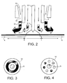
- Figure 2 is a schematic side view of a second apparatus for performing the method according to the invention;
- Figures 3 and 4 are schematic cross-sections through alternative forms of the apparatus shown in Figure 2;
- and Figure 5 is a schematic side view of a third apparatus for performing the method according to the invention.
-
- The drawings are not to scale.
- Referring to Figure 1 of the drawings, a conventional
MIG welding torch 2 is employed to weld togethermetal plates welding torch 2. Thewelding torch 2 feeds aconsumable electrode 8 to aweld zone 10. An electric arc is struck between the tip of theelectrode 8 and the ends of theplates weld zone 10. Molten metal is transferred from theelectrode 8 to theweld zone 10 through the arc. A shielding gas, typically consisting of argon, optionally with relatively small quantities of oxygen and carbon dioxide added, is supplied from the welding torch around theconsumable electrode 8 so as to inhibit oxidation of the weld metal. - As schematically shown in Figure 1, some small molten metal droplets are violently ejected from the region of the welding arc. This is the spatter that frequently bedevils commercial electric arc welding operations. In accordance with the invention, however, one or more jets of cryogenic coolant, preferably liquid nitrogen or carbon dioxide, are directed along a path through which the spatter travels as it is ejected from the welding arc. As shown in the drawing, two
nozzles 20 for the supply of liquid nitrogen are employed. If desired, however, moresuch nozzles 20 may be used. For example, there may be fournozzles 20 equally spaced from one another and all equidistant from the axis of thewelding torch 2. Thenozzles 20 may be connected by flexible hoses (not shown) to a source of liquid cryogen. In operation, jets of liquid nitrogen are directed at the spatter, the overall flow rate of the liquid nitrogen being selected so as to ensure that substantially none of the spatter adheres to the surfaces of theplates - The apparatus shown in Figure 2 is essentially the same as that shown in Figure 1 but with the exception that instead of employing
separate nozzles 20 for the supply of the jets of cryogen, the nozzles are built into thewelding torch 2 itself. Thus, the welding torch 2 (from which awire welding electrode 33 and a shieldinggas 35 issue) is provided with anouter passage 30 for theflow 31 of liquid cryogen terminating in anozzle 32. Thenozzle 32 may be of the kind shown in Figure 3 defining a single annular jet for the cryogen. Alternatively, thenozzle 32 may take the form shown in Figure 4 and comprise a plurality of circumferentially arranged jets. - In operation of the apparatus shown in Figure 2, the cryogen is supplied at a sufficient pressure to cause it to issue from the
nozzle 32 at such a velocity that it impacts against the proximate surfaces of theplates plates - The apparatus shown in Figure 5 is for the laser cutting or drilling of a
metal workpiece 40. The apparatus comprises a laser-cuttingtorch 42 of a conventional kind. In operation of the torch 42 a laser beam is focussed at a point on theworkpiece 40 where the cut is to be made. A cutting or process gas is supplied to that point with the laser beam. The cutting gas is typically oxygen. A plume of molten metal is ejected from the undersurface of theworkpiece 40 and tends to adhere to anundersurface 46. (If theworkpiece 40 is a tube, the undersurface will be the internal surface of the tube opposite the cut.) In accordance with the invention, anozzle 48 is arranged to direct a cryogenic coolant, typically either liquid nitrogen or solid carbon dioxide, in a jet at theplume 50 of molten metal particles that are ejected from the cut. The contact between the cryogen and the molten metal particles accelerates solidification of the latter with the result that their adherence to theundersurface 46 can be prevented. - In all the examples of the method according to the invention which have been described above with reference to the drawings, the use of a cryogenic liquid spray or a spray of solid carbon dioxide particles as a coolant to chill the molten metal particles results in these particles being cooled sufficiently by the latent heat of vaporization or sublimation and by the conductive effects of the very cold gas resulting from the vaporization or sublimation that the particles solidify while they are airborne. As a result the particles have insufficient residual heat to generate damage when they contact the surface of the workpiece or other component. This will result in much of the debris merely bouncing off the component's surface with no bonding between the two. A secondary effect is that the surface is itself cooled by the cryogen. In the event that a random particle of molten metal is not adequately cooled while airborne, cooling of the surface itself results in there being insufficient local temperature to create an effective interfacial bond between the particle and the surface.
- The method according to the invention has been tested experimentally in the laser cutting of a stainless steel plate having a thickness of 2mm. The cutting parameters were that the power of the laser-cutting torch was 1 kW, the speed of the cut was 3 metres per minute, the cutting gas was oxygen supplied at 3 bar, and the length of the cut was 200mm.
- A further stainless steel plate was placed 10mm vertically beneath the plate to be cut. When the cutting method was operated normally, i.e. without cooling of the plume of ejected molten metal particles, spatter was found to adhere to the stainless steel plate placed beneath the one being cut. On the other hand, when a single jet of solid carbon dioxide particles (formed by passing liquid carbon dioxide through a nozzle at a flow rate of 1 kg/min) was directed from the side at the plume of ejected particles of molten metal, there was no adherence of the spatter to the surface. But when a jet of compressed air at ambient temperature was substituted at a flow rate of 15 l/min for the jet of solid carbon dioxide particles, some spatter was found to adhere to the stainless steel surface. These experiments illustrate the importance of employing a cryogenic coolant as distinct from one at ambient temperature.
Claims (12)
- A method of working metal, in which molten metal particles are ejected, wherein the ejected molten metal particles are caused to pass through a contact region in which they make contact with a cryogen, the contact rendering the particles non-adherent to any adjacent surface, to which the particles would otherwise adhere, and/or the adjacent surface is cooled by contact with a cryogen so as to render the particles non-adherent thereto.
- A method as claimed in claim 1, in which the method is one of electric arc welding of metal workpieces.
- A method as claimed in claim 1, in which the method is one of laser welding of metal workpieces.
- A method as claimed in claim 1, in which the method is one for laser cutting or laser drilling of metal workpieces.
- A method as claimed in any one of the preceding claims, in which the cryogen is liquid nitrogen or solid carbon dioxide.
- A method according to any one of the preceding claims, in which the ejected molten metal particles are caused to make contact with the cryogen while they are airborne.
- A method according to any one of the preceding claims, in which the cryogen is deposited on a surface that is to be impacted by the ejected molten metal particles with the result that heat is transferred from the molten metal particles to the cryogen causing it to sublime.
- A method as claimed in claim 6, in which the ejected molten metal particles pass through at least one jet of cryogen.
- A method as claimed in claim 1, in which the method of working metal is a welding method, and a jet of cryogen is caused to contact the ejected molten metal particles from the side or from above the weld.
- A method as claimed in claim 9, in which there is employed a welding torch including an outer passage or passages for the supply of the cryogen.
- A method as claimed in claim 1, in which the method is a laser cutting, laser drilling or laser piercing method, and at least one jet of cryogen is directed from the side at the ejected particles of molten metal.
- A method as claimed in claim 11, in which the contact between the cryogen and the particles is made immediately adjacent the surface from which the particles are ejected.
Applications Claiming Priority (2)
| Application Number | Priority Date | Filing Date | Title |
|---|---|---|---|
| GBGB0209380.5A GB0209380D0 (en) | 2002-04-24 | 2002-04-24 | Metal working |
| GB0209380 | 2002-04-24 |
Publications (2)
| Publication Number | Publication Date |
|---|---|
| EP1356890A1 true EP1356890A1 (en) | 2003-10-29 |
| EP1356890B1 EP1356890B1 (en) | 2009-01-14 |
Family
ID=9935424
Family Applications (1)
| Application Number | Title | Priority Date | Filing Date |
|---|---|---|---|
| EP03252113A Expired - Lifetime EP1356890B1 (en) | 2002-04-24 | 2003-04-03 | Method of electric arc or laser welding of metal workpieces assisted by cryogen flow |
Country Status (8)
| Country | Link |
|---|---|
| US (1) | US7067759B2 (en) |
| EP (1) | EP1356890B1 (en) |
| AT (1) | ATE420746T1 (en) |
| AU (1) | AU2003203743A1 (en) |
| CA (1) | CA2424679A1 (en) |
| DE (1) | DE60325797D1 (en) |
| GB (1) | GB0209380D0 (en) |
| ZA (1) | ZA200302888B (en) |
Cited By (8)
| Publication number | Priority date | Publication date | Assignee | Title |
|---|---|---|---|---|
| EP1900469A1 (en) * | 2006-09-14 | 2008-03-19 | L'AIR LIQUIDE, Société Anonyme pour l'Etude et l'Exploitation des Procédés Georges Claude | Remote laser welding with sending of liquid argon as a protective atmosphere |
| EP1970154A1 (en) * | 2007-03-13 | 2008-09-17 | Linde Aktiengesellschaft | Method for thermal cutting and joining |
| EP2014400A1 (en) * | 2007-07-10 | 2009-01-14 | Linde AG | Method and device for welding metal workpieces |
| CN100463977C (en) * | 2006-07-31 | 2009-02-25 | 中国航天科技集团公司第五研究院第五一○研究所 | Gas protection method and device for laser surface modification in atmospheric environment |
| WO2009059776A1 (en) * | 2007-11-07 | 2009-05-14 | Trumpf Werkzeugmaschinen Gmbh & Co. Kg | Laser machining device comprising means for sprinkling and/or cooling an internal wall of a pipe, and method for machining a pipe by means of such a device |
| GB2455086A (en) * | 2007-11-27 | 2009-06-03 | Boc Group Plc | Weld Cooling |
| DE102008033797A1 (en) | 2008-07-18 | 2010-01-21 | Linde Ag | Welding device to thermally connect and separate metallic workpieces, comprises heat supply device for creating joint on workpieces, cooling device for cooling location on the joint and/or area directly above heat-supplied point, and robot |
| DE102024118274A1 (en) * | 2024-06-27 | 2025-12-31 | TRUMPF Werkzeugmaschinen SE + Co. KG | Method for laser cutting a workpiece with reduced slag adhesion |
Families Citing this family (12)
| Publication number | Priority date | Publication date | Assignee | Title |
|---|---|---|---|---|
| GB0418738D0 (en) * | 2004-08-23 | 2004-09-22 | 3M Innovative Properties Co | Medicinal aerosol formulation receptacle and production thereof |
| US20070175872A1 (en) * | 2006-01-27 | 2007-08-02 | Rhoades Lawrence J | Laser back wall protection by particulate shading |
| CA2696198A1 (en) * | 2007-08-14 | 2009-02-19 | Henkel Ag & Co. Kgaa | Body-in-white stamping lubricant with anti-weld spatter properties and related processes |
| DE102009057209B4 (en) * | 2009-02-09 | 2012-06-28 | Scansonic Mi Gmbh | Device with scanner optics for material processing by laser |
| US20100276397A1 (en) * | 2009-05-01 | 2010-11-04 | Baker Hughes Incorporated | Electrically isolated gas cups for plasma transfer arc welding torches, and related methods |
| US20120205354A1 (en) * | 2011-02-14 | 2012-08-16 | Texas Instruments Incorporated | Reducing dross welding phenomenon during irradiation engraving of a metal sheet |
| KR101199208B1 (en) | 2011-03-16 | 2012-11-07 | 삼성에스디아이 주식회사 | Removing device of spatter for laser welder |
| US9849537B2 (en) * | 2011-09-15 | 2017-12-26 | Linde Aktiengesellschaft | Methods for weld purging |
| US20130105561A1 (en) * | 2011-11-01 | 2013-05-02 | Amee Bay, Llc | Dry ice cleaning of metal surfaces to improve welding characteristics |
| US9358618B2 (en) | 2013-07-29 | 2016-06-07 | Globalfoundries Inc. | Implementing reduced drill smear |
| GB2527375A (en) * | 2014-06-20 | 2015-12-23 | Linde Ag | Welding apparatus |
| AU2024201409A1 (en) * | 2023-03-03 | 2024-09-19 | Relativity Space, Inc. | Systems and Methods for Welding Using Cryogenic Sources |
Citations (9)
| Publication number | Priority date | Publication date | Assignee | Title |
|---|---|---|---|---|
| US3122629A (en) * | 1962-02-05 | 1964-02-25 | Union Carbide Corp | Consumable electrode arcless electric working |
| JPS57138600A (en) * | 1981-02-20 | 1982-08-26 | Hitachi Ltd | Method of cutting and working hollow article |
| JPS5947084A (en) * | 1982-09-09 | 1984-03-16 | Mitsubishi Heavy Ind Ltd | Laser punching method |
| US4829859A (en) * | 1986-08-29 | 1989-05-16 | Ulticon Systems, Inc. | Method of high speed machining |
| JPH02268991A (en) * | 1989-04-11 | 1990-11-02 | Brother Ind Ltd | Laser welding method for galvanized steel sheets |
| DE3937460A1 (en) * | 1989-11-10 | 1990-11-08 | Daimler Benz Ag | METHOD FOR ATTACHING RESIDUE-FREE BREAK-FREE HOLES INTO THE WALL OF A FLUID PIPE |
| WO1999008830A1 (en) * | 1997-08-18 | 1999-02-25 | Zakrytoe Aktsionernoe Obschestvo 'firma Novye Sistemnye Tekhnologii' | Method of laser welding of thin sheet metallic components |
| EP1044762A2 (en) * | 1999-04-07 | 2000-10-18 | MULTIMATIC Oberflächentechnik GmbH & Co. | Method for removing the chips from a chip-producing machining process |
| FR2810913A1 (en) * | 2000-06-29 | 2002-01-04 | Air Liquide | Laser cutting of low-alloy steels without oxide formation on the cut surfaces involves passing a jet of cryogenic fluid in the direction of the cutting line |
Family Cites Families (11)
| Publication number | Priority date | Publication date | Assignee | Title |
|---|---|---|---|---|
| US2882385A (en) * | 1955-05-27 | 1959-04-14 | Air Reduction | Electric arc welding |
| JPS5285800A (en) | 1976-01-12 | 1977-07-16 | Toshiba Corp | Method of removing scattered material |
| JPS54126647A (en) * | 1978-03-27 | 1979-10-02 | Agency Of Ind Science & Technol | Working method by thermal shock |
| GB2168638A (en) | 1984-11-19 | 1986-06-25 | Control Laser Limited | Thermal cutting |
| JPH07100234B2 (en) | 1987-01-14 | 1995-11-01 | 株式会社ダイヘン | Laser beam cutting method for alloy steel |
| WO1989003274A1 (en) | 1987-10-14 | 1989-04-20 | Akademiet For De Tekniske Videnskaber, Svejsecentr | Method and application of laser drilling |
| DE3801068A1 (en) | 1988-01-15 | 1989-07-27 | Maho Ag | Method and apparatus for stock removal by means of bundled energy beams |
| US5073694A (en) | 1991-02-21 | 1991-12-17 | Synthes (U.S.A.) | Method and apparatus for laser cutting a hollow metal workpiece |
| DE4326517C2 (en) * | 1993-08-06 | 1998-06-10 | Linde Ag | Process for machining metal workpieces with cooling |
| AU5676599A (en) * | 1998-08-18 | 2000-03-14 | Lockheed Martin Corporation | Automated barrel panel transfer and processing system |
| GB0010793D0 (en) * | 2000-05-03 | 2000-06-28 | Boc Group Plc | Improvements in thermal welding |
-
2002
- 2002-04-24 GB GBGB0209380.5A patent/GB0209380D0/en not_active Ceased
-
2003
- 2003-04-03 DE DE60325797T patent/DE60325797D1/en not_active Expired - Fee Related
- 2003-04-03 EP EP03252113A patent/EP1356890B1/en not_active Expired - Lifetime
- 2003-04-03 AT AT03252113T patent/ATE420746T1/en not_active IP Right Cessation
- 2003-04-08 CA CA002424679A patent/CA2424679A1/en not_active Abandoned
- 2003-04-11 ZA ZA200302888A patent/ZA200302888B/en unknown
- 2003-04-16 AU AU2003203743A patent/AU2003203743A1/en not_active Abandoned
- 2003-04-23 US US10/421,233 patent/US7067759B2/en not_active Expired - Fee Related
Patent Citations (9)
| Publication number | Priority date | Publication date | Assignee | Title |
|---|---|---|---|---|
| US3122629A (en) * | 1962-02-05 | 1964-02-25 | Union Carbide Corp | Consumable electrode arcless electric working |
| JPS57138600A (en) * | 1981-02-20 | 1982-08-26 | Hitachi Ltd | Method of cutting and working hollow article |
| JPS5947084A (en) * | 1982-09-09 | 1984-03-16 | Mitsubishi Heavy Ind Ltd | Laser punching method |
| US4829859A (en) * | 1986-08-29 | 1989-05-16 | Ulticon Systems, Inc. | Method of high speed machining |
| JPH02268991A (en) * | 1989-04-11 | 1990-11-02 | Brother Ind Ltd | Laser welding method for galvanized steel sheets |
| DE3937460A1 (en) * | 1989-11-10 | 1990-11-08 | Daimler Benz Ag | METHOD FOR ATTACHING RESIDUE-FREE BREAK-FREE HOLES INTO THE WALL OF A FLUID PIPE |
| WO1999008830A1 (en) * | 1997-08-18 | 1999-02-25 | Zakrytoe Aktsionernoe Obschestvo 'firma Novye Sistemnye Tekhnologii' | Method of laser welding of thin sheet metallic components |
| EP1044762A2 (en) * | 1999-04-07 | 2000-10-18 | MULTIMATIC Oberflächentechnik GmbH & Co. | Method for removing the chips from a chip-producing machining process |
| FR2810913A1 (en) * | 2000-06-29 | 2002-01-04 | Air Liquide | Laser cutting of low-alloy steels without oxide formation on the cut surfaces involves passing a jet of cryogenic fluid in the direction of the cutting line |
Non-Patent Citations (2)
| Title |
|---|
| PATENT ABSTRACTS OF JAPAN vol. 008, no. 152 (M - 309) 14 July 1984 (1984-07-14) * |
| PATENT ABSTRACTS OF JAPAN vol. 015, no. 025 (M - 1071) 21 January 1991 (1991-01-21) * |
Cited By (12)
| Publication number | Priority date | Publication date | Assignee | Title |
|---|---|---|---|---|
| CN100463977C (en) * | 2006-07-31 | 2009-02-25 | 中国航天科技集团公司第五研究院第五一○研究所 | Gas protection method and device for laser surface modification in atmospheric environment |
| EP1900469A1 (en) * | 2006-09-14 | 2008-03-19 | L'AIR LIQUIDE, Société Anonyme pour l'Etude et l'Exploitation des Procédés Georges Claude | Remote laser welding with sending of liquid argon as a protective atmosphere |
| FR2905884A1 (en) * | 2006-09-14 | 2008-03-21 | Air Liquide | REMOTE LASER WELDING WITH ARGON SENDING AS A PROTECTIVE ATMOSPHERE |
| EP1970154A1 (en) * | 2007-03-13 | 2008-09-17 | Linde Aktiengesellschaft | Method for thermal cutting and joining |
| EP2014400A1 (en) * | 2007-07-10 | 2009-01-14 | Linde AG | Method and device for welding metal workpieces |
| EP2014401A1 (en) * | 2007-07-10 | 2009-01-14 | Linde AG | Method and device for welding workpieces |
| US20090014422A1 (en) * | 2007-07-10 | 2009-01-15 | Linde Ag | Device and Method for Welding Workpieces |
| WO2009059776A1 (en) * | 2007-11-07 | 2009-05-14 | Trumpf Werkzeugmaschinen Gmbh & Co. Kg | Laser machining device comprising means for sprinkling and/or cooling an internal wall of a pipe, and method for machining a pipe by means of such a device |
| GB2455086A (en) * | 2007-11-27 | 2009-06-03 | Boc Group Plc | Weld Cooling |
| GB2455086B (en) * | 2007-11-27 | 2010-02-10 | Boc Group Plc | Weld cooling |
| DE102008033797A1 (en) | 2008-07-18 | 2010-01-21 | Linde Ag | Welding device to thermally connect and separate metallic workpieces, comprises heat supply device for creating joint on workpieces, cooling device for cooling location on the joint and/or area directly above heat-supplied point, and robot |
| DE102024118274A1 (en) * | 2024-06-27 | 2025-12-31 | TRUMPF Werkzeugmaschinen SE + Co. KG | Method for laser cutting a workpiece with reduced slag adhesion |
Also Published As
| Publication number | Publication date |
|---|---|
| DE60325797D1 (en) | 2009-03-05 |
| EP1356890B1 (en) | 2009-01-14 |
| US7067759B2 (en) | 2006-06-27 |
| ZA200302888B (en) | 2003-10-15 |
| GB0209380D0 (en) | 2002-06-05 |
| AU2003203743A1 (en) | 2003-11-13 |
| ATE420746T1 (en) | 2009-01-15 |
| CA2424679A1 (en) | 2003-10-24 |
| US20030222060A1 (en) | 2003-12-04 |
Similar Documents
| Publication | Publication Date | Title |
|---|---|---|
| US7067759B2 (en) | Metal working | |
| US9289855B2 (en) | Sheet metal piece having weld notch and method of forming the same | |
| EP1018395B1 (en) | Laser machining apparatus | |
| JP3385361B2 (en) | Laser welding method and laser welding apparatus | |
| US20080116175A1 (en) | Laser welding process with improved penetration | |
| US20090107970A1 (en) | Method for controlling weld quality | |
| NZ547868A (en) | Tig welding or braze-welding with metal transfer via a liquid bridge | |
| EP1454701A8 (en) | Hybrid laser-arc welding method for welding zinc coated steel | |
| Samarjy et al. | Using laser cutting as a source of molten droplets for additive manufacturing: A new recycling technique | |
| KR20130135933A (en) | Gas tungsten arc welding using flux coated electrodes | |
| JP2004306106A (en) | Laser beam machining head | |
| WO2013110214A1 (en) | Method of welding coated materials | |
| JP5692293B2 (en) | Laser welding method and laser welding apparatus for metal plate | |
| JP5122986B2 (en) | Laser welding method and apparatus for steel plate | |
| JP5741663B2 (en) | Laser welding method and apparatus for steel plate | |
| EP1970154A1 (en) | Method for thermal cutting and joining | |
| US20110210106A1 (en) | Method For Laser Fusion Cutting Without Cutting Gas | |
| KR100627486B1 (en) | Metal plate cutting device and method | |
| JP2004009096A (en) | Laser welding device | |
| JP5396941B2 (en) | Laser welding method and laser welding apparatus for metal plate | |
| WO2007144673A1 (en) | Weld cooling | |
| GB2142858A (en) | Spray welding of metals | |
| JP5488651B2 (en) | Laser welding method and apparatus for steel plate | |
| JP4775699B2 (en) | Laser double-sided groove processing apparatus and double-sided groove processing method | |
| Üstündağ et al. | Influence of an external applied AC magnetic field on the melt pool dynamics at high-power laser beam welding |
Legal Events
| Date | Code | Title | Description |
|---|---|---|---|
| PUAI | Public reference made under article 153(3) epc to a published international application that has entered the european phase |
Free format text: ORIGINAL CODE: 0009012 |
|
| AK | Designated contracting states |
Kind code of ref document: A1 Designated state(s): AT BE BG CH CY CZ DE DK EE ES FI FR GB GR HU IE IT LI LU MC NL PT RO SE SI SK TR |
|
| AX | Request for extension of the european patent |
Extension state: AL LT LV MK |
|
| 17P | Request for examination filed |
Effective date: 20040408 |
|
| AKX | Designation fees paid |
Designated state(s): AT BE BG CH CY CZ DE DK EE ES FI FR GB GR HU IE IT LI LU MC NL PT RO SE SI SK TR |
|
| 17Q | First examination report despatched |
Effective date: 20040920 |
|
| 17Q | First examination report despatched |
Effective date: 20040920 |
|
| GRAP | Despatch of communication of intention to grant a patent |
Free format text: ORIGINAL CODE: EPIDOSNIGR1 |
|
| RTI1 | Title (correction) |
Free format text: METHOD OF ELECTRIC ARC OR LASER WELDING OF METAL WORKPIECES ASSISTED BY CRYOGEN FLOW |
|
| RAP1 | Party data changed (applicant data changed or rights of an application transferred) |
Owner name: THE BOC GROUP LIMITED |
|
| GRAS | Grant fee paid |
Free format text: ORIGINAL CODE: EPIDOSNIGR3 |
|
| GRAA | (expected) grant |
Free format text: ORIGINAL CODE: 0009210 |
|
| AK | Designated contracting states |
Kind code of ref document: B1 Designated state(s): AT BE BG CH CY CZ DE DK EE ES FI FR GB GR HU IE IT LI LU MC NL PT RO SE SI SK TR |
|
| REG | Reference to a national code |
Ref country code: GB Ref legal event code: FG4D |
|
| REG | Reference to a national code |
Ref country code: CH Ref legal event code: EP |
|
| REG | Reference to a national code |
Ref country code: IE Ref legal event code: FG4D |
|
| REF | Corresponds to: |
Ref document number: 60325797 Country of ref document: DE Date of ref document: 20090305 Kind code of ref document: P |
|
| PG25 | Lapsed in a contracting state [announced via postgrant information from national office to epo] |
Ref country code: NL Free format text: LAPSE BECAUSE OF FAILURE TO SUBMIT A TRANSLATION OF THE DESCRIPTION OR TO PAY THE FEE WITHIN THE PRESCRIBED TIME-LIMIT Effective date: 20090114 |
|
| NLV1 | Nl: lapsed or annulled due to failure to fulfill the requirements of art. 29p and 29m of the patents act | ||
| PG25 | Lapsed in a contracting state [announced via postgrant information from national office to epo] |
Ref country code: SI Free format text: LAPSE BECAUSE OF FAILURE TO SUBMIT A TRANSLATION OF THE DESCRIPTION OR TO PAY THE FEE WITHIN THE PRESCRIBED TIME-LIMIT Effective date: 20090114 Ref country code: ES Free format text: LAPSE BECAUSE OF FAILURE TO SUBMIT A TRANSLATION OF THE DESCRIPTION OR TO PAY THE FEE WITHIN THE PRESCRIBED TIME-LIMIT Effective date: 20090425 Ref country code: FI Free format text: LAPSE BECAUSE OF FAILURE TO SUBMIT A TRANSLATION OF THE DESCRIPTION OR TO PAY THE FEE WITHIN THE PRESCRIBED TIME-LIMIT Effective date: 20090114 |
|
| PG25 | Lapsed in a contracting state [announced via postgrant information from national office to epo] |
Ref country code: SE Free format text: LAPSE BECAUSE OF FAILURE TO SUBMIT A TRANSLATION OF THE DESCRIPTION OR TO PAY THE FEE WITHIN THE PRESCRIBED TIME-LIMIT Effective date: 20090414 Ref country code: PT Free format text: LAPSE BECAUSE OF FAILURE TO SUBMIT A TRANSLATION OF THE DESCRIPTION OR TO PAY THE FEE WITHIN THE PRESCRIBED TIME-LIMIT Effective date: 20090615 Ref country code: AT Free format text: LAPSE BECAUSE OF FAILURE TO SUBMIT A TRANSLATION OF THE DESCRIPTION OR TO PAY THE FEE WITHIN THE PRESCRIBED TIME-LIMIT Effective date: 20090114 |
|
| PG25 | Lapsed in a contracting state [announced via postgrant information from national office to epo] |
Ref country code: BE Free format text: LAPSE BECAUSE OF FAILURE TO SUBMIT A TRANSLATION OF THE DESCRIPTION OR TO PAY THE FEE WITHIN THE PRESCRIBED TIME-LIMIT Effective date: 20090114 |
|
| PG25 | Lapsed in a contracting state [announced via postgrant information from national office to epo] |
Ref country code: DK Free format text: LAPSE BECAUSE OF FAILURE TO SUBMIT A TRANSLATION OF THE DESCRIPTION OR TO PAY THE FEE WITHIN THE PRESCRIBED TIME-LIMIT Effective date: 20090114 Ref country code: EE Free format text: LAPSE BECAUSE OF FAILURE TO SUBMIT A TRANSLATION OF THE DESCRIPTION OR TO PAY THE FEE WITHIN THE PRESCRIBED TIME-LIMIT Effective date: 20090114 Ref country code: CZ Free format text: LAPSE BECAUSE OF FAILURE TO SUBMIT A TRANSLATION OF THE DESCRIPTION OR TO PAY THE FEE WITHIN THE PRESCRIBED TIME-LIMIT Effective date: 20090114 |
|
| PLBE | No opposition filed within time limit |
Free format text: ORIGINAL CODE: 0009261 |
|
| STAA | Information on the status of an ep patent application or granted ep patent |
Free format text: STATUS: NO OPPOSITION FILED WITHIN TIME LIMIT |
|
| PG25 | Lapsed in a contracting state [announced via postgrant information from national office to epo] |
Ref country code: SK Free format text: LAPSE BECAUSE OF FAILURE TO SUBMIT A TRANSLATION OF THE DESCRIPTION OR TO PAY THE FEE WITHIN THE PRESCRIBED TIME-LIMIT Effective date: 20090114 Ref country code: RO Free format text: LAPSE BECAUSE OF FAILURE TO SUBMIT A TRANSLATION OF THE DESCRIPTION OR TO PAY THE FEE WITHIN THE PRESCRIBED TIME-LIMIT Effective date: 20090114 |
|
| REG | Reference to a national code |
Ref country code: CH Ref legal event code: PL |
|
| 26N | No opposition filed |
Effective date: 20091015 |
|
| GBPC | Gb: european patent ceased through non-payment of renewal fee |
Effective date: 20090414 |
|
| REG | Reference to a national code |
Ref country code: FR Ref legal event code: ST Effective date: 20091231 |
|
| PG25 | Lapsed in a contracting state [announced via postgrant information from national office to epo] |
Ref country code: DE Free format text: LAPSE BECAUSE OF NON-PAYMENT OF DUE FEES Effective date: 20091103 Ref country code: LI Free format text: LAPSE BECAUSE OF NON-PAYMENT OF DUE FEES Effective date: 20090430 Ref country code: BG Free format text: LAPSE BECAUSE OF FAILURE TO SUBMIT A TRANSLATION OF THE DESCRIPTION OR TO PAY THE FEE WITHIN THE PRESCRIBED TIME-LIMIT Effective date: 20090414 Ref country code: CH Free format text: LAPSE BECAUSE OF NON-PAYMENT OF DUE FEES Effective date: 20090430 |
|
| REG | Reference to a national code |
Ref country code: IE Ref legal event code: MM4A |
|
| PG25 | Lapsed in a contracting state [announced via postgrant information from national office to epo] |
Ref country code: MC Free format text: LAPSE BECAUSE OF NON-PAYMENT OF DUE FEES Effective date: 20090430 Ref country code: FR Free format text: LAPSE BECAUSE OF NON-PAYMENT OF DUE FEES Effective date: 20091222 Ref country code: IE Free format text: LAPSE BECAUSE OF NON-PAYMENT OF DUE FEES Effective date: 20090403 Ref country code: GB Free format text: LAPSE BECAUSE OF NON-PAYMENT OF DUE FEES Effective date: 20090414 |
|
| PG25 | Lapsed in a contracting state [announced via postgrant information from national office to epo] |
Ref country code: GR Free format text: LAPSE BECAUSE OF FAILURE TO SUBMIT A TRANSLATION OF THE DESCRIPTION OR TO PAY THE FEE WITHIN THE PRESCRIBED TIME-LIMIT Effective date: 20090415 |
|
| PG25 | Lapsed in a contracting state [announced via postgrant information from national office to epo] |
Ref country code: IT Free format text: LAPSE BECAUSE OF FAILURE TO SUBMIT A TRANSLATION OF THE DESCRIPTION OR TO PAY THE FEE WITHIN THE PRESCRIBED TIME-LIMIT Effective date: 20090114 |
|
| PG25 | Lapsed in a contracting state [announced via postgrant information from national office to epo] |
Ref country code: LU Free format text: LAPSE BECAUSE OF NON-PAYMENT OF DUE FEES Effective date: 20090403 |
|
| PG25 | Lapsed in a contracting state [announced via postgrant information from national office to epo] |
Ref country code: HU Free format text: LAPSE BECAUSE OF FAILURE TO SUBMIT A TRANSLATION OF THE DESCRIPTION OR TO PAY THE FEE WITHIN THE PRESCRIBED TIME-LIMIT Effective date: 20090715 |
|
| PG25 | Lapsed in a contracting state [announced via postgrant information from national office to epo] |
Ref country code: TR Free format text: LAPSE BECAUSE OF FAILURE TO SUBMIT A TRANSLATION OF THE DESCRIPTION OR TO PAY THE FEE WITHIN THE PRESCRIBED TIME-LIMIT Effective date: 20090114 |
|
| PG25 | Lapsed in a contracting state [announced via postgrant information from national office to epo] |
Ref country code: CY Free format text: LAPSE BECAUSE OF FAILURE TO SUBMIT A TRANSLATION OF THE DESCRIPTION OR TO PAY THE FEE WITHIN THE PRESCRIBED TIME-LIMIT Effective date: 20090114 |