EP1357342A1 - Drei-Säulen-System zur Tieftemperaturzerlegung mit Argongewinnung - Google Patents
Drei-Säulen-System zur Tieftemperaturzerlegung mit Argongewinnung Download PDFInfo
- Publication number
- EP1357342A1 EP1357342A1 EP02011458A EP02011458A EP1357342A1 EP 1357342 A1 EP1357342 A1 EP 1357342A1 EP 02011458 A EP02011458 A EP 02011458A EP 02011458 A EP02011458 A EP 02011458A EP 1357342 A1 EP1357342 A1 EP 1357342A1
- Authority
- EP
- European Patent Office
- Prior art keywords
- argon
- column
- pressure column
- nitrogen
- low
- Prior art date
- Legal status (The legal status is an assumption and is not a legal conclusion. Google has not performed a legal analysis and makes no representation as to the accuracy of the status listed.)
- Granted
Links
- XKRFYHLGVUSROY-UHFFFAOYSA-N Argon Chemical compound [Ar] XKRFYHLGVUSROY-UHFFFAOYSA-N 0.000 title claims abstract description 194
- 229910052786 argon Inorganic materials 0.000 title claims abstract description 98
- 238000000926 separation method Methods 0.000 title claims description 17
- 238000011084 recovery Methods 0.000 title description 2
- IJGRMHOSHXDMSA-UHFFFAOYSA-N Atomic nitrogen Chemical compound N#N IJGRMHOSHXDMSA-UHFFFAOYSA-N 0.000 claims abstract description 39
- 238000000034 method Methods 0.000 claims abstract description 30
- 239000001301 oxygen Substances 0.000 claims abstract description 23
- 229910052760 oxygen Inorganic materials 0.000 claims abstract description 23
- QVGXLLKOCUKJST-UHFFFAOYSA-N atomic oxygen Chemical compound [O] QVGXLLKOCUKJST-UHFFFAOYSA-N 0.000 claims abstract description 22
- 229910052757 nitrogen Inorganic materials 0.000 claims abstract description 19
- 239000007788 liquid Substances 0.000 claims description 25
- DOTMOQHOJINYBL-UHFFFAOYSA-N molecular nitrogen;molecular oxygen Chemical compound N#N.O=O DOTMOQHOJINYBL-UHFFFAOYSA-N 0.000 claims description 10
- 238000011144 upstream manufacturing Methods 0.000 claims description 8
- 239000007789 gas Substances 0.000 abstract description 6
- 239000003570 air Substances 0.000 abstract 3
- 239000012080 ambient air Substances 0.000 abstract 1
- 238000000605 extraction Methods 0.000 abstract 1
- 229940110728 nitrogen / oxygen Drugs 0.000 abstract 1
- 238000004519 manufacturing process Methods 0.000 description 5
- 230000006835 compression Effects 0.000 description 4
- 238000007906 compression Methods 0.000 description 4
- 238000001816 cooling Methods 0.000 description 4
- 238000010438 heat treatment Methods 0.000 description 4
- 239000002689 soil Substances 0.000 description 3
- MYMOFIZGZYHOMD-UHFFFAOYSA-N Dioxygen Chemical compound O=O MYMOFIZGZYHOMD-UHFFFAOYSA-N 0.000 description 2
- 150000001485 argon Chemical class 0.000 description 2
- 238000007664 blowing Methods 0.000 description 2
- 238000001704 evaporation Methods 0.000 description 2
- 238000005086 pumping Methods 0.000 description 2
- 238000004781 supercooling Methods 0.000 description 2
- 230000007704 transition Effects 0.000 description 2
- 206010016352 Feeling of relaxation Diseases 0.000 description 1
- 241000883306 Huso huso Species 0.000 description 1
- 210000001015 abdomen Anatomy 0.000 description 1
- 239000003990 capacitor Substances 0.000 description 1
- 238000004140 cleaning Methods 0.000 description 1
- 150000001875 compounds Chemical class 0.000 description 1
- 229910001873 dinitrogen Inorganic materials 0.000 description 1
- 230000005611 electricity Effects 0.000 description 1
- 238000005516 engineering process Methods 0.000 description 1
- 230000008020 evaporation Effects 0.000 description 1
- 239000012530 fluid Substances 0.000 description 1
- 238000011010 flushing procedure Methods 0.000 description 1
- 230000002631 hypothermal effect Effects 0.000 description 1
- 230000004048 modification Effects 0.000 description 1
- 238000012986 modification Methods 0.000 description 1
- 238000005057 refrigeration Methods 0.000 description 1
Images


Classifications
-
- F—MECHANICAL ENGINEERING; LIGHTING; HEATING; WEAPONS; BLASTING
- F25—REFRIGERATION OR COOLING; COMBINED HEATING AND REFRIGERATION SYSTEMS; HEAT PUMP SYSTEMS; MANUFACTURE OR STORAGE OF ICE; LIQUEFACTION SOLIDIFICATION OF GASES
- F25J—LIQUEFACTION, SOLIDIFICATION OR SEPARATION OF GASES OR GASEOUS OR LIQUEFIED GASEOUS MIXTURES BY PRESSURE AND COLD TREATMENT OR BY BRINGING THEM INTO THE SUPERCRITICAL STATE
- F25J3/00—Processes or apparatus for separating the constituents of gaseous or liquefied gaseous mixtures involving the use of liquefaction or solidification
- F25J3/02—Processes or apparatus for separating the constituents of gaseous or liquefied gaseous mixtures involving the use of liquefaction or solidification by rectification, i.e. by continuous interchange of heat and material between a vapour stream and a liquid stream
- F25J3/04—Processes or apparatus for separating the constituents of gaseous or liquefied gaseous mixtures involving the use of liquefaction or solidification by rectification, i.e. by continuous interchange of heat and material between a vapour stream and a liquid stream for air
- F25J3/04151—Purification and (pre-)cooling of the feed air; recuperative heat-exchange with product streams
- F25J3/04187—Cooling of the purified feed air by recuperative heat-exchange; Heat-exchange with product streams
- F25J3/04193—Division of the main heat exchange line in consecutive sections having different functions
- F25J3/04206—Division of the main heat exchange line in consecutive sections having different functions including a so-called "auxiliary vaporiser" for vaporising and producing a gaseous product
- F25J3/04212—Division of the main heat exchange line in consecutive sections having different functions including a so-called "auxiliary vaporiser" for vaporising and producing a gaseous product and simultaneously condensing vapor from a column serving as reflux within the or another column
-
- F—MECHANICAL ENGINEERING; LIGHTING; HEATING; WEAPONS; BLASTING
- F25—REFRIGERATION OR COOLING; COMBINED HEATING AND REFRIGERATION SYSTEMS; HEAT PUMP SYSTEMS; MANUFACTURE OR STORAGE OF ICE; LIQUEFACTION SOLIDIFICATION OF GASES
- F25J—LIQUEFACTION, SOLIDIFICATION OR SEPARATION OF GASES OR GASEOUS OR LIQUEFIED GASEOUS MIXTURES BY PRESSURE AND COLD TREATMENT OR BY BRINGING THEM INTO THE SUPERCRITICAL STATE
- F25J3/00—Processes or apparatus for separating the constituents of gaseous or liquefied gaseous mixtures involving the use of liquefaction or solidification
- F25J3/02—Processes or apparatus for separating the constituents of gaseous or liquefied gaseous mixtures involving the use of liquefaction or solidification by rectification, i.e. by continuous interchange of heat and material between a vapour stream and a liquid stream
- F25J3/04—Processes or apparatus for separating the constituents of gaseous or liquefied gaseous mixtures involving the use of liquefaction or solidification by rectification, i.e. by continuous interchange of heat and material between a vapour stream and a liquid stream for air
- F25J3/04006—Providing pressurised feed air or process streams within or from the air fractionation unit
- F25J3/04078—Providing pressurised feed air or process streams within or from the air fractionation unit providing pressurized products by liquid compression and vaporisation with cold recovery, i.e. so-called internal compression
- F25J3/0409—Providing pressurised feed air or process streams within or from the air fractionation unit providing pressurized products by liquid compression and vaporisation with cold recovery, i.e. so-called internal compression of oxygen
-
- F—MECHANICAL ENGINEERING; LIGHTING; HEATING; WEAPONS; BLASTING
- F25—REFRIGERATION OR COOLING; COMBINED HEATING AND REFRIGERATION SYSTEMS; HEAT PUMP SYSTEMS; MANUFACTURE OR STORAGE OF ICE; LIQUEFACTION SOLIDIFICATION OF GASES
- F25J—LIQUEFACTION, SOLIDIFICATION OR SEPARATION OF GASES OR GASEOUS OR LIQUEFIED GASEOUS MIXTURES BY PRESSURE AND COLD TREATMENT OR BY BRINGING THEM INTO THE SUPERCRITICAL STATE
- F25J3/00—Processes or apparatus for separating the constituents of gaseous or liquefied gaseous mixtures involving the use of liquefaction or solidification
- F25J3/02—Processes or apparatus for separating the constituents of gaseous or liquefied gaseous mixtures involving the use of liquefaction or solidification by rectification, i.e. by continuous interchange of heat and material between a vapour stream and a liquid stream
- F25J3/04—Processes or apparatus for separating the constituents of gaseous or liquefied gaseous mixtures involving the use of liquefaction or solidification by rectification, i.e. by continuous interchange of heat and material between a vapour stream and a liquid stream for air
- F25J3/04151—Purification and (pre-)cooling of the feed air; recuperative heat-exchange with product streams
- F25J3/04187—Cooling of the purified feed air by recuperative heat-exchange; Heat-exchange with product streams
- F25J3/0423—Subcooling of liquid process streams
-
- F—MECHANICAL ENGINEERING; LIGHTING; HEATING; WEAPONS; BLASTING
- F25—REFRIGERATION OR COOLING; COMBINED HEATING AND REFRIGERATION SYSTEMS; HEAT PUMP SYSTEMS; MANUFACTURE OR STORAGE OF ICE; LIQUEFACTION SOLIDIFICATION OF GASES
- F25J—LIQUEFACTION, SOLIDIFICATION OR SEPARATION OF GASES OR GASEOUS OR LIQUEFIED GASEOUS MIXTURES BY PRESSURE AND COLD TREATMENT OR BY BRINGING THEM INTO THE SUPERCRITICAL STATE
- F25J3/00—Processes or apparatus for separating the constituents of gaseous or liquefied gaseous mixtures involving the use of liquefaction or solidification
- F25J3/02—Processes or apparatus for separating the constituents of gaseous or liquefied gaseous mixtures involving the use of liquefaction or solidification by rectification, i.e. by continuous interchange of heat and material between a vapour stream and a liquid stream
- F25J3/04—Processes or apparatus for separating the constituents of gaseous or liquefied gaseous mixtures involving the use of liquefaction or solidification by rectification, i.e. by continuous interchange of heat and material between a vapour stream and a liquid stream for air
- F25J3/04248—Generation of cold for compensating heat leaks or liquid production, e.g. by Joule-Thompson expansion
- F25J3/04284—Generation of cold for compensating heat leaks or liquid production, e.g. by Joule-Thompson expansion using internal refrigeration by open-loop gas work expansion, e.g. of intermediate or oxygen enriched (waste-)streams
- F25J3/0429—Generation of cold for compensating heat leaks or liquid production, e.g. by Joule-Thompson expansion using internal refrigeration by open-loop gas work expansion, e.g. of intermediate or oxygen enriched (waste-)streams of feed air, e.g. used as waste or product air or expanded into an auxiliary column
- F25J3/04303—Lachmann expansion, i.e. expanded into oxygen producing or low pressure column
-
- F—MECHANICAL ENGINEERING; LIGHTING; HEATING; WEAPONS; BLASTING
- F25—REFRIGERATION OR COOLING; COMBINED HEATING AND REFRIGERATION SYSTEMS; HEAT PUMP SYSTEMS; MANUFACTURE OR STORAGE OF ICE; LIQUEFACTION SOLIDIFICATION OF GASES
- F25J—LIQUEFACTION, SOLIDIFICATION OR SEPARATION OF GASES OR GASEOUS OR LIQUEFIED GASEOUS MIXTURES BY PRESSURE AND COLD TREATMENT OR BY BRINGING THEM INTO THE SUPERCRITICAL STATE
- F25J3/00—Processes or apparatus for separating the constituents of gaseous or liquefied gaseous mixtures involving the use of liquefaction or solidification
- F25J3/02—Processes or apparatus for separating the constituents of gaseous or liquefied gaseous mixtures involving the use of liquefaction or solidification by rectification, i.e. by continuous interchange of heat and material between a vapour stream and a liquid stream
- F25J3/04—Processes or apparatus for separating the constituents of gaseous or liquefied gaseous mixtures involving the use of liquefaction or solidification by rectification, i.e. by continuous interchange of heat and material between a vapour stream and a liquid stream for air
- F25J3/04248—Generation of cold for compensating heat leaks or liquid production, e.g. by Joule-Thompson expansion
- F25J3/04284—Generation of cold for compensating heat leaks or liquid production, e.g. by Joule-Thompson expansion using internal refrigeration by open-loop gas work expansion, e.g. of intermediate or oxygen enriched (waste-)streams
- F25J3/04309—Generation of cold for compensating heat leaks or liquid production, e.g. by Joule-Thompson expansion using internal refrigeration by open-loop gas work expansion, e.g. of intermediate or oxygen enriched (waste-)streams of nitrogen
-
- F—MECHANICAL ENGINEERING; LIGHTING; HEATING; WEAPONS; BLASTING
- F25—REFRIGERATION OR COOLING; COMBINED HEATING AND REFRIGERATION SYSTEMS; HEAT PUMP SYSTEMS; MANUFACTURE OR STORAGE OF ICE; LIQUEFACTION SOLIDIFICATION OF GASES
- F25J—LIQUEFACTION, SOLIDIFICATION OR SEPARATION OF GASES OR GASEOUS OR LIQUEFIED GASEOUS MIXTURES BY PRESSURE AND COLD TREATMENT OR BY BRINGING THEM INTO THE SUPERCRITICAL STATE
- F25J3/00—Processes or apparatus for separating the constituents of gaseous or liquefied gaseous mixtures involving the use of liquefaction or solidification
- F25J3/02—Processes or apparatus for separating the constituents of gaseous or liquefied gaseous mixtures involving the use of liquefaction or solidification by rectification, i.e. by continuous interchange of heat and material between a vapour stream and a liquid stream
- F25J3/04—Processes or apparatus for separating the constituents of gaseous or liquefied gaseous mixtures involving the use of liquefaction or solidification by rectification, i.e. by continuous interchange of heat and material between a vapour stream and a liquid stream for air
- F25J3/04248—Generation of cold for compensating heat leaks or liquid production, e.g. by Joule-Thompson expansion
- F25J3/04284—Generation of cold for compensating heat leaks or liquid production, e.g. by Joule-Thompson expansion using internal refrigeration by open-loop gas work expansion, e.g. of intermediate or oxygen enriched (waste-)streams
- F25J3/04327—Generation of cold for compensating heat leaks or liquid production, e.g. by Joule-Thompson expansion using internal refrigeration by open-loop gas work expansion, e.g. of intermediate or oxygen enriched (waste-)streams of argon or argon enriched stream
-
- F—MECHANICAL ENGINEERING; LIGHTING; HEATING; WEAPONS; BLASTING
- F25—REFRIGERATION OR COOLING; COMBINED HEATING AND REFRIGERATION SYSTEMS; HEAT PUMP SYSTEMS; MANUFACTURE OR STORAGE OF ICE; LIQUEFACTION SOLIDIFICATION OF GASES
- F25J—LIQUEFACTION, SOLIDIFICATION OR SEPARATION OF GASES OR GASEOUS OR LIQUEFIED GASEOUS MIXTURES BY PRESSURE AND COLD TREATMENT OR BY BRINGING THEM INTO THE SUPERCRITICAL STATE
- F25J3/00—Processes or apparatus for separating the constituents of gaseous or liquefied gaseous mixtures involving the use of liquefaction or solidification
- F25J3/02—Processes or apparatus for separating the constituents of gaseous or liquefied gaseous mixtures involving the use of liquefaction or solidification by rectification, i.e. by continuous interchange of heat and material between a vapour stream and a liquid stream
- F25J3/04—Processes or apparatus for separating the constituents of gaseous or liquefied gaseous mixtures involving the use of liquefaction or solidification by rectification, i.e. by continuous interchange of heat and material between a vapour stream and a liquid stream for air
- F25J3/04248—Generation of cold for compensating heat leaks or liquid production, e.g. by Joule-Thompson expansion
- F25J3/04375—Details relating to the work expansion, e.g. process parameter etc.
- F25J3/04393—Details relating to the work expansion, e.g. process parameter etc. using multiple or multistage gas work expansion
-
- F—MECHANICAL ENGINEERING; LIGHTING; HEATING; WEAPONS; BLASTING
- F25—REFRIGERATION OR COOLING; COMBINED HEATING AND REFRIGERATION SYSTEMS; HEAT PUMP SYSTEMS; MANUFACTURE OR STORAGE OF ICE; LIQUEFACTION SOLIDIFICATION OF GASES
- F25J—LIQUEFACTION, SOLIDIFICATION OR SEPARATION OF GASES OR GASEOUS OR LIQUEFIED GASEOUS MIXTURES BY PRESSURE AND COLD TREATMENT OR BY BRINGING THEM INTO THE SUPERCRITICAL STATE
- F25J3/00—Processes or apparatus for separating the constituents of gaseous or liquefied gaseous mixtures involving the use of liquefaction or solidification
- F25J3/02—Processes or apparatus for separating the constituents of gaseous or liquefied gaseous mixtures involving the use of liquefaction or solidification by rectification, i.e. by continuous interchange of heat and material between a vapour stream and a liquid stream
- F25J3/04—Processes or apparatus for separating the constituents of gaseous or liquefied gaseous mixtures involving the use of liquefaction or solidification by rectification, i.e. by continuous interchange of heat and material between a vapour stream and a liquid stream for air
- F25J3/04436—Processes or apparatus for separating the constituents of gaseous or liquefied gaseous mixtures involving the use of liquefaction or solidification by rectification, i.e. by continuous interchange of heat and material between a vapour stream and a liquid stream for air using at least a triple pressure main column system
- F25J3/04454—Processes or apparatus for separating the constituents of gaseous or liquefied gaseous mixtures involving the use of liquefaction or solidification by rectification, i.e. by continuous interchange of heat and material between a vapour stream and a liquid stream for air using at least a triple pressure main column system a main column system not otherwise provided, e.g. serially coupling of columns or more than three pressure levels
-
- F—MECHANICAL ENGINEERING; LIGHTING; HEATING; WEAPONS; BLASTING
- F25—REFRIGERATION OR COOLING; COMBINED HEATING AND REFRIGERATION SYSTEMS; HEAT PUMP SYSTEMS; MANUFACTURE OR STORAGE OF ICE; LIQUEFACTION SOLIDIFICATION OF GASES
- F25J—LIQUEFACTION, SOLIDIFICATION OR SEPARATION OF GASES OR GASEOUS OR LIQUEFIED GASEOUS MIXTURES BY PRESSURE AND COLD TREATMENT OR BY BRINGING THEM INTO THE SUPERCRITICAL STATE
- F25J3/00—Processes or apparatus for separating the constituents of gaseous or liquefied gaseous mixtures involving the use of liquefaction or solidification
- F25J3/02—Processes or apparatus for separating the constituents of gaseous or liquefied gaseous mixtures involving the use of liquefaction or solidification by rectification, i.e. by continuous interchange of heat and material between a vapour stream and a liquid stream
- F25J3/04—Processes or apparatus for separating the constituents of gaseous or liquefied gaseous mixtures involving the use of liquefaction or solidification by rectification, i.e. by continuous interchange of heat and material between a vapour stream and a liquid stream for air
- F25J3/04642—Recovering noble gases from air
- F25J3/04648—Recovering noble gases from air argon
- F25J3/04654—Producing crude argon in a crude argon column
- F25J3/04709—Producing crude argon in a crude argon column as an auxiliary column system in at least a dual pressure main column system
-
- F—MECHANICAL ENGINEERING; LIGHTING; HEATING; WEAPONS; BLASTING
- F25—REFRIGERATION OR COOLING; COMBINED HEATING AND REFRIGERATION SYSTEMS; HEAT PUMP SYSTEMS; MANUFACTURE OR STORAGE OF ICE; LIQUEFACTION SOLIDIFICATION OF GASES
- F25J—LIQUEFACTION, SOLIDIFICATION OR SEPARATION OF GASES OR GASEOUS OR LIQUEFIED GASEOUS MIXTURES BY PRESSURE AND COLD TREATMENT OR BY BRINGING THEM INTO THE SUPERCRITICAL STATE
- F25J2200/00—Processes or apparatus using separation by rectification
- F25J2200/50—Processes or apparatus using separation by rectification using multiple (re-)boiler-condensers at different heights of the column
-
- F—MECHANICAL ENGINEERING; LIGHTING; HEATING; WEAPONS; BLASTING
- F25—REFRIGERATION OR COOLING; COMBINED HEATING AND REFRIGERATION SYSTEMS; HEAT PUMP SYSTEMS; MANUFACTURE OR STORAGE OF ICE; LIQUEFACTION SOLIDIFICATION OF GASES
- F25J—LIQUEFACTION, SOLIDIFICATION OR SEPARATION OF GASES OR GASEOUS OR LIQUEFIED GASEOUS MIXTURES BY PRESSURE AND COLD TREATMENT OR BY BRINGING THEM INTO THE SUPERCRITICAL STATE
- F25J2215/00—Processes characterised by the type or other details of the product stream
- F25J2215/50—Oxygen or special cases, e.g. isotope-mixtures or low purity O2
- F25J2215/54—Oxygen production with multiple pressure O2
-
- F—MECHANICAL ENGINEERING; LIGHTING; HEATING; WEAPONS; BLASTING
- F25—REFRIGERATION OR COOLING; COMBINED HEATING AND REFRIGERATION SYSTEMS; HEAT PUMP SYSTEMS; MANUFACTURE OR STORAGE OF ICE; LIQUEFACTION SOLIDIFICATION OF GASES
- F25J—LIQUEFACTION, SOLIDIFICATION OR SEPARATION OF GASES OR GASEOUS OR LIQUEFIED GASEOUS MIXTURES BY PRESSURE AND COLD TREATMENT OR BY BRINGING THEM INTO THE SUPERCRITICAL STATE
- F25J2235/00—Processes or apparatus involving steps for increasing the pressure or for conveying of liquid process streams
- F25J2235/50—Processes or apparatus involving steps for increasing the pressure or for conveying of liquid process streams the fluid being oxygen
-
- F—MECHANICAL ENGINEERING; LIGHTING; HEATING; WEAPONS; BLASTING
- F25—REFRIGERATION OR COOLING; COMBINED HEATING AND REFRIGERATION SYSTEMS; HEAT PUMP SYSTEMS; MANUFACTURE OR STORAGE OF ICE; LIQUEFACTION SOLIDIFICATION OF GASES
- F25J—LIQUEFACTION, SOLIDIFICATION OR SEPARATION OF GASES OR GASEOUS OR LIQUEFIED GASEOUS MIXTURES BY PRESSURE AND COLD TREATMENT OR BY BRINGING THEM INTO THE SUPERCRITICAL STATE
- F25J2235/00—Processes or apparatus involving steps for increasing the pressure or for conveying of liquid process streams
- F25J2235/58—Processes or apparatus involving steps for increasing the pressure or for conveying of liquid process streams the fluid being argon or crude argon
-
- F—MECHANICAL ENGINEERING; LIGHTING; HEATING; WEAPONS; BLASTING
- F25—REFRIGERATION OR COOLING; COMBINED HEATING AND REFRIGERATION SYSTEMS; HEAT PUMP SYSTEMS; MANUFACTURE OR STORAGE OF ICE; LIQUEFACTION SOLIDIFICATION OF GASES
- F25J—LIQUEFACTION, SOLIDIFICATION OR SEPARATION OF GASES OR GASEOUS OR LIQUEFIED GASEOUS MIXTURES BY PRESSURE AND COLD TREATMENT OR BY BRINGING THEM INTO THE SUPERCRITICAL STATE
- F25J2240/00—Processes or apparatus involving steps for expanding of process streams
- F25J2240/40—Expansion without extracting work, i.e. isenthalpic throttling, e.g. JT valve, regulating valve or venturi, or isentropic nozzle, e.g. Laval
-
- F—MECHANICAL ENGINEERING; LIGHTING; HEATING; WEAPONS; BLASTING
- F25—REFRIGERATION OR COOLING; COMBINED HEATING AND REFRIGERATION SYSTEMS; HEAT PUMP SYSTEMS; MANUFACTURE OR STORAGE OF ICE; LIQUEFACTION SOLIDIFICATION OF GASES
- F25J—LIQUEFACTION, SOLIDIFICATION OR SEPARATION OF GASES OR GASEOUS OR LIQUEFIED GASEOUS MIXTURES BY PRESSURE AND COLD TREATMENT OR BY BRINGING THEM INTO THE SUPERCRITICAL STATE
- F25J2245/00—Processes or apparatus involving steps for recycling of process streams
- F25J2245/50—Processes or apparatus involving steps for recycling of process streams the recycled stream being oxygen
-
- F—MECHANICAL ENGINEERING; LIGHTING; HEATING; WEAPONS; BLASTING
- F25—REFRIGERATION OR COOLING; COMBINED HEATING AND REFRIGERATION SYSTEMS; HEAT PUMP SYSTEMS; MANUFACTURE OR STORAGE OF ICE; LIQUEFACTION SOLIDIFICATION OF GASES
- F25J—LIQUEFACTION, SOLIDIFICATION OR SEPARATION OF GASES OR GASEOUS OR LIQUEFIED GASEOUS MIXTURES BY PRESSURE AND COLD TREATMENT OR BY BRINGING THEM INTO THE SUPERCRITICAL STATE
- F25J2245/00—Processes or apparatus involving steps for recycling of process streams
- F25J2245/58—Processes or apparatus involving steps for recycling of process streams the recycled stream being argon or crude argon
-
- F—MECHANICAL ENGINEERING; LIGHTING; HEATING; WEAPONS; BLASTING
- F25—REFRIGERATION OR COOLING; COMBINED HEATING AND REFRIGERATION SYSTEMS; HEAT PUMP SYSTEMS; MANUFACTURE OR STORAGE OF ICE; LIQUEFACTION SOLIDIFICATION OF GASES
- F25J—LIQUEFACTION, SOLIDIFICATION OR SEPARATION OF GASES OR GASEOUS OR LIQUEFIED GASEOUS MIXTURES BY PRESSURE AND COLD TREATMENT OR BY BRINGING THEM INTO THE SUPERCRITICAL STATE
- F25J2250/00—Details related to the use of reboiler-condensers
- F25J2250/20—Boiler-condenser with multiple exchanger cores in parallel or with multiple re-boiling or condensing streams
Definitions
- the invention relates to a method for low-temperature separation of air with the Features (a) to (d) of claim 1.
- Methods and devices for the low-temperature separation of air are generally out Hausen / Linde, low-temperature technology, 2nd edition 1985, chapter 4 (pages 281 to 337) known.
- a medium pressure column is used, which is operated under a pressure that lies between the operating pressures of the high pressure column and the low pressure column (see also Plank, Handbuch der Kältetechnik, Volume 8, 1957, page 194/195).
- Insert fraction for the medium pressure column either serves at least part of one oxygen-enriched liquid from the high pressure column or a partial flow of Deployment air or both.
- the medium pressure column can be used with a sump evaporator and / or be equipped with a top capacitor. Head and / or bottom products the medium pressure column is usually fed to the low pressure column and / or subtracted as a product under intermediate pressure.
- a fraction is referred to as "argon enriched" if its argon content is higher than that of atmospheric air and for example 3 to 14 mol%, is preferably 5 to 14 mol%.
- the invention has for its object to provide such a 3-pillar system, which enables particularly efficient argon production.
- a relatively high level is also formed in the intermediate pressure column at an intermediate point Argon concentration (the "argon belly").
- This argon enrichment is in the Framework of the invention used for argon production by at least a part of the Use of the crude argon column from approximately this intermediate point of the medium pressure column is subtracted.
- This argon-enriched fraction is under higher pressure than that Low pressure column (approx. 5.5 bar if the low pressure column is below approx Atmospheric pressure is operated) and thus also contains a pressure potential that in Framework of the invention for the improvement of argon production is available.
- the rectification system for nitrogen-oxygen separation can in the invention by any type of three or more pillar system can be formed, for example by a pure gas apparatus, an internal compression system or a liquid system (if necessary with a two or more turbine air or nitrogen circuit).
- the usual compound can be used in the method according to the invention exist between the low pressure column and crude argon column, via which a second withdrawn argon-enriched stream from the low pressure column and into the Raw argon column is introduced.
- argon enrichment Through the simultaneous use of argon enrichment The economy can be achieved in the medium pressure column and low pressure column the argon production further increase.
- the sump liquid of the raw argon column is at least partially in the Medium pressure column returned. Since the raw argon column in the invention usually is operated under a pressure which is lower than the medium pressure column pressure (and for example approximately equal to the low pressure column pressure) is used for the return a liquid pump is generally used for the crude argon column bottom liquid.
- the Condenser-evaporator is preferably the intermediate or bottom evaporator Raw argon column formed by removing part of a liquid from the Raw argon column, in particular a part of its bottom liquid, is evaporated.
- the Pressure drop between the medium pressure column and crude argon column is thus used of the condenser evaporator.
- the first argon-enriched stream is between condenser evaporator and feed into the medium pressure column and / or relaxed upstream of the condenser-evaporator.
- the raw argon column is preferably fed in at an intermediate point, the for example 1 to 8 theoretical plates, preferably 2 to 6 theoretical plates Soils above the sump of the raw argon column, with a total of for example 45 to 200 theoretical plates, preferably 45 to 180 theoretical plates Soils in the raw argon column. If, in addition, a second argon-enriched stream is brought out of the low pressure column, it is fed into the Raw argon column lower, for example directly above the swamp.
- the above-mentioned pressure potential can be used, by at least a portion of the first argon enriched stream upstream of the Introduction into the crude argon column relaxed work and thus for production of process cold can be used. Upstream of the workers The current is relaxed, preferably to an intermediate temperature in indirect heat exchange for feed air, for example in Main heat exchanger.
- the invention also relates to a device for the low-temperature separation of air according to claim 7.
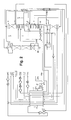
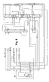
- a first feed air stream 1 is compressed in a first air compressor 2 with aftercooler 3 to approximately the operating pressure of the high-pressure column described below (plus line losses).
- the first air stream 4 then branches into a direct air stream 5 and a turbine air stream 6.
- the direct air 5 is fed directly to the warm end of a main heat exchanger 7 and is cooled there to approximately dew point.
- the cooled direct air 8 flows to the high-pressure column 9 without any further pressure-changing measures.
- the high-pressure column 9 is part of a rectification system for nitrogen-oxygen separation, which also comprises a medium-pressure column 10 and a low-pressure column 11. Their operating pressures are (each at the head): High-pressure column owing 14.5 to 17 bar, for example about 15 bar Medium pressure column owing 5 to 6 bar, for example about 5.5 bar Low pressure column owing 1.2 to 1.5 bar, for example about 1.3 bar
- the columns stand between the high pressure column via a first main condenser 12 and medium pressure column or a second main condenser 13 between Medium pressure column and low pressure column in a heat-exchanging connection.
- Main condensers are head gas of the respective lower column in a known manner indirect heat exchange with evaporating sump liquid of the respective upper one Column condensed.
- the turbine air flow 6, 16 is in a post-compressor 14 with an after-cooler 15 post-compressed, cooled to an intermediate temperature in the main heat exchanger 7 and via line 17 of work relaxation in a relaxation machine (Blowing turbine) 18, which is mechanically coupled to the post-compressor 14 is.
- the relaxed turbine air 19 is finally fed directly into the low pressure column 11 blown.
- the embodiment relates to an application in which limited Amount of air is already available under a superatmospheric pressure, for example, the medium pressure column pressure (plus line losses).
- a superatmospheric pressure for example, the medium pressure column pressure (plus line losses).
- Air flow - for example from a gas turbine-driven compressor or from other source - flows in the exemplary embodiment as a second feed air stream 20 towards the warm end of the main heat exchanger there will be about dew point cooled and finally fed directly to the medium pressure column 10.
- Oxygenated liquid 22 is discharged from the sump of the high pressure column 9 withdrawn, cooled in a first subcooling countercurrent 23, via line 24 and throttle valve 25 inserted into the medium pressure column and there for the first part subjected to a further countercurrent rectification. To another part 26 he becomes passed through a second supercooling counterflow 27.
- the hypothermic oxygen-enriched liquid 28 at intermediate pressure branches into two parts 29, 31, one of which is throttled via valve 30 into the low-pressure column 11.
- On Part 33 of the gaseous top nitrogen of the high pressure column 9 is in the Main heat exchanger 7 warmed to about ambient temperature and below that High pressure column pressure obtained as product 34 (GAN).
- Some of the nitrogen obtained in the first main condenser 12 is subcooled 35 (23) and given as return 36 on the head of the medium pressure column 10. Moreover generates the second main condenser 13 return 37 for the medium pressure column, as well if necessary liquid nitrogen product 38.
- An oxygen with a purity of about 99.5 is obtained from the bottom of the medium pressure column mol% withdrawn liquid and introduced into a secondary condenser 40. There he is in indirect heat exchange with condensing top nitrogen 41 the High pressure column 9 partially evaporated. A first, somewhat impure oxygen product 42, 43 becomes from the steam formed under approximately the medium pressure column pressure won (GOX), possibly after compression in the second stage 44 one Oxygen compressor 56/44 with after-cooling 45. From the in the secondary condenser 40 portion 46 remaining in liquid form becomes a purer high-pressure oxygen product by means of internal compression 49 (GOX-IC) generated.
- GOX-IC internal compression 49
- the liquid 46 by means of a Pump 47 brought to a corresponding pressure, via a liquid line 48 led to the cold end of the main heat exchanger and evaporated there and warmed up.
- a portion 82 of the gaseous nitrogen from the top of the medium pressure column becomes warmed in the main heat exchanger 7 and can via line 83 or - as shown -
- line 86 after compression in a nitrogen compressor 84 with Post-compressor 85 can be obtained as a printed product (PGAN).
- Return liquid 50, 51 for the head of the low pressure column 11 is from a Intermediate point of the medium pressure column 10 above the feed 24/25 oxygen-enriched liquid removed.
- impure nitrogen 52 is removed as residual gas and after heating 27-23-7 removed from the system via line 53 (UN2).
- the bottom product 54 of the Low-pressure column 11 is partially withdrawn in gaseous form, after heating 27-23-7 via line 55 of the first stage 56 (with intermediate cooling 57) of the Oxygen compressor 56/44 brought to about medium pressure column pressure and finally mixed with the medium pressure column oxygen 43. It can also be more fluid Oxygen 58 as a product or for flushing from the low pressure column sump subtracted from.
- a first argon-enriched stream 59 is gaseous from an intermediate point in the Subtracted medium pressure column 10, the 24/25 below the feed oxygen-enriched liquid and below the air supply via line 21 is arranged.
- the stream 59 is at least in a condenser-evaporator 60 partially, preferably completely condensed and finally via line 61 and Throttle valve 62 is introduced into a crude argon column 63, which is under approximately the same pressure how the low pressure column 11 is operated.
- the entry point of the first argon-enriched electricity is, for example, 30 to 40 theoretical plates, preferably 33 to 38 theoretical plates above the swamp at one Total number of 70 to 90 theoretical plates, preferably 78 to 85 theoretical plates Soils in the crude argon column 63.
- the condenser-evaporator 60 simultaneously represents the Bottom reboiler of the crude argon column 63.
- Part 65 of the non-evaporated Bottom liquid 64 of the crude argon column 63 is opened again in a pump 65 Brought medium pressure column pressure and returned to the medium pressure column 10 (66).
- the Rest 67 is introduced into the low pressure column 11.
- Another use is a second argon-enriched stream 68 in gaseous form from the Low pressure column 11 of the crude argon column fed directly to the sump.
- the top condenser 69 of the crude argon column 63 is enriched with oxygen Liquid 31 operated in a valve to a suitable pressure (about the same Low pressure column pressure) was released. Vapor formed in the top condenser 69 70 is introduced into the low pressure column at a suitable point.
- the raw argon product (the "argon-rich fraction") 75 becomes gaseous from the top of the crude argon column 63 or withdrawn from the liquefaction space of the top condenser 69.
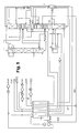
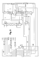
- the first argon-enriched stream 259 is warmed to an intermediate temperature in the main heat exchanger 7, passed to a relaxation machine 272 via line 271, where it is relieved of work to about 0.2 bar above crude argon column pressure and finally led into the evaporation space of the condenser-evaporator 60 (274 ).
- the expansion machine 272 is preferably designed as a turbine and coupled to a braking device 273, preferably a generator.
- FIG. 3 largely corresponds to FIG. 2, but here a sump reboiler for the crude argon column 63 is dispensed with and the first argon-enriched stream 374, which is relaxed during the work, is introduced in gaseous form into the sump of the crude argon column.
- the argon transfer turbine (272 in FIG. 2) is also dispensed with and the first argon-enriched stream 459 is throttled directly into the bottom of the crude argon column 63 (462).
- FIGS. 5 to 9 show alternatives to the blowing in of FIG Turbine air 19 in the low pressure column. These different methods of Refrigeration can also be combined with any of the methods of Figures 2 to 4 become.
- the air turbine 518 only relaxes to approximately the operating pressure of the medium pressure column 10. This variant is therefore particularly suitable when the cooling requirement is relatively low and increases the oxygen yield of the process.
- the air 519 which has been relieved of work is fed into the medium-pressure column 10 together with the second feed air stream 20-21 via line 521.
- FIG. 6 relates to a modification of FIG. 5, in which the turbine air 6 upstream of the turbine-driven post-compressor 14 is compressed in a further post-compressor 681 driven by external energy with post-cooling 682.
- a higher pressure ratio can be achieved on the turbine 518 and thus produce more cold.
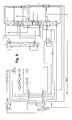
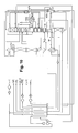
- process cold can be obtained in a nitrogen turbine 718 according to FIG. 7 .
- part 787 of the nitrogen 33 drawn off from the high-pressure column 9 is only heated to an intermediate temperature in the main heat exchanger 7 and expanded to approximately medium-pressure column pressure in a work-performing manner (718).
- the expanded high-pressure column nitrogen is finally combined with the medium-pressure column nitrogen 82 upstream of the main heat exchanger 7.
- the nitrogen turbine 718 is not coupled to a generator or to an oil brake as in FIG. 7, but is braked by means of a post-compressor 814, which increases the pressure in the turbine stream 887 and thus the inlet pressure of the turbine 718.
- the corresponding part 887 of the high-pressure column nitrogen is previously warmed to approximately ambient temperature and cooled downstream of the post-compressor 814 by means of an after-cooler 815.
- part 988 of the gaseous nitrogen 82 is made from the Medium pressure column 10 relaxed from an intermediate temperature from work.
- the Relaxation machine is, for example, by an oil brake or a Generator braked.
- the expanded nitrogen gas 989 is practically depressurized and will withdrawn below ambient temperature via line 990 (GAN).
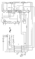
- FIG. 10 is based on FIG. 1, but shows a changed routing of the oxygen product from the low-pressure column 11.
- the entire bottom product is removed from the low-pressure column in liquid form (line 1076).
- the part that is not discharged via line 1058 as a liquid oxygen product or rinsing liquid flows through line 1077 to a pump 1078 and is brought to approximately medium-pressure column pressure there.
- the pumped low-pressure column oxygen 1079 is warmed in the first supercooling countercurrent 27 and finally introduced into the medium-pressure column 10 via line 1080.
- Line 39 now conveys all of the oxygen to be obtained in gaseous form, which was produced in medium pressure column 10 and low pressure column 11. This "pumping back" of the low-pressure column oxygen into the medium-pressure column can be applied in an analogous manner to the exemplary embodiments in FIGS. 2 to 9 and their variants.
- the exemplary embodiments show a rectification system for nitrogen-oxygen separation, which is designed as a triple column in the narrower sense, that is High pressure column, medium pressure column and low pressure column are arranged one above the other and are in pairs over a main condenser 12, 13 in heat exchangers Connection.
- the invention is also applicable to any other 3-pillar system applicable.
- the medium pressure column next to a classic Linde double column be arranged, which comprises high pressure column and low pressure column; alternatively, all three pillars could be arranged side by side.
- Others too Condenser configurations for the low pressure column, the medium pressure column and for the High pressure columns can be used in the context of the invention.
Landscapes
- Engineering & Computer Science (AREA)
- Physics & Mathematics (AREA)
- Mechanical Engineering (AREA)
- Thermal Sciences (AREA)
- General Engineering & Computer Science (AREA)
- Health & Medical Sciences (AREA)
- Emergency Medicine (AREA)
- Separation By Low-Temperature Treatments (AREA)
Abstract
Description
- Figur 1
- ein erstes Ausführungsbeispiel der Erfindung mit Sumpfheizung der Rohargonsäule mit der Argonübergangs-Fraktion aus der Mitteldrucksäule,
- Figur 2
- ein zweites Verfahren, bei dem die Argonübergangs-Fraktion aus der Mitteldrucksäule außerdem arbeitsleistend entspannt wird,
- Figur 3
- ein drittes Beispiel ohne Sumpfheizung der Rohargonsäule,
- Figur 4
- ein Verfahren mit direkter Einleitung der Argonübergangs-Fraktion aus der Mitteldrucksäule in die Rohargonsäule,
- Figuren 5 bis 9
- verschiedene Varianten der Kältegewinnung bei einem Verfahren der Figur 1 (auch auf die Verfahren der Figuren 2 bis 4 anwendbar) und
- Figur 10
- ein Prozess mit Zurückpumpen von Sauerstoff aus der Niederdrucksäule in die Mitteldrucksäule.
| Hochdrucksäule..... | 14,5 bis 17 bar, beispielsweise etwa 15 bar |
| Mitteldrucksäule ..... | 5 bis 6 bar, beispielsweise etwa 5,5 bar |
| Niederdrucksäule ..... | 1,2 bis 1,5 bar, beispielsweise etwa 1,3 bar |
Claims (7)
- Verfahren zur Tieftemperatur-Luftzerlegung von Luft in einem Rektifiziersystem zur Stickstoff-Sauerstoff-Trennung, das eine Hochdrucksäule (9), eine Niederdrucksäule (11) und eine Mitteldrucksäule (10) aufweist, und in einer Rohargonsäule (63), wobei bei dem Verfahrendadurch gekennzeichnet, dass(a)mindestens ein Einsatzluftstrom in das Rektifiziersystem zur Stickstoff-Sauerstoff-Trennung eingeleitet (8, 19, 21, 521) wird,(b)der Niederdrucksäule (11) mindestens ein Sauerstoff- oder Stickstoff-Produktstrom (52, 54, 58, 1076) entnommen wird,(c) mindestens ein erster argonangereicherter Strom (59, 61, 259, 271, 274, 276, 374) aus dem Rektifiziersystem zur Stickstoff-Sauerstoff-Trennung entnommen und der Rohargonsäule (63) zugeleitet wird und bei dem(d)der Rohargonsäule (63) eine argonreiche Fraktion 75 entnommen wird, deren Argongehalt größer als derjenige des ersten argonangereicherten Stroms (59, 61, 259, 271, 274, 276, 374) ist,(e)der erste argonangereicherte Strom (59, 61, 259, 271, 274, 276, 374) aus der Mitteldrucksäule (10) entnommen wird.
- Verfahren nach Anspruch 1, dadurch gekennzeichnet, dass ein zweiter argonangereicherter Strom (68) aus der Niederdrucksäule abgezogen und in die Rohargonsäule (63) eingeleitet wird.
- Verfahren nach Anspruch 1 oder 5, dadurch gekennzeichnet, dass die Sumpfflüssigkeit (64) der Rohargonsäule (63) mindestens teilweise in die Mitteldrucksäule (10) zurückgeführt (65, 66) wird.
- Verfahren nach einem der Ansprüche 1 bis 3, dadurch gekennzeichnet, dass mindestens ein Teil des ersten argonangereicherten Stroms (59, 274) stromaufwärts der Einleitung (61, 276) in die Rohargonsäule (63) in einem Kondensator-Verdampfer (60) mindestens teilweise kondensiert wird.
- Verfahren nach Anspruch 4, dadurch gekennzeichnet, dass in dem Kondensator-Verdampfer (60) ein Teil einer Flüssigkeit, insbesondere der Sumpfflüssigkeit, aus der Rohargonsäule (63) verdampft wird.
- Verfahren nach einem der Ansprüche 1 bis 5, dadurch gekennzeichnet, dass mindestens ein Teil des ersten argonangereicherten Stroms (259, 271) stromaufwärts der Einleitung (276, 374) in die Rohargonsäule (63) arbeitsleistend entspannt (272) wird.
- Vorrichtung zur Tieftemperatur-Luftzerlegung von Luft mit einem Rektifiziersystem zur Stickstoff-Sauerstoff-Trennung, das eine Hochdrucksäule (9), eine Niederdrucksäule (11) und eine Mitteldrucksäule (10) aufweist, mit einer Rohargonsäule (63) und mitdadurch gekennzeichnet, dass(a)mindestens einer Einsatzluftleitung (8, 19, 21, 521) zum Einleiten mindestens eines Einsatzluftstroms in das Rektifiziersystem zur Stickstoff-Sauerstoff-Trennung wird,(b)mindestens einer Produktleitung (52, 54, 58, 1076) zum Entnehmen mindestens eines Sauerstoff- oder Stickstoff-Produktstroms aus der Niederdrucksäule (11),(c) einer ersten Argonübergangs-Leitung (59, 61, 259, 271, 274, 276, 374) zur Einleitung eines argonangereicherten Stroms aus dem Rektifiziersystem zur Stickstoff-Sauerstoff-Trennung in die Rohargonsäule (63) und mit(d)einer Rohargon-Produktleitung (75) zum Entnehmen einer argonreichen Fraktion, deren Argongehalt größer als derjenige des ersten argonangereicherten Stroms ist, aus der Rohargonsäule (63),(e)die erste Argonübergangs-Leitung (59, 61, 259, 271, 274, 276, 374) mit der Mitteldrucksäule (10) verbunden ist.
Applications Claiming Priority (2)
| Application Number | Priority Date | Filing Date | Title |
|---|---|---|---|
| DE10217091 | 2002-04-17 | ||
| DE10217091A DE10217091A1 (de) | 2002-04-17 | 2002-04-17 | Drei-Säulen-System zur Tieftemperatur-Luftzerlegung mit Argongewinnung |
Publications (2)
| Publication Number | Publication Date |
|---|---|
| EP1357342A1 true EP1357342A1 (de) | 2003-10-29 |
| EP1357342B1 EP1357342B1 (de) | 2006-11-02 |
Family
ID=28685145
Family Applications (1)
| Application Number | Title | Priority Date | Filing Date |
|---|---|---|---|
| EP02011458A Expired - Lifetime EP1357342B1 (de) | 2002-04-17 | 2002-05-24 | Drei-Säulen-System zur Tieftemperaturzerlegung mit Argongewinnung |
Country Status (3)
| Country | Link |
|---|---|
| EP (1) | EP1357342B1 (de) |
| AT (1) | ATE344428T1 (de) |
| DE (2) | DE10217091A1 (de) |
Cited By (24)
| Publication number | Priority date | Publication date | Assignee | Title |
|---|---|---|---|---|
| DE102007031765A1 (de) | 2007-07-07 | 2009-01-08 | Linde Ag | Verfahren zur Tieftemperaturzerlegung von Luft |
| DE102007031759A1 (de) | 2007-07-07 | 2009-01-08 | Linde Ag | Verfahren und Vorrichtung zur Erzeugung von gasförmigem Druckprodukt durch Tieftemperaturzerlegung von Luft |
| DE102009034979A1 (de) | 2009-04-28 | 2010-11-04 | Linde Aktiengesellschaft | Verfahren und Vorrichtung zur Erzeugung von gasförmigem Drucksauerstoff |
| EP2312248A1 (de) | 2009-10-07 | 2011-04-20 | Linde Aktiengesellschaft | Verfahren und Vorrichtung Gewinnung von Drucksauerstoff und Krypton/Xenon |
| EP2458311A1 (de) | 2010-11-25 | 2012-05-30 | Linde Aktiengesellschaft | Verfahren und Vorrichtung zur Gewinnung eines gasförmigen Druckprodukts durch Tieftemperaturzerlegung von Luft |
| DE102010052544A1 (de) | 2010-11-25 | 2012-05-31 | Linde Ag | Verfahren zur Gewinnung eines gasförmigen Druckprodukts durch Tieftemperaturzerlegung von Luft |
| EP2520886A1 (de) | 2011-05-05 | 2012-11-07 | Linde AG | Verfahren und Vorrichtung zur Erzeugung eines gasförmigen Sauerstoff-Druckprodukts durch Tieftemperaturzerlegung von Luft |
| EP2568242A1 (de) | 2011-09-08 | 2013-03-13 | Linde Aktiengesellschaft | Verfahren und Vorrichtung zur Gewinnung von Stahl |
| EP2600090A1 (de) | 2011-12-01 | 2013-06-05 | Linde Aktiengesellschaft | Verfahren und Vorrichtung zur Erzeugung von Drucksauerstoff durch Tieftemperaturzerlegung von Luft |
| DE102011121314A1 (de) | 2011-12-16 | 2013-06-20 | Linde Aktiengesellschaft | Verfahren zur Erzeugung eines gasförmigen Sauerstoff-Druckprodukts durch Tieftemperaturzerlegung von Luft |
| US20130340476A1 (en) * | 2011-03-18 | 2013-12-26 | L'air Liquide Societe Anonyme Pour I'etude Et I'exploitation Des Procedes Georges Claude | Apparatus and method for separating air by cryogenic distillation |
| DE102013017590A1 (de) | 2013-10-22 | 2014-01-02 | Linde Aktiengesellschaft | Verfahren zur Gewinnung eines Krypton und Xenon enthaltenden Fluids und hierfür eingerichtete Luftzerlegungsanlage |
| DE102012017488A1 (de) | 2012-09-04 | 2014-03-06 | Linde Aktiengesellschaft | Verfahren zur Erstellung einer Luftzerlegungsanlage, Luftzerlegungsanlage und zugehöriges Betriebsverfahren |
| EP2784420A1 (de) | 2013-03-26 | 2014-10-01 | Linde Aktiengesellschaft | Verfahren zur Luftzerlegung und Luftzerlegungsanlage |
| WO2014154339A2 (de) | 2013-03-26 | 2014-10-02 | Linde Aktiengesellschaft | Verfahren zur luftzerlegung und luftzerlegungsanlage |
| EP2801777A1 (de) | 2013-05-08 | 2014-11-12 | Linde Aktiengesellschaft | Luftzerlegungsanlage mit Hauptverdichterantrieb |
| EP2963367A1 (de) | 2014-07-05 | 2016-01-06 | Linde Aktiengesellschaft | Verfahren und Vorrichtung zur Tieftemperaturzerlegung von Luft mit variablem Energieverbrauch |
| EP2963369A1 (de) | 2014-07-05 | 2016-01-06 | Linde Aktiengesellschaft | Verfahren und vorrichtung zur tieftemperaturzerlegung von luft |
| EP2963370A1 (de) | 2014-07-05 | 2016-01-06 | Linde Aktiengesellschaft | Verfahren und vorrichtung zur tieftemperaturzerlegung von luft |
| EP2963371A1 (de) | 2014-07-05 | 2016-01-06 | Linde Aktiengesellschaft | Verfahren und vorrichtung zur gewinnung eines druckgasprodukts durch tieftemperaturzerlegung von luft |
| CN105637311A (zh) * | 2013-10-15 | 2016-06-01 | 乔治洛德方法研究和开发液化空气有限公司 | 通过低温蒸馏分离空气的方法和装置 |
| WO2018114052A2 (de) | 2016-12-23 | 2018-06-28 | Linde Aktiengesellschaft | Verfahren zur tieftemperaturzerlegung von luft und luftzerlegungsanlage |
| US10852061B2 (en) | 2017-05-16 | 2020-12-01 | Terrence J. Ebert | Apparatus and process for liquefying gases |
| EP3913310A1 (de) | 2020-05-20 | 2021-11-24 | L'air Liquide, Societe Anonyme Pour L'etude Et L'exploitation Des Procedes Georges Claude | Verfahren und gerät zur trennung von luft durch kryogene destillation |
Families Citing this family (2)
| Publication number | Priority date | Publication date | Assignee | Title |
|---|---|---|---|---|
| DE102009023900A1 (de) | 2009-06-04 | 2010-12-09 | Linde Aktiengesellschaft | Dreisäulenverfahren und -vorrichtung zur Tieftemperaturzerlegung von Luft |
| JP6440232B1 (ja) * | 2018-03-20 | 2018-12-19 | レール・リキード−ソシエテ・アノニム・プール・レテュード・エ・レクスプロワタシオン・デ・プロセデ・ジョルジュ・クロード | 製品窒素ガスおよび製品アルゴンの製造方法およびその製造装置 |
Citations (7)
| Publication number | Priority date | Publication date | Assignee | Title |
|---|---|---|---|---|
| US4604116A (en) * | 1982-09-13 | 1986-08-05 | Erickson Donald C | High pressure oxygen pumped LOX rectifier |
| EP0446004A1 (de) * | 1990-03-06 | 1991-09-11 | Air Products And Chemicals, Inc. | Herstellung von ultrahochreinem Sauerstoff bei der Tieftemperatur-Luftzerlegung |
| EP0527501A1 (de) * | 1991-08-14 | 1993-02-17 | Linde Aktiengesellschaft | Verfahren und Vorrichtung zur Luftzerlegung durch Rektifikation |
| EP0594214A1 (de) * | 1992-10-23 | 1994-04-27 | Praxair Technology, Inc. | Kryogenisches Rektifikationsverfahren mit thermisch integrierter Argonkolonne |
| EP0687876A1 (de) * | 1994-06-17 | 1995-12-20 | The BOC Group plc | Lufttrennung |
| DE19609490A1 (de) * | 1995-03-10 | 1996-09-12 | Linde Ag | Verfahren und Vorrichtung zur Tieftemperaturzerlegung von Luft |
| EP0831285A2 (de) * | 1996-09-20 | 1998-03-25 | The BOC Group plc | Lufttrennung |
-
2002
- 2002-04-17 DE DE10217091A patent/DE10217091A1/de not_active Withdrawn
- 2002-05-24 DE DE50208594T patent/DE50208594D1/de not_active Expired - Lifetime
- 2002-05-24 EP EP02011458A patent/EP1357342B1/de not_active Expired - Lifetime
- 2002-05-24 AT AT02011458T patent/ATE344428T1/de not_active IP Right Cessation
Patent Citations (7)
| Publication number | Priority date | Publication date | Assignee | Title |
|---|---|---|---|---|
| US4604116A (en) * | 1982-09-13 | 1986-08-05 | Erickson Donald C | High pressure oxygen pumped LOX rectifier |
| EP0446004A1 (de) * | 1990-03-06 | 1991-09-11 | Air Products And Chemicals, Inc. | Herstellung von ultrahochreinem Sauerstoff bei der Tieftemperatur-Luftzerlegung |
| EP0527501A1 (de) * | 1991-08-14 | 1993-02-17 | Linde Aktiengesellschaft | Verfahren und Vorrichtung zur Luftzerlegung durch Rektifikation |
| EP0594214A1 (de) * | 1992-10-23 | 1994-04-27 | Praxair Technology, Inc. | Kryogenisches Rektifikationsverfahren mit thermisch integrierter Argonkolonne |
| EP0687876A1 (de) * | 1994-06-17 | 1995-12-20 | The BOC Group plc | Lufttrennung |
| DE19609490A1 (de) * | 1995-03-10 | 1996-09-12 | Linde Ag | Verfahren und Vorrichtung zur Tieftemperaturzerlegung von Luft |
| EP0831285A2 (de) * | 1996-09-20 | 1998-03-25 | The BOC Group plc | Lufttrennung |
Cited By (33)
| Publication number | Priority date | Publication date | Assignee | Title |
|---|---|---|---|---|
| DE102007031765A1 (de) | 2007-07-07 | 2009-01-08 | Linde Ag | Verfahren zur Tieftemperaturzerlegung von Luft |
| DE102007031759A1 (de) | 2007-07-07 | 2009-01-08 | Linde Ag | Verfahren und Vorrichtung zur Erzeugung von gasförmigem Druckprodukt durch Tieftemperaturzerlegung von Luft |
| EP2015013A2 (de) | 2007-07-07 | 2009-01-14 | Linde Aktiengesellschaft | Verfahren und Vorrichtung zur Erzeugung von gasförmigem Druckprodukt durch Tieftemperaturzerlegung von Luft |
| EP2015012A2 (de) | 2007-07-07 | 2009-01-14 | Linde Aktiengesellschaft | Verfahren zur Tieftemperaturzerlegung von Luft |
| DE102009034979A1 (de) | 2009-04-28 | 2010-11-04 | Linde Aktiengesellschaft | Verfahren und Vorrichtung zur Erzeugung von gasförmigem Drucksauerstoff |
| EP2312248A1 (de) | 2009-10-07 | 2011-04-20 | Linde Aktiengesellschaft | Verfahren und Vorrichtung Gewinnung von Drucksauerstoff und Krypton/Xenon |
| EP2458311A1 (de) | 2010-11-25 | 2012-05-30 | Linde Aktiengesellschaft | Verfahren und Vorrichtung zur Gewinnung eines gasförmigen Druckprodukts durch Tieftemperaturzerlegung von Luft |
| DE102010052545A1 (de) | 2010-11-25 | 2012-05-31 | Linde Aktiengesellschaft | Verfahren und Vorrichtung zur Gewinnung eines gasförmigen Druckprodukts durch Tieftemperaturzerlegung von Luft |
| DE102010052544A1 (de) | 2010-11-25 | 2012-05-31 | Linde Ag | Verfahren zur Gewinnung eines gasförmigen Druckprodukts durch Tieftemperaturzerlegung von Luft |
| EP2466236A1 (de) | 2010-11-25 | 2012-06-20 | Linde Aktiengesellschaft | Verfahren zur Gewinnung eines gasförmigen Druckprodukts durch Tiefemperaturzerlegung von Luft |
| US20130340476A1 (en) * | 2011-03-18 | 2013-12-26 | L'air Liquide Societe Anonyme Pour I'etude Et I'exploitation Des Procedes Georges Claude | Apparatus and method for separating air by cryogenic distillation |
| EP2520886A1 (de) | 2011-05-05 | 2012-11-07 | Linde AG | Verfahren und Vorrichtung zur Erzeugung eines gasförmigen Sauerstoff-Druckprodukts durch Tieftemperaturzerlegung von Luft |
| EP2568242A1 (de) | 2011-09-08 | 2013-03-13 | Linde Aktiengesellschaft | Verfahren und Vorrichtung zur Gewinnung von Stahl |
| DE102011112909A1 (de) | 2011-09-08 | 2013-03-14 | Linde Aktiengesellschaft | Verfahren und Vorrichtung zur Gewinnung von Stahl |
| EP2600090A1 (de) | 2011-12-01 | 2013-06-05 | Linde Aktiengesellschaft | Verfahren und Vorrichtung zur Erzeugung von Drucksauerstoff durch Tieftemperaturzerlegung von Luft |
| DE102011121314A1 (de) | 2011-12-16 | 2013-06-20 | Linde Aktiengesellschaft | Verfahren zur Erzeugung eines gasförmigen Sauerstoff-Druckprodukts durch Tieftemperaturzerlegung von Luft |
| DE102012017488A1 (de) | 2012-09-04 | 2014-03-06 | Linde Aktiengesellschaft | Verfahren zur Erstellung einer Luftzerlegungsanlage, Luftzerlegungsanlage und zugehöriges Betriebsverfahren |
| EP2784420A1 (de) | 2013-03-26 | 2014-10-01 | Linde Aktiengesellschaft | Verfahren zur Luftzerlegung und Luftzerlegungsanlage |
| WO2014154339A2 (de) | 2013-03-26 | 2014-10-02 | Linde Aktiengesellschaft | Verfahren zur luftzerlegung und luftzerlegungsanlage |
| EP2801777A1 (de) | 2013-05-08 | 2014-11-12 | Linde Aktiengesellschaft | Luftzerlegungsanlage mit Hauptverdichterantrieb |
| CN105637311A (zh) * | 2013-10-15 | 2016-06-01 | 乔治洛德方法研究和开发液化空气有限公司 | 通过低温蒸馏分离空气的方法和装置 |
| CN105637311B (zh) * | 2013-10-15 | 2018-06-29 | 乔治洛德方法研究和开发液化空气有限公司 | 通过低温蒸馏分离空气的方法和装置 |
| DE102013017590A1 (de) | 2013-10-22 | 2014-01-02 | Linde Aktiengesellschaft | Verfahren zur Gewinnung eines Krypton und Xenon enthaltenden Fluids und hierfür eingerichtete Luftzerlegungsanlage |
| EP2963370A1 (de) | 2014-07-05 | 2016-01-06 | Linde Aktiengesellschaft | Verfahren und vorrichtung zur tieftemperaturzerlegung von luft |
| EP2963371A1 (de) | 2014-07-05 | 2016-01-06 | Linde Aktiengesellschaft | Verfahren und vorrichtung zur gewinnung eines druckgasprodukts durch tieftemperaturzerlegung von luft |
| WO2016005031A1 (de) | 2014-07-05 | 2016-01-14 | Linde Aktiengesellschaft | Verfahren und vorrichtung zur tieftemperaturzerlegung von luft mit variablem energieverbrauch |
| EP2963369A1 (de) | 2014-07-05 | 2016-01-06 | Linde Aktiengesellschaft | Verfahren und vorrichtung zur tieftemperaturzerlegung von luft |
| EP2963367A1 (de) | 2014-07-05 | 2016-01-06 | Linde Aktiengesellschaft | Verfahren und Vorrichtung zur Tieftemperaturzerlegung von Luft mit variablem Energieverbrauch |
| WO2018114052A2 (de) | 2016-12-23 | 2018-06-28 | Linde Aktiengesellschaft | Verfahren zur tieftemperaturzerlegung von luft und luftzerlegungsanlage |
| WO2018114052A3 (de) * | 2016-12-23 | 2018-10-11 | Linde Aktiengesellschaft | Verfahren zur tieftemperaturzerlegung von luft und luftzerlegungsanlage |
| US10852061B2 (en) | 2017-05-16 | 2020-12-01 | Terrence J. Ebert | Apparatus and process for liquefying gases |
| EP3913310A1 (de) | 2020-05-20 | 2021-11-24 | L'air Liquide, Societe Anonyme Pour L'etude Et L'exploitation Des Procedes Georges Claude | Verfahren und gerät zur trennung von luft durch kryogene destillation |
| FR3110685A1 (fr) * | 2020-05-20 | 2021-11-26 | L'air Liquide, Societe Anonyme Pour L'etude Et L'exploitation Des Procedes Georges Claude | Procédé et appareil de séparation d’air par distillation cryogénique |
Also Published As
| Publication number | Publication date |
|---|---|
| DE10217091A1 (de) | 2003-11-06 |
| EP1357342B1 (de) | 2006-11-02 |
| DE50208594D1 (de) | 2006-12-14 |
| ATE344428T1 (de) | 2006-11-15 |
Similar Documents
| Publication | Publication Date | Title |
|---|---|---|
| EP2235460B1 (de) | Verfahren und vorrichtung zur tieftemperatur-luftzerlegung | |
| EP1357342B1 (de) | Drei-Säulen-System zur Tieftemperaturzerlegung mit Argongewinnung | |
| EP1243882B1 (de) | Argongewinnung mit einem Drei-Säulen-System zur Luftzerlegung und einer Rohargonsäule | |
| EP2236964B1 (de) | Verfahren und Vorrichtung zur Tieftemperatur-Luftzerlegung | |
| EP1482266B1 (de) | Verfahren und Vorrichtung zur Gewinnung von Krypton und/oder Xenon durch Tieftemperaturzerlegung von Luft | |
| EP2015013A2 (de) | Verfahren und Vorrichtung zur Erzeugung von gasförmigem Druckprodukt durch Tieftemperaturzerlegung von Luft | |
| DE10153252A1 (de) | Verfahren und Vorrichtung zur Gewinnung von Krypton und/oder Xenon durch Tieftemperaturzerlegung von Luft | |
| EP1284404A1 (de) | Verfahren und Vorrichtung zur Gewinnung eines Druckprodukts durch Tieftemperaturzerlegung von Luft | |
| EP3290843A2 (de) | Verfahren und vorrichtung zur erzeugung von druckstickstoff und flüssigstickstoff durch tieftemperaturzerlegung von luft | |
| WO2020169257A1 (de) | Verfahren und anlage zur tieftemperaturzerlegung von luft | |
| DE10238282A1 (de) | Verfahren zur Tieftemperatur-Zerlegung von Luft | |
| DE19609490A1 (de) | Verfahren und Vorrichtung zur Tieftemperaturzerlegung von Luft | |
| WO2021078405A1 (de) | Verfahren und anlage zur tieftemperaturzerlegung von luft | |
| EP3980705A1 (de) | Verfahren und anlage zur tieftemperaturzerlegung von luft | |
| EP2551619A1 (de) | Verfahren und Vorrichtung zur Gewinnung von Druckstickstoff und Drucksauerstoff durch Tieftemperaturzerlegung von Luft | |
| DE19933558C5 (de) | Dreisäulenverfahren und -vorrichtung zur Tieftemperaturzerlegung von Luft | |
| EP4065910A1 (de) | Verfahren und anlage zur tieftemperaturzerlegung von luft | |
| WO2017108187A1 (de) | Verfahren und vorrichtung zur erzeugung von reinem stickstoff und reinem sauerstoff durch tieftemperaturzerlegung von luft | |
| EP1189001B1 (de) | Verfahren und Vorrichtung zur Erzeugung hoch reinen Stickstoffs durch Tieftemperatur-Luftzerlegung | |
| EP1199532A1 (de) | Drei-Säulen-System zur Tieftemperatur-Zerlegung von Luft | |
| DE10045121A1 (de) | Verfahren und Vorrichtung zur Gewinnung eines gasförmigen Produkts durch Tieftemperaturzerlegung von Luft | |
| DE10251485A1 (de) | Verfahren und Vorrichtung zur Argongewinnung durch Tieftemperaturzerlegung von Luft | |
| EP1284403B1 (de) | Verfahren und Vorrichtung zur Erzeugung von Sauerstoff durch Tieftemperatur-Zerlegung von Luft | |
| WO2020187449A1 (de) | Verfahren und anlage zur tieftemperaturzerlegung von luft | |
| EP1750074A1 (de) | Verfahren und Vorrichtung zur Tieftemperaturzerlegung von Luft |
Legal Events
| Date | Code | Title | Description |
|---|---|---|---|
| PUAI | Public reference made under article 153(3) epc to a published international application that has entered the european phase |
Free format text: ORIGINAL CODE: 0009012 |
|
| AK | Designated contracting states |
Kind code of ref document: A1 Designated state(s): AT BE CH CY DE DK ES FI FR GB GR IE IT LI LU MC NL PT SE TR |
|
| AX | Request for extension of the european patent |
Extension state: AL LT LV MK RO SI |
|
| 17P | Request for examination filed |
Effective date: 20040427 |
|
| AKX | Designation fees paid |
Designated state(s): AT BE CH CY DE DK ES FI FR GB GR IE IT LI LU MC NL PT SE TR |
|
| GRAP | Despatch of communication of intention to grant a patent |
Free format text: ORIGINAL CODE: EPIDOSNIGR1 |
|
| RIN1 | Information on inventor provided before grant (corrected) |
Inventor name: KUNZ, CHRISTIAN Inventor name: ROTTMANN, DIETRICH |
|
| GRAS | Grant fee paid |
Free format text: ORIGINAL CODE: EPIDOSNIGR3 |
|
| GRAA | (expected) grant |
Free format text: ORIGINAL CODE: 0009210 |
|
| AK | Designated contracting states |
Kind code of ref document: B1 Designated state(s): AT BE CH CY DE DK ES FI FR GB GR IE IT LI LU MC NL PT SE TR |
|
| PG25 | Lapsed in a contracting state [announced via postgrant information from national office to epo] |
Ref country code: IT Free format text: LAPSE BECAUSE OF FAILURE TO SUBMIT A TRANSLATION OF THE DESCRIPTION OR TO PAY THE FEE WITHIN THE PRESCRIBED TIME-LIMIT;WARNING: LAPSES OF ITALIAN PATENTS WITH EFFECTIVE DATE BEFORE 2007 MAY HAVE OCCURRED AT ANY TIME BEFORE 2007. THE CORRECT EFFECTIVE DATE MAY BE DIFFERENT FROM THE ONE RECORDED. Effective date: 20061102 Ref country code: FI Free format text: LAPSE BECAUSE OF FAILURE TO SUBMIT A TRANSLATION OF THE DESCRIPTION OR TO PAY THE FEE WITHIN THE PRESCRIBED TIME-LIMIT Effective date: 20061102 Ref country code: NL Free format text: LAPSE BECAUSE OF FAILURE TO SUBMIT A TRANSLATION OF THE DESCRIPTION OR TO PAY THE FEE WITHIN THE PRESCRIBED TIME-LIMIT Effective date: 20061102 Ref country code: IE Free format text: LAPSE BECAUSE OF FAILURE TO SUBMIT A TRANSLATION OF THE DESCRIPTION OR TO PAY THE FEE WITHIN THE PRESCRIBED TIME-LIMIT Effective date: 20061102 |
|
| REG | Reference to a national code |
Ref country code: GB Ref legal event code: FG4D Free format text: NOT ENGLISH |
|
| REG | Reference to a national code |
Ref country code: IE Ref legal event code: FG4D Free format text: LANGUAGE OF EP DOCUMENT: GERMAN |
|
| REG | Reference to a national code |
Ref country code: CH Ref legal event code: EP |
|
| REF | Corresponds to: |
Ref document number: 50208594 Country of ref document: DE Date of ref document: 20061214 Kind code of ref document: P |
|
| PG25 | Lapsed in a contracting state [announced via postgrant information from national office to epo] |
Ref country code: DK Free format text: LAPSE BECAUSE OF FAILURE TO SUBMIT A TRANSLATION OF THE DESCRIPTION OR TO PAY THE FEE WITHIN THE PRESCRIBED TIME-LIMIT Effective date: 20070202 Ref country code: SE Free format text: LAPSE BECAUSE OF FAILURE TO SUBMIT A TRANSLATION OF THE DESCRIPTION OR TO PAY THE FEE WITHIN THE PRESCRIBED TIME-LIMIT Effective date: 20070202 |
|
| PG25 | Lapsed in a contracting state [announced via postgrant information from national office to epo] |
Ref country code: ES Free format text: LAPSE BECAUSE OF FAILURE TO SUBMIT A TRANSLATION OF THE DESCRIPTION OR TO PAY THE FEE WITHIN THE PRESCRIBED TIME-LIMIT Effective date: 20070213 |
|
| PG25 | Lapsed in a contracting state [announced via postgrant information from national office to epo] |
Ref country code: PT Free format text: LAPSE BECAUSE OF FAILURE TO SUBMIT A TRANSLATION OF THE DESCRIPTION OR TO PAY THE FEE WITHIN THE PRESCRIBED TIME-LIMIT Effective date: 20070402 |
|
| NLV1 | Nl: lapsed or annulled due to failure to fulfill the requirements of art. 29p and 29m of the patents act | ||
| GBV | Gb: ep patent (uk) treated as always having been void in accordance with gb section 77(7)/1977 [no translation filed] |
Effective date: 20061102 |
|
| EN | Fr: translation not filed | ||
| REG | Reference to a national code |
Ref country code: IE Ref legal event code: FD4D |
|
| PLBE | No opposition filed within time limit |
Free format text: ORIGINAL CODE: 0009261 |
|
| STAA | Information on the status of an ep patent application or granted ep patent |
Free format text: STATUS: NO OPPOSITION FILED WITHIN TIME LIMIT |
|
| 26N | No opposition filed |
Effective date: 20070803 |
|
| PG25 | Lapsed in a contracting state [announced via postgrant information from national office to epo] |
Ref country code: GB Free format text: LAPSE BECAUSE OF FAILURE TO SUBMIT A TRANSLATION OF THE DESCRIPTION OR TO PAY THE FEE WITHIN THE PRESCRIBED TIME-LIMIT Effective date: 20061102 |
|
| BERE | Be: lapsed |
Owner name: LINDE A.G. Effective date: 20070531 |
|
| REG | Reference to a national code |
Ref country code: CH Ref legal event code: PL |
|
| PG25 | Lapsed in a contracting state [announced via postgrant information from national office to epo] |
Ref country code: MC Free format text: LAPSE BECAUSE OF NON-PAYMENT OF DUE FEES Effective date: 20070531 |
|
| PG25 | Lapsed in a contracting state [announced via postgrant information from national office to epo] |
Ref country code: CH Free format text: LAPSE BECAUSE OF NON-PAYMENT OF DUE FEES Effective date: 20070531 Ref country code: LI Free format text: LAPSE BECAUSE OF NON-PAYMENT OF DUE FEES Effective date: 20070531 |
|
| PG25 | Lapsed in a contracting state [announced via postgrant information from national office to epo] |
Ref country code: BE Free format text: LAPSE BECAUSE OF NON-PAYMENT OF DUE FEES Effective date: 20070531 |
|
| PG25 | Lapsed in a contracting state [announced via postgrant information from national office to epo] |
Ref country code: GR Free format text: LAPSE BECAUSE OF FAILURE TO SUBMIT A TRANSLATION OF THE DESCRIPTION OR TO PAY THE FEE WITHIN THE PRESCRIBED TIME-LIMIT Effective date: 20070203 Ref country code: FR Free format text: LAPSE BECAUSE OF FAILURE TO SUBMIT A TRANSLATION OF THE DESCRIPTION OR TO PAY THE FEE WITHIN THE PRESCRIBED TIME-LIMIT Effective date: 20070615 |
|
| PG25 | Lapsed in a contracting state [announced via postgrant information from national office to epo] |
Ref country code: AT Free format text: LAPSE BECAUSE OF NON-PAYMENT OF DUE FEES Effective date: 20070524 |
|
| PG25 | Lapsed in a contracting state [announced via postgrant information from national office to epo] |
Ref country code: FR Free format text: LAPSE BECAUSE OF FAILURE TO SUBMIT A TRANSLATION OF THE DESCRIPTION OR TO PAY THE FEE WITHIN THE PRESCRIBED TIME-LIMIT Effective date: 20061102 |
|
| PG25 | Lapsed in a contracting state [announced via postgrant information from national office to epo] |
Ref country code: CY Free format text: LAPSE BECAUSE OF FAILURE TO SUBMIT A TRANSLATION OF THE DESCRIPTION OR TO PAY THE FEE WITHIN THE PRESCRIBED TIME-LIMIT Effective date: 20061102 Ref country code: LU Free format text: LAPSE BECAUSE OF NON-PAYMENT OF DUE FEES Effective date: 20070524 |
|
| PG25 | Lapsed in a contracting state [announced via postgrant information from national office to epo] |
Ref country code: TR Free format text: LAPSE BECAUSE OF FAILURE TO SUBMIT A TRANSLATION OF THE DESCRIPTION OR TO PAY THE FEE WITHIN THE PRESCRIBED TIME-LIMIT Effective date: 20061102 |
|
| PGFP | Annual fee paid to national office [announced via postgrant information from national office to epo] |
Ref country code: DE Payment date: 20100519 Year of fee payment: 9 |
|
| REG | Reference to a national code |
Ref country code: DE Ref legal event code: R119 Ref document number: 50208594 Country of ref document: DE Effective date: 20111201 |
|
| PG25 | Lapsed in a contracting state [announced via postgrant information from national office to epo] |
Ref country code: DE Free format text: LAPSE BECAUSE OF NON-PAYMENT OF DUE FEES Effective date: 20111201 |