EP1359278A2 - Insulated sectional door and method of construction - Google Patents
Insulated sectional door and method of construction Download PDFInfo
- Publication number
- EP1359278A2 EP1359278A2 EP03252410A EP03252410A EP1359278A2 EP 1359278 A2 EP1359278 A2 EP 1359278A2 EP 03252410 A EP03252410 A EP 03252410A EP 03252410 A EP03252410 A EP 03252410A EP 1359278 A2 EP1359278 A2 EP 1359278A2
- Authority
- EP
- European Patent Office
- Prior art keywords
- sheet
- insulation material
- stiles
- rails
- door
- Prior art date
- Legal status (The legal status is an assumption and is not a legal conclusion. Google has not performed a legal analysis and makes no representation as to the accuracy of the status listed.)
- Withdrawn
Links
Images
Classifications
-
- E—FIXED CONSTRUCTIONS
- E06—DOORS, WINDOWS, SHUTTERS, OR ROLLER BLINDS IN GENERAL; LADDERS
- E06B—FIXED OR MOVABLE CLOSURES FOR OPENINGS IN BUILDINGS, VEHICLES, FENCES OR LIKE ENCLOSURES IN GENERAL, e.g. DOORS, WINDOWS, BLINDS, GATES
- E06B3/00—Window sashes, door leaves, or like elements for closing wall or like openings; Layout of fixed or moving closures, e.g. windows in wall or like openings; Features of rigidly-mounted outer frames relating to the mounting of wing frames
- E06B3/32—Arrangements of wings characterised by the manner of movement; Arrangements of movable wings in openings; Features of wings or frames relating solely to the manner of movement of the wing
- E06B3/48—Wings connected at their edges, e.g. foldable wings
- E06B3/485—Sectional doors
-
- E—FIXED CONSTRUCTIONS
- E06—DOORS, WINDOWS, SHUTTERS, OR ROLLER BLINDS IN GENERAL; LADDERS
- E06B—FIXED OR MOVABLE CLOSURES FOR OPENINGS IN BUILDINGS, VEHICLES, FENCES OR LIKE ENCLOSURES IN GENERAL, e.g. DOORS, WINDOWS, BLINDS, GATES
- E06B3/00—Window sashes, door leaves, or like elements for closing wall or like openings; Layout of fixed or moving closures, e.g. windows in wall or like openings; Features of rigidly-mounted outer frames relating to the mounting of wing frames
- E06B3/70—Door leaves
- E06B3/7015—Door leaves characterised by the filling between two external panels
- E06B2003/7023—Door leaves characterised by the filling between two external panels of foam type
-
- E—FIXED CONSTRUCTIONS
- E06—DOORS, WINDOWS, SHUTTERS, OR ROLLER BLINDS IN GENERAL; LADDERS
- E06B—FIXED OR MOVABLE CLOSURES FOR OPENINGS IN BUILDINGS, VEHICLES, FENCES OR LIKE ENCLOSURES IN GENERAL, e.g. DOORS, WINDOWS, BLINDS, GATES
- E06B3/00—Window sashes, door leaves, or like elements for closing wall or like openings; Layout of fixed or moving closures, e.g. windows in wall or like openings; Features of rigidly-mounted outer frames relating to the mounting of wing frames
- E06B3/70—Door leaves
- E06B2003/7044—Garage doors
-
- E—FIXED CONSTRUCTIONS
- E06—DOORS, WINDOWS, SHUTTERS, OR ROLLER BLINDS IN GENERAL; LADDERS
- E06B—FIXED OR MOVABLE CLOSURES FOR OPENINGS IN BUILDINGS, VEHICLES, FENCES OR LIKE ENCLOSURES IN GENERAL, e.g. DOORS, WINDOWS, BLINDS, GATES
- E06B3/00—Window sashes, door leaves, or like elements for closing wall or like openings; Layout of fixed or moving closures, e.g. windows in wall or like openings; Features of rigidly-mounted outer frames relating to the mounting of wing frames
- E06B3/70—Door leaves
- E06B3/7001—Coverings therefor; Door leaves imitating traditional raised panel doors, e.g. engraved or embossed surfaces, with trim strips applied to the surfaces
Definitions
- This invention relates to an insulated sectional door, such as a residential garage door, and its method of assembly. More specifically, this invention relates to such a door wherein the insulation is attached thereto without the need for gluing or the use of separate fasteners.
- the only known system which may allow the foam to be installed or changed on site provides a foam sheet with a backing material that is peripherally larger than the foam at the location of the rails of the panels.
- a further retention device such as glue is employed, thermal expansion and contraction of the foam and its backing will loosen the fit thereof to the point where the foam and backing could fall out of the door.
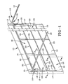
- a door made in accordance with the concepts of the present invention includes a plurality of panels, each of which includes opposed rails and a faceplate extending laterally between the rails.
- a sheet of insulation material has lateral edges positioned adjacent to the rails.
- a backing sheet is attached to the sheet of insulation material and has lateral edges which overhang the lateral edges of the insulation sheet such that the lateral edges of the backing sheet engage the rails to hold the insulation sheet against the faceplate.
- a sectional door panel includes a pair of spaced rails with at least two stiles extending between the rails.
- a faceplate is integral with and extends between the rails and overlies the stiles.
- An insulating sheet extends between the stiles and proximate the rails. Means associated with the insulating sheet are provided to engage the rails to maintain the insulating sheet pressed against the faceplate.
- a method of assembling a door having laterally spaced rails and a faceplate extending therebetween includes the steps of attaching a backing sheet to a sheet of insulation material, with the backing sheet having lateral edges overhanging the lateral edges of the sheet of insulation material, and engaging the rails with the lateral edges of the backing sheet to press the sheet of insulation material against the faceplate.
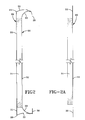
- backing sheet 32 extends beyond or otherwise overhangs the edges of insulation sheet 31, as at overhangs 33.
- backing sheet 32 need not be a separate element. Rather, the overhangs 33 could be formed as an extension of a portion of the insulation sheet 31 just so long as the overhangs 33 have sufficient strength and resilience to perform the functions hereinafter described.
- backing sheet 32 may be generally coincident with the edges of insulation sheet 31 as shown in Figs. 3 and 3A.
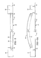
- the longitudinal dimension of insulation assembly 30 is greater than the distance between stiles 24 and 25 or adjacent stiles 25.
- insulation sheet 31 and backing sheet 32 must be deflected or bowed, as shown in Fig. 3A, so that the ends thereof will clear stiles 24 and 25.
- stiles 24 and 25 are provided with opposed relieved areas or notches 34 adjacent to faceplate 21, end stiles 24 having one such relieved area 34, and intermediate stiles 25 have two relieved areas 34.
- the door retailer or installer can stock several different insulation assemblies 30 to thereby create a door 10 with the insulation quality and thickness requested by the customer.
- the difference between these assemblies is that the insulation sheet 31 can be made thicker or thinner dependent on the amount of insulation desired. It has been found that the system described herein is readily operable using foam insulation sheets 31 in the range of approximately one-half inch thick to approximately one and one-half inches thick. It should be appreciated that as the foam insulation sheet 31 becomes thicker, shorter overhangs 33 are employed to fill rails 26 and 27 and engage surfaces 28 and 29.
- a door 10 constructed in accordance with the concepts of the present invention can readily be assembled in the field, or the insulation quality of an existing door can readily be changed. As such, door 10 accomplishes one or more of the objects of the invention and otherwise substantially improves the art.
Landscapes
- Engineering & Computer Science (AREA)
- Civil Engineering (AREA)
- Structural Engineering (AREA)
- Securing Of Glass Panes Or The Like (AREA)
Abstract
Description
Claims (20)
- A door comprising a plurality of panels, each said panel having opposed rails and a faceplate extending laterally between said rails, a sheet of insulation material having laterally spaced edges positioned adjacent to said rails, and a backing sheet attached to said sheet of insulation material and having lateral edges overhanging the lateral edges of said sheet of insulation material such that the lateral edges of said backing sheet engage said rails to hold said sheet of insulation material against said faceplate.
- The door according to claim 1 further comprising opposed stiles for each said panel, said faceplate extending longitudinally between said stiles.
- The door according to claim 2, each said stile having at least one notch to receive the longitudinal edges of said sheet of insulation material and said backing sheet.
- The door according to claim 3 wherein said opposed stiles are closer to each other than the longitudinal dimension of said sheet of insulation material such that said sheet of insulation material can be bowed for insertion between said stiles and straightens when said longitudinal edges are received in said notches.
- The door according to claim 1 wherein each said rail includes a return surface spaced from and generally parallel to said faceplate.
- The door according to claim 5 wherein the lateral edges of said backing sheet engage said return surfaces of said rails.
- The door according to claim 1 wherein said sheet of insulation material is a foam and said backing sheet is constructed of a relatively deformable material.
- The door according to claim 7 wherein said foam is of a thickness in the range of approximately one-half inch to approximately one and one-half inches.
- The door according to claim 8 wherein the length of the overhanging edges of said backing sheet is dependent on the thickness of said foam.
- A method of assembling a door having laterally spaced rails and a faceplate extending between the rails, comprising the steps of attaching a backing sheet to a sheet of insulation material with the backing sheet having lateral edges overhanging the sheet of insulation material, and engaging the rails with the lateral edges of the backing sheet to press the sheet of insulation material against the faceplate.
- The method of claim 10, the door having longitudinally spaced stiles with the faceplate extending between the stiles, further comprising the step of engaging the stiles with the longitudinal edges of the backing sheet.
- The method of claim 11 wherein the stiles include at least one notch and the step of engaging the stiles includes the step of positioning the longitudinal edges of the insulation material in the notches of opposed stiles.
- The method of claim 12 further comprising the step of engaging the stiles with the longitudinal edges of the insulation material thereby flexing the insulation material prior to positioning the insulation material in the notches.
- The method of claim 10 further comprising the step of decreasing the length of the overhang of the backing sheet when increasing the thickness of the insulation material.
- A method of installing an insulation material, having a backing sheet with a portion overhanging the lateral edges of the material, into a panel of a door having a faceplate with lateral edges defined by rails and longitudinal edges defined by stiles, comprising the steps of positioning the longitudinal edges of the insulation material adjacent to the stiles, and bringing the overhanging portion of the backing sheet into engagement with the rails to deform the overhanging portion thereby pressing the insulation material against the faceplate.
- The method of claim 15 wherein the stiles include at least one notch and the step of positioning the longitudinal edges of the insulation material adjacent to the stiles includes the step of positioning the longitudinal edges of the insulation material in the notches.
- The method of claim 16 wherein the step of positioning the longitudinal edges of the insulation material adjacent to the stiles includes the step of flexing the insulation material.
- A sectional door panel comprising a pair of spaced rails, at least two stiles extending between said rails, a faceplate integral with and extending between said rails and overlying said stiles, an insulating sheet extending between said stiles and proximate said rails, and means associated with said insulating sheet engaging said rails for maintaining said insulating sheet pressed against said faceplate.
- A door panel according to claim 18 wherein said means for maintaining said insulating sheet compressed against said faceplate is a backer of said insulating sheet.
- A door panel according to claim 18 wherein said stiles have notches for receiving and retaining said insulating sheet.
Applications Claiming Priority (2)
| Application Number | Priority Date | Filing Date | Title |
|---|---|---|---|
| US124516 | 2002-04-17 | ||
| US10/124,516 US6725898B2 (en) | 2002-04-17 | 2002-04-17 | Insulated sectional door and method of construction |
Publications (2)
| Publication Number | Publication Date |
|---|---|
| EP1359278A2 true EP1359278A2 (en) | 2003-11-05 |
| EP1359278A3 EP1359278A3 (en) | 2004-01-21 |
Family
ID=29214603
Family Applications (1)
| Application Number | Title | Priority Date | Filing Date |
|---|---|---|---|
| EP03252410A Withdrawn EP1359278A3 (en) | 2002-04-17 | 2003-04-15 | Insulated sectional door and method of construction |
Country Status (3)
| Country | Link |
|---|---|
| US (1) | US6725898B2 (en) |
| EP (1) | EP1359278A3 (en) |
| CA (1) | CA2425320A1 (en) |
Cited By (2)
| Publication number | Priority date | Publication date | Assignee | Title |
|---|---|---|---|---|
| EP2824267A1 (en) | 2013-07-10 | 2015-01-14 | Novoferm France | Sectional door stored overhead and panel to form such a door leaf |
| EP3814600A4 (en) * | 2018-06-27 | 2022-03-23 | Auto Mossa Holdings Limited | THERMAL INSULATION ROLLER DOOR ASSEMBLIES AND PARTS THEREOF |
Families Citing this family (16)
| Publication number | Priority date | Publication date | Assignee | Title |
|---|---|---|---|---|
| US20070181267A1 (en) * | 2006-02-04 | 2007-08-09 | Wayne-Dalton Corporation | Sectional door panel |
| KR20060088758A (en) * | 2005-02-02 | 2006-08-07 | 삼성전자주식회사 | PET image communication method and system of mobile communication terminal |
| CN101313279A (en) | 2005-10-14 | 2008-11-26 | 塞门铁克操作公司 | Technique for timeline compression in data storage |
| US7730928B2 (en) * | 2006-03-16 | 2010-06-08 | Clopay Building Products Co., Inc. | Overhead sectional door, hinge and stile assembly |
| DE102006012224A1 (en) * | 2006-03-16 | 2007-09-20 | Hörmann KG Brockhagen | Sectional door (II) |
| US8590244B2 (en) | 2008-02-07 | 2013-11-26 | Owens Corning Intellectual Capital, Llc | Garage door insulation system |
| US7900682B2 (en) * | 2008-04-14 | 2011-03-08 | Calvino Jr John | Garage sectional door insulation system |
| US20100077664A1 (en) * | 2008-09-26 | 2010-04-01 | Torre Stensland | Garage door and door panel therefor |
| US9394742B2 (en) * | 2008-12-01 | 2016-07-19 | Rite-Hite Holding Corporation | Flexible insulated door panels with internal baffles |
| US8375635B2 (en) * | 2009-08-26 | 2013-02-19 | Richard Hellinga | Apparatus for opening and closing overhead sectional doors |
| CA2740523C (en) | 2010-05-26 | 2016-11-08 | Wabash National, L.P. | Overhead door assembly for a storage container |
| US9909358B2 (en) | 2010-07-26 | 2018-03-06 | Rite-Hite Holding Corporation | Flexible insulated door panels with internal baffles |
| US8556321B2 (en) * | 2011-02-17 | 2013-10-15 | Johnson Truck Bodies, LLC | Refrigerated trailer door having an automotive-style handle and locking mechanism |
| US11234549B2 (en) | 2018-01-26 | 2022-02-01 | Current Products Corp. | Grommet drapery system |
| US11744393B2 (en) | 2018-01-26 | 2023-09-05 | Current Products Corp. | Tabbed drapery system |
| US12534953B1 (en) * | 2022-11-28 | 2026-01-27 | Amzit Dwayne Davis | Garage door insulation retention kit and a method of retaining insulation on a garage door |
Family Cites Families (15)
| Publication number | Priority date | Publication date | Assignee | Title |
|---|---|---|---|---|
| US3178776A (en) * | 1962-03-09 | 1965-04-20 | Robert F Stansberry | Garage door |
| BE795800A (en) * | 1971-03-02 | 1973-06-18 | Braselmann Elisabeth | DOUBLE SHELL BLADE PROFILE |
| US4339487A (en) | 1979-05-16 | 1982-07-13 | Mullet Willis J | Door panel and manner of making same |
| US4284119A (en) * | 1979-07-23 | 1981-08-18 | Martin Overhead Door And Electronics Co. | Overhead door and overhead door section system and method |
| US4436136A (en) * | 1981-12-23 | 1984-03-13 | Harsco Corporation | Insulated slat |
| US4630664A (en) * | 1984-03-28 | 1986-12-23 | Sebastian Magro | Insulated roll-up door |
| US4589240A (en) * | 1984-09-19 | 1986-05-20 | Raynor Manufacturing Company | Foam core panel with interlocking skins and thermal break |
| US4685266A (en) * | 1985-11-18 | 1987-08-11 | Willis Mullet | Overhead door panel and method of making |
| US4979553A (en) * | 1989-02-10 | 1990-12-25 | Wayne-Dalton Corporation | Slat assembly and curtain for rolling door |
| US5177868A (en) | 1990-06-14 | 1993-01-12 | United Dominion Industries, Inc. | Process of making an insulated door |
| US5509457A (en) | 1992-12-30 | 1996-04-23 | Holmes-Halley Industries | Sectional door and panel therefor |
| US5419386A (en) * | 1994-03-07 | 1995-05-30 | Magro; Sebastian | Insulated roll-up door provided with metal outer and inner walls |
| US5787677A (en) * | 1995-10-18 | 1998-08-04 | Owens Corning Fiberglas Technology, Inc. | Garage door insulation system |
| DE19637454C2 (en) * | 1996-02-13 | 2001-02-08 | Hoermann Kg | Insulated gate panel of a sectional door |
| US6155070A (en) | 1999-07-26 | 2000-12-05 | Carrier Corporation | Door insulation retainer |
-
2002
- 2002-04-17 US US10/124,516 patent/US6725898B2/en not_active Expired - Lifetime
-
2003
- 2003-04-14 CA CA002425320A patent/CA2425320A1/en not_active Abandoned
- 2003-04-15 EP EP03252410A patent/EP1359278A3/en not_active Withdrawn
Cited By (2)
| Publication number | Priority date | Publication date | Assignee | Title |
|---|---|---|---|---|
| EP2824267A1 (en) | 2013-07-10 | 2015-01-14 | Novoferm France | Sectional door stored overhead and panel to form such a door leaf |
| EP3814600A4 (en) * | 2018-06-27 | 2022-03-23 | Auto Mossa Holdings Limited | THERMAL INSULATION ROLLER DOOR ASSEMBLIES AND PARTS THEREOF |
Also Published As
| Publication number | Publication date |
|---|---|
| US6725898B2 (en) | 2004-04-27 |
| CA2425320A1 (en) | 2003-10-17 |
| EP1359278A3 (en) | 2004-01-21 |
| US20030196767A1 (en) | 2003-10-23 |
Similar Documents
| Publication | Publication Date | Title |
|---|---|---|
| US6725898B2 (en) | Insulated sectional door and method of construction | |
| US6772818B2 (en) | Insulated sectional door panel | |
| US12000153B2 (en) | Casing bead apparatus | |
| US6625941B2 (en) | Detachable lineal for doors and windows | |
| CA2275810C (en) | Lineal corner block | |
| US4685266A (en) | Overhead door panel and method of making | |
| US4642955A (en) | Molded window assembly and transom support therefor | |
| US7921620B2 (en) | Method of framing a wall penetration | |
| MXPA97006462A (en) | Spacer frame for insulating unit with reinforced side walls to resist the torsio alabeo | |
| US5613324A (en) | Prefabricated door frame | |
| US8584425B2 (en) | Mounting clip and wall panel assembly as well as kit and method | |
| CN1330726C (en) | Sectional door panel and method of manufacture | |
| US20230304305A1 (en) | Exterior trim system | |
| EP2055860B1 (en) | A method and covering kit for sound dampening a roof window | |
| JP2004531663A (en) | Dry wall corner finishing equipment | |
| HK1057592A (en) | Insulated sectional door and method of construction | |
| US4793115A (en) | Method of cladding metal extrusions and product obtained therefrom | |
| US20040069421A1 (en) | Sectional door strengthening member | |
| US20230374791A1 (en) | Self-adhering bead device | |
| US20200232274A1 (en) | Screen Installation Improvements | |
| JP7454887B1 (en) | screen door | |
| US20030197103A1 (en) | Apparatus for mounting elongate architectural panels to a structure | |
| JP3216012B2 (en) | Sash frame mounting structure | |
| EP1911922B1 (en) | Clamp for mounting a frame in a wall | |
| WO2012170575A1 (en) | Window installation corner mounting system and flashing membrane |
Legal Events
| Date | Code | Title | Description |
|---|---|---|---|
| PUAI | Public reference made under article 153(3) epc to a published international application that has entered the european phase |
Free format text: ORIGINAL CODE: 0009012 |
|
| AK | Designated contracting states |
Kind code of ref document: A2 Designated state(s): AT BE BG CH CY CZ DE DK EE ES FI FR GB GR HU IE IT LI LU MC NL PT RO SE SI SK TR |
|
| AX | Request for extension of the european patent |
Extension state: AL LT LV MK |
|
| PUAL | Search report despatched |
Free format text: ORIGINAL CODE: 0009013 |
|
| AK | Designated contracting states |
Kind code of ref document: A3 Designated state(s): AT BE BG CH CY CZ DE DK EE ES FI FR GB GR HU IE IT LI LU MC NL PT RO SE SI SK TR |
|
| AX | Request for extension of the european patent |
Extension state: AL LT LV MK |
|
| RIC1 | Information provided on ipc code assigned before grant |
Ipc: 7E 06B 9/15 B Ipc: 7E 06B 3/48 A |
|
| 17P | Request for examination filed |
Effective date: 20040719 |
|
| AKX | Designation fees paid |
Designated state(s): DE FR GB IT |
|
| STAA | Information on the status of an ep patent application or granted ep patent |
Free format text: STATUS: THE APPLICATION HAS BEEN WITHDRAWN |
|
| 18W | Application withdrawn |
Effective date: 20060703 |
|
| REG | Reference to a national code |
Ref country code: HK Ref legal event code: WD Ref document number: 1057592 Country of ref document: HK |