EP1359351A1 - Piston ring and method of producing the same - Google Patents
Piston ring and method of producing the same Download PDFInfo
- Publication number
- EP1359351A1 EP1359351A1 EP01994989A EP01994989A EP1359351A1 EP 1359351 A1 EP1359351 A1 EP 1359351A1 EP 01994989 A EP01994989 A EP 01994989A EP 01994989 A EP01994989 A EP 01994989A EP 1359351 A1 EP1359351 A1 EP 1359351A1
- Authority
- EP
- European Patent Office
- Prior art keywords
- piston ring
- butt ends
- film
- evaporation source
- outer peripheral
- Prior art date
- Legal status (The legal status is an assumption and is not a legal conclusion. Google has not performed a legal analysis and makes no representation as to the accuracy of the status listed.)
- Granted
Links
Images


Classifications
-
- F—MECHANICAL ENGINEERING; LIGHTING; HEATING; WEAPONS; BLASTING
- F02—COMBUSTION ENGINES; HOT-GAS OR COMBUSTION-PRODUCT ENGINE PLANTS
- F02F—CYLINDERS, PISTONS OR CASINGS, FOR COMBUSTION ENGINES; ARRANGEMENTS OF SEALINGS IN COMBUSTION ENGINES
- F02F5/00—Piston rings, e.g. associated with piston crown
-
- F—MECHANICAL ENGINEERING; LIGHTING; HEATING; WEAPONS; BLASTING
- F16—ENGINEERING ELEMENTS AND UNITS; GENERAL MEASURES FOR PRODUCING AND MAINTAINING EFFECTIVE FUNCTIONING OF MACHINES OR INSTALLATIONS; THERMAL INSULATION IN GENERAL
- F16J—PISTONS; CYLINDERS; SEALINGS
- F16J9/00—Piston-rings, e.g. non-metallic piston-rings, seats therefor; Ring sealings of similar construction
- F16J9/26—Piston-rings, e.g. non-metallic piston-rings, seats therefor; Ring sealings of similar construction characterised by the use of particular materials
-
- C—CHEMISTRY; METALLURGY
- C23—COATING METALLIC MATERIAL; COATING MATERIAL WITH METALLIC MATERIAL; CHEMICAL SURFACE TREATMENT; DIFFUSION TREATMENT OF METALLIC MATERIAL; COATING BY VACUUM EVAPORATION, BY SPUTTERING, BY ION IMPLANTATION OR BY CHEMICAL VAPOUR DEPOSITION, IN GENERAL; INHIBITING CORROSION OF METALLIC MATERIAL OR INCRUSTATION IN GENERAL
- C23C—COATING METALLIC MATERIAL; COATING MATERIAL WITH METALLIC MATERIAL; SURFACE TREATMENT OF METALLIC MATERIAL BY DIFFUSION INTO THE SURFACE, BY CHEMICAL CONVERSION OR SUBSTITUTION; COATING BY VACUUM EVAPORATION, BY SPUTTERING, BY ION IMPLANTATION OR BY CHEMICAL VAPOUR DEPOSITION, IN GENERAL
- C23C14/00—Coating by vacuum evaporation, by sputtering or by ion implantation of the coating forming material
- C23C14/22—Coating by vacuum evaporation, by sputtering or by ion implantation of the coating forming material characterised by the process of coating
- C23C14/50—Substrate holders
- C23C14/505—Substrate holders for rotation of the substrates
-
- C—CHEMISTRY; METALLURGY
- C23—COATING METALLIC MATERIAL; COATING MATERIAL WITH METALLIC MATERIAL; CHEMICAL SURFACE TREATMENT; DIFFUSION TREATMENT OF METALLIC MATERIAL; COATING BY VACUUM EVAPORATION, BY SPUTTERING, BY ION IMPLANTATION OR BY CHEMICAL VAPOUR DEPOSITION, IN GENERAL; INHIBITING CORROSION OF METALLIC MATERIAL OR INCRUSTATION IN GENERAL
- C23C—COATING METALLIC MATERIAL; COATING MATERIAL WITH METALLIC MATERIAL; SURFACE TREATMENT OF METALLIC MATERIAL BY DIFFUSION INTO THE SURFACE, BY CHEMICAL CONVERSION OR SUBSTITUTION; COATING BY VACUUM EVAPORATION, BY SPUTTERING, BY ION IMPLANTATION OR BY CHEMICAL VAPOUR DEPOSITION, IN GENERAL
- C23C14/00—Coating by vacuum evaporation, by sputtering or by ion implantation of the coating forming material
- C23C14/22—Coating by vacuum evaporation, by sputtering or by ion implantation of the coating forming material characterised by the process of coating
- C23C14/54—Controlling or regulating the coating process
- C23C14/542—Controlling the film thickness or evaporation rate
-
- F—MECHANICAL ENGINEERING; LIGHTING; HEATING; WEAPONS; BLASTING
- F16—ENGINEERING ELEMENTS AND UNITS; GENERAL MEASURES FOR PRODUCING AND MAINTAINING EFFECTIVE FUNCTIONING OF MACHINES OR INSTALLATIONS; THERMAL INSULATION IN GENERAL
- F16J—PISTONS; CYLINDERS; SEALINGS
- F16J9/00—Piston-rings, e.g. non-metallic piston-rings, seats therefor; Ring sealings of similar construction
- F16J9/12—Details
- F16J9/14—Joint-closures
Definitions
- the present invention relates to a piston ring for an internal combustion engine, and more particularly to a piston ring for an internal combustion engine which exhibits an improvement on a film and a thickness of an outer peripheral surface thereof and a method for manufacturing the same.
- a piston ring which has an outer peripheral surface thereof coated with a hard film which exhibits excellent anti-scuffing and wear resistance such as a film made of chromium nitride, titanium nitride or the like by ion plating in place of a conventional hard chromium plating film or nitriding treatment.
- the piston ring is deformed in a dish shape at the time of explosive combustion or at the time of operating an exhaust brake and this is liable to induce wear of ring grooves of the piston.
- the dish-like deformation of the piston ring is enlarged. Due to this repeated deformation stress, the fatigue breakage of the piston ring is liable to be induced at a position opposite to the butt ends at which the stress is concentrated.
- the hard film is poor in toughness and cracks are liable to easily initiate due to the stress concentration. Particularly, when a thickness of the hard film is increased, this tendency becomes more remarkable. Further, when the hard film is made of nitride formed by ion plating (for example, chromium nitride, titanium nitride or nitrides in which oxygen, carbon, boron or the like is added to those nitrides), there has been a problem that the film is peeled off due to fatigue of repeated friction force which is attributed to the sliding movement between the piston ring and an inner peripheral wall of the cylinder.
- nitride formed by ion plating for example, chromium nitride, titanium nitride or nitrides in which oxygen, carbon, boron or the like is added to those nitrides
- the film has a tendency to grow and to be stacked while generating a compressive stress in a film forming process in reference to the substrate.
- the compressive residual stress is made to remain in the hard film, the tensile residual stress is generated in a portion of the substrate material right below the film.
- the piston ring is deformed in a dish shape, provided that an external stress and the residual stress are combined, a maximum tensile stress is generated right below the film in many cases.
- the hard film is uniformly thick as mentioned previously, there arises a problem on a cost besides the above-mentioned problems.
- ion plating equipment is expensive, the film forming speed is slow compared to that of other method such as electric plating or thermal spraying and hence, the productivity is low.
- a target such as chromium or titanium is also expensive, the greater the film thickness, the piston ring becomes more costly.
- the shape of the piston ring is changed when microstructure of material is changed.
- the deformation is liable to occur in the direction that the curvature of the free shape of the butt ends of the piston ring is increased, that is, in the direction that the diameter of the piston ring is decreased.
- film forming is performed at a temperature of approximately 500 °C which is equal to or below a tempering temperature of the substrate material.
- a temperature of approximately 500 °C which is equal to or below a tempering temperature of the substrate material.
- the curvature of the outer peripheral portion in the vicinity of the butt ends is substantially equal to the nominal diameter of the piston ring, when the curvature of this portion increases (the curvature being continuously changed to decrease the diameter), a non-contact region is formed between the outer peripheral surface of the piston ring and the inner peripheral wall of the cylinder.
- a lapping step in which, to finish the piston ring into predetermined nominal outer diameter size and shape, and further to smooth the surface roughness of the outer periphery of the piston ring, the piston ring is set inside a lapping sleeve having a predetermined inner diameter after performing film forming by ion plating and the outer periphery surface made of the film is polished.
- the piston ring coated with the ion plating film due to the above-mentioned reason, the non-contact region is liable to be easily formed on the outer peripheral portion in the vicinity of the butt ends in the lapping step.
- the present invention has been made in view of the above-mentioned problems and it is a task of the present invention to provide a piston ring and a method for manufacturing the same which can achieve both of the measure to cope with wear of butt ends of the piston ring on which a hard film, especially, an ion plating film is formed on the outer peripheral surface and the measure to cope with breakage of the piston ring and can manufacture the piston ring at a low cost.
- the present invention provides a piston ring having an outer peripheral surface coated with a hard film, wherein the hard film holds a compression residual stress and a film thickness of the hard film in the vicinity of butt ends is set greater than that of other outer peripheral surface.
- the film thickness in the vicinity of the butt ends is set 1.5 to 4 times as thick as that at a portion opposite to the butt ends.
- the hard film is mainly composed of nitride.
- an ion plating film forming method for piston rings in which the stacked piston ring blanks are rotated around their own axes and revolved around an evaporation source of ion plating film, and a rotational speed of the stacked piston ring blanks at a point of time that the butt ends straightly face the evaporation source or during a period ranging from before to after the butt ends straightly face the evaporation source is slower than a rotational speed when the other portion straightly face the evaporation source.
- a method for manufacturing piston rings wherein the stacked piston ring blanks are mounted on a number of jigs and, at the same time, at the time of rotating around their own axes and revolving around an evaporation source which is positioned at a revolving center so as to coat an ion plating film to outer peripheral surfaces of the stacked piston ring blanks, the stacked piston ring blanks are set on the respective positions in a ion plating equipment such that rotation of the butt ends of each stacked piston ring blanks is in phase and, thereafter, the rotation/revolution speeds of the stacked piston ring blanks when the butt ends straightly face the evaporation source are set slower than those of them when the other portions straightly face the evaporation source.
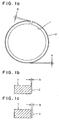
- Fig. 1 shows a piston ring 1 which constitutes one example of the present invention.
- (a) is a plan view of the piston ring as viewed in the axial direction and
- (b) is a cross-sectional view of the piston ring 1 in the radial direction of a portion opposite to butt ends, wherein A indicates a thickness of an ion plating film 2.
- (c) is a cross-sectional view of the piston ring 1 in the radial direction in the vicinity of the butt ends, wherein B indicates a thickness of the ion plating film 2.
- a steel wire or strip material capable of having arbitrary various cross-sectional shapes is formed into a coil of an approximately piston ring shape.
- an outer peripheral surface shape may be also a BF (Barrel Faced), an eccentric BF or a half BF.
- the steel wire material is coiled into a curvature which is preliminarily obtained by correcting a change of curvature generated by strain relieving heat treatment after coiling.
- This setting of curvature may change also depending on a shape of a cross-sectional area, a nominal diameter of a final ring and the alloy composition of the steel wire. Particularly, the influence of the alloy composition is large.
- the alloy composition is of high C% and contains a component such as Cr, Mo, V, Nb or the like which shows the high resistance against softening in tempering treatment, the change of curvature due to the strain relieving heat treatment after coiling is small.
- the steel wire such as spring steel which contains a small amount of such an alloy component is characterized by exhibiting a large change of curvature due to the strain relieving heat treatment after coiling.
- the steel wire material is coiled one by one using an NC control.
- the steel wire material may be formed one by one using a master cam having a given curvature in mass production in a profiling system.
- the piston ring material which is formed into a given outer peripheral curvature in the above-mentioned manner is subjected to the strain relieving heat treatment which conforms to the alloy composition so as to relieve a residual stress.
- the heat treatment conditions depend on the alloy composition of the steel wire, the steel wire is usually held at a temperature of 450 to 650 °C for 30 minutes to 1 hour.
- both side-surface grinding, outer peripheral surface grinding, and outer peripheral surface lapping are performed.
- cleaning such as pickling (acid cleaning) , alkaline degreasing or the like is performed, and the stacked piston ring blanks are set on respective positions in an ion plating equipment.
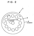
- Fig. 2 is a plan view showing the inside of the ion plating equipment 3 and shows the relationship between the position of an evaporation source 4 and the positions of stacked piston ring blanks 5.
- the stacked piston ring blanks 5 mounted on each jig such that butt ends of them are arranged in a fixed direction are arranged at 12 positions in a radial direction around the evaporation source 4 at an equal angle.
- the stacked piston ring blanks 5 revolve around the evaporation source 4 by using a planetary gear structure not shown in the drawing and, at the same time, rotate around their own axes toward the evaporation source.
- the rotation of stacked ring blanks is set such that each stacked piston ring blanks 5 performs the 215/17 rotation during a period in which it performs 1 revolution around the evaporation source 4.
- the gear ratio between the revolution and the rotation is not specifically limited to the above-mentioned value and there is no problem in choosing an arbitrary ratio. Since the rotation/revolution structure of the planetary gear system is adopted, the equipment is configured such that the rotational shafts are rotated by way of gears at the above-mentioned gear ratio by rotating the revolution shaft.
- the piston ring blanks 5 already cleaned are axially stacked on the jigs such that the butt ends are arranged in a fixed direction. These jigs are set to 12 positions respectively. Here, to make rotation of all stacked piston ring blanks set on 12 positions be in phase, they are set such that the butt ends are directed toward the center of evaporation source.
- the inside of a vessel 6 is evacuated by a vacuum pump.
- the pressure inside the vessel 6 is lowered to a value equal to or less than a given pressure, the piston ring blanks 5 are heated by a heater not shown in Fig. 2 to achieve a given temperature while being rotated around their own axes and revolved.
- the rotation/revolution speeds of respective shafts are fixed.
- film forming is started by running an arc to a known evaporation source (target).
- the film is formed by setting the rotation/revolution speeds to fixed values such that the uniform film thickness of approximately several ⁇ m is obtained.
- the rotational speed of a motor not shown in Fig. 2 is controlled such that the rotational speed in the period that the butt ends of the piston ring is directed to the center of evaporation source is set to 1/2 to 1/4 of the rotational speed in other period.
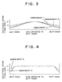
- the periodical speed control is performed such that the 17/215 rotation of the revolution shaft is set as 1cycle and during this cycle, the rotational speed in the period that the butt ends of the stacked piston ring blanks are directed toward the evaporation source becomes the minimum rotational speed, and the speed is changed with the continuous sinusoidal waveform and the speed ratio becomes 2 to 4 times.
- the butt ends of the stacked piston ring blanks 5 assume the minimum rotational speed in the period that the butt ends straightly face the center of evaporation source. Thereafter, as the butt ends are rotated to the direction opposite to the evaporattion source by 180°, the speed is continuously increased and assumes the maximum speed at the direction opposite to the evaporation source by 180°. Again, the rotational speed is continuously decelerated such that it assumes the minimum speed at the position where the butt ends straightly face the evaporation source. Accordingly, theoretically, the film thickness is continuously changed such that the film thickness at the butt ends assumes the maximum value and the film thickness at the portion opposite to the butt ends by 180° assumes the minimum value. Further, the film is formed in the same manner by adopting a method in which, the rotational speed of the stacked piston ring blanks is made slow in a fixed zone between points of time before and after the butt ends straightly face the evaporation source.
- the piston rings are cooled after film forming such that the inner temperature of the equipment assumes 100 °C and, thereafter, the pressure inside a vessel is returned to the atmospheric pressure and, thereafter, the jigs are removed.
- the piston rings are removed from respective jigs and the outer peripheral surfaces are lapped to a given surface roughness using free abrasive grains in a lapping machine. Further, side surfaces are ground when necessary.
- salt-bath nitriding or gas nitriding is performed and finish-grinding of side surfaces is performed when necessary. Finally, grinding which adjusts gap sizes between the butt ends is performed so as to obtain given piston rings 1.
- the piston ring size is in a range of 50 to 250mm ⁇
- the thickness of the film is in a range of 0.01 to 0.1mm
- carbon steel, silicon chromium steel, or martensitic stainless steel is used as the piston ring material.
- the film thickness of an outer peripheral surface of the butt ends is 40 to 55 ⁇ m.
- the coiled material is formed using an NC coiling machine with a curvature which is obtained by correcting the change of curvature attributed to the strain relieving heat treatment after coiling and, thereafter, the piston ring blanks are produced by cutting the coiled materials one by one. Thereafter, the strain relieving treatment, the both side-surface grinding, the gas nitriding treatment and an outer peripheral surface lapping are performed. Next, these piston ring blanks are subjected to cleaning such as pickling, alkaline degreasing or the like so as to clean the outer peripheral surface.
- the jigs each of which axially stack the piston ring blanks 5 which are already subjected to cleaning thereon such that the butt ends are arranged in a fixed direction are set on 12 respective positions.
- the piston ring blanks 5 are arranged such that the butt ends are directed to the center of evaporation source 4.
- the inside of the vacuum vessel is evacuated to 2.5 x 10 -4 torr using a vacuum pump and the stacked piston ring blanks 5 are heated up to a temperature of 450 °C.
- a nitrogen gas is introduced into the vacuum vessel until the degree of vacuum reaches 1 x 10 -2 torr.
- an operation mode is changed to change the rotation/revolution speeds of the stacked piston ring blanks 5. Then, at the rotational speed shown in Table 2 and using speed patterns shown in Fig. 3 and Fig. 4, an ion plating film is formed on outer peripheral surfaces of the piston ring blanks after 7 hours and 30 minutes.
- Rotational speed in azone covering 45° before and after the butt ends straight face the evaporation source is 1/2 of speed at other portion
- the film thickness of the outer peripheral surface at the butt ends and at the portion opposite to the butt ends coated under respective experimental conditions and the numbers of lapping until a contact with the outer peripheral surface is obtained with respect to each steel wire are shown in Table 4. Further, as a comparison example, a piston ring which is manufactured using a conventional ion plating film coating method is shown. In this method, the rotation speed is fixed to 6 turn/min.
- the residual stress of the CrN film is 600 to 700 MPa with respect to all specimens.
- finish grinding is performed to both side surfaces of the piston rings and, finally, grinding is performed so as to adjust a gap size between the butt ends, whereby given piston rings having a nominal diameter (d1) of 95mm, a radial wall thickness (a1) of 3.35 mm and a ring width (h1) of 2.33 mm are obtained.
- the piston rings of the present invention exhibit the small number of lapping until the contact with the whole periphery is obtained compared to the conventional piston ring and hence, it is understood that the advantageous effect of the present invention is remarkable. Further, although it is estimated that a proper value exists with respect to the difference in film thickness between the butt ends and the other portion based on the heat resistance of steels, it is apparent that the rotational speed ratio can be determined by repeating the number of experiments.
- Fig. 6 shows the fatigue strength of the outer peripheral portions of the piston rings of the comparison example and the embodiments 1 and 4. From the embodiments 1 and 4, it is evident that the fatigue strength is enhanced in both embodiments compared to the comparison example.
- the piston ring according to the present invention is effective for prevention of breakage attributed to fatigue at a position opposite to the butt ends.
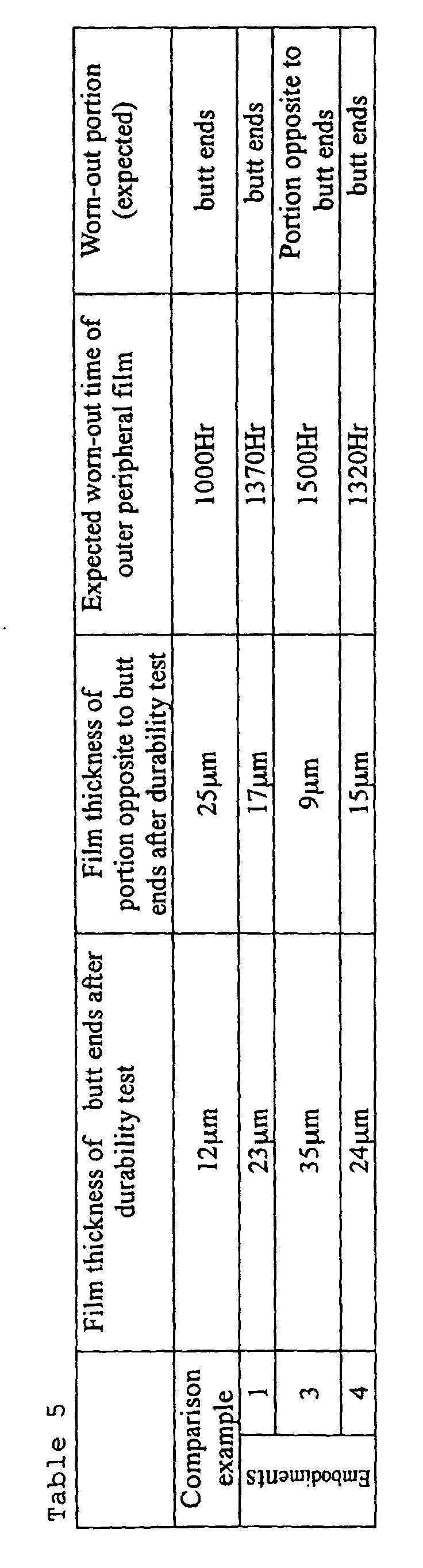
- piston ring 1 of the comparison example using the steel wire A and the piston rings 1 of the embodiments 1, 3, 4 are set to respective cylinders of a 4-cylinder diesel engine and the durability evaluation is performed at a rated output for 600 hours. Results of the evaluation are shown in Table 5.
- the ion plating film thickness of the butt ends after durability test is greater than the corresponding ion plating film thickness of other portion and hence, it is appreciated that the time until the film is worn out is prolonged compared to the conventional piston ring. That is, it is understood that the durability of the piston ring is enhanced.
- the piston ring of the present invention exhibits excellent durability and has no risk of breakage thereof.
- the hard ion plating film having high wear resistance which is coated to the outer periphery of the piston ring holds the compressive residual stress and hence, there is no risk that the film is peeled off due to fatigue even when the piston ring receives the friction force which is repeatedly loaded due to the sliding movement relative to the inner wall of the cylinder.
- the film having a large film thickness is formed on the outer peripheral surface in the vicinity of the butt ends where the sliding condition is severe so that the film is liable to be worn out. Accordingly, it is possible to eliminate conventional problems such as lowering of the sealing performance and scuffing which is generated by the rapid wear progress due to the exposure of the substrate material portion after the dissipation of the hard film. Since the hard film having a small film thickness is formed at portions other than the butt ends, even when the film is made to hold the compressive residual stress therein, the chipping of the hard film or the like hardly occurs so that the yield rate of the manufacturing process can be enhanced. Further, since the film is thin, the tensile residual stress which is generated in the substrate material portion right below the film also becomes small so that the fatigue rapture of the piston ring hardly occurs.
- the film is made thick only at portions which are liable to be worn out and hence, the film forming time can be shortened whereby the productivity using the expensive film forming equipment can be enhanced and the target consumption is also small. Accordingly, the piston ring can be manufactured at a low cost.
- the stacked piston ring blanks are mounted on a number of jigs and they are rotated around their own axes and revolved around the evaporation source which is positioned at the revolving center so as to coat ion plating films to outer peripheral surfaces of the piston rings, they are set on respective positions in the ion plating equipment such that the rotation of the butt ends of them is in phase, and the rotation/revolution speeds in the period that the butt ends straightly face the evaporation source are set lower than those in the period that the other portions straightly face the evaporation source.
- the method of the present invention exhibits the excellent mass productivity in one batch processing and, at the same time, the properties dispersion of the piston rings are also small and hence, it is possible to ensure the high stability in quality.
- the piston ring with the ion plating film coated by the above-mentioned process exhibits the small change of curvature at the outer peripheral portion of the butt ends, and hence, the lapping time can be shortened and the wear of the lapping sleeve can be reduced.
- the film thickness is inspected only at two points of the butt ends and the portion opposite to the butt ends in these embodiments, in view of the fact of the rotational speed control like sinusoidal waves and the state of contact surfaces at the time of performing lapping, it is evident that the film thickness is changed substantially continuously.
- the state of the contact surface at the time of lapping is slightly worse with respect to the piston ring which is manufactured by making the rotational speed of the butt ends slow only in the vicinity of evaporation source compared to the case of the sinusoidal waves control, the level does not cause any serious problem from a manufacturing viewpoint.
- the piston rings are formed one by one in an elliptical shape using an NC controlled coiling machine.
Landscapes
- Engineering & Computer Science (AREA)
- Chemical & Material Sciences (AREA)
- Mechanical Engineering (AREA)
- General Engineering & Computer Science (AREA)
- Chemical Kinetics & Catalysis (AREA)
- Materials Engineering (AREA)
- Metallurgy (AREA)
- Organic Chemistry (AREA)
- Combustion & Propulsion (AREA)
- Pistons, Piston Rings, And Cylinders (AREA)
- Physical Vapour Deposition (AREA)
- Injection Moulding Of Plastics Or The Like (AREA)
Abstract
Description

| Rotational speed of stacked piston ring blanks | |
| Embodiment 1 | Rotational speed is sinusoidal wave (maximum speed : minimum speed = 2 : 1), maximum speed = 6 turn/ |
| Embodiment | |
| 2 | Rotational speed is sinusoidal wave (maximum speed : minimum speed = 3 : 1), maximum speed = 6 turn/ |
| Embodiment | |
| 3 | Rotational speed is sinusoidal wave (maximum speed : minimum speed = 4 : 1), maximum speed = 6 turn/ |
| Embodiment | |
| 4 | Rotational speed in azone covering 45° before and after the butt ends straight face the evaporation source is 1/2 of speed at other portion , maximum speed = 6 turn/ |
| Embodiment | |
| 5 | Rotational speed in a zone covering 45° before and after the butt ends straight face the evaporation source is 1/3 of speed at other portion , maximum speed = 6 turn/min |
| Abrasive Material | SiC |
| Abrasive Grain Size | #4000 |
| Concentration of Abrasive Grains | 25g/litter |
| Speed | 1 stroke/second |

Claims (9)
- A piston ring having an outer peripheral surface thereof coated with a hard film, wherein a film thickness of the hard film in the vicinity of butt ends is greater than a film thickness of other outer peripheral surface.
- A piston ring according to claim 1, wherein the hard film holds a compressive residual stress.
- A piston ring according to claim 1, wherein the hard film is mainly composed of nitride.
- A piston ring according to claim 1, wherein the film thickness in the vicinity of the butt ends is 1.5 to 4 times as thick as the film thickness at a portion opposite to the butt ends.
- A piston ring according to claim 1, wherein the film thickness of an outer peripheral surface of the butt ends is 40 to 55µm.
- An ion plating film forming method for piston rings in which stacked piston ring blanks are rotated around their own axes and revolved around an evaporation source, wherein a rotational speed at a point of time that butt ends straightly face the evaporation source or during a period ranging from before to after the butt ends straightly face the evaporation source is set slower than a rotational speed when other portions straightly face the evaporation source.
- An ion plating film forming method according to claim 6, wherein a maximum value of the rotational speed is within twice as fast as a minimum speed.
- An ion plating film forming method according to claim 7, wherein the rotation speed is changed in a form of sinusoidal waves.
- A method for manufacturing the piston ring described in any one of claims 1 to 3, wherein stacked piston ring blanks are mounted on a number of jigs, the stacked piston ring blanks are rotated around their own axes and revolved around an evaporation source which is positioned at a revolving center, at the time of coating an ion plating film to outer peripheral surfaces of the stacked piston ring blanks, the stacked piston ring blanks are set on respective positions in an ion plating equipment such that rotation of the butt ends is in phase, and the rotation/revolution speeds when the butt ends straightly face the evaporation source are made slower than the rotation/revolution speeds when other portions straightly face the evaporation source.
Applications Claiming Priority (3)
| Application Number | Priority Date | Filing Date | Title |
|---|---|---|---|
| JP2000395674 | 2000-12-26 | ||
| JP2000395674A JP4680380B2 (en) | 2000-12-26 | 2000-12-26 | Piston ring and manufacturing method thereof |
| PCT/JP2001/011278 WO2002052179A1 (en) | 2000-12-26 | 2001-12-21 | Piston ring and method of producing the same |
Publications (3)
| Publication Number | Publication Date |
|---|---|
| EP1359351A1 true EP1359351A1 (en) | 2003-11-05 |
| EP1359351A4 EP1359351A4 (en) | 2005-04-13 |
| EP1359351B1 EP1359351B1 (en) | 2009-03-04 |
Family
ID=18861098
Family Applications (1)
| Application Number | Title | Priority Date | Filing Date |
|---|---|---|---|
| EP01994989A Expired - Lifetime EP1359351B1 (en) | 2000-12-26 | 2001-12-21 | Piston ring and method of producing the same |
Country Status (8)
| Country | Link |
|---|---|
| US (1) | US7052019B2 (en) |
| EP (1) | EP1359351B1 (en) |
| JP (1) | JP4680380B2 (en) |
| KR (1) | KR20030061469A (en) |
| CN (1) | CN100549471C (en) |
| BR (1) | BR0116580B1 (en) |
| DE (1) | DE60137872D1 (en) |
| WO (1) | WO2002052179A1 (en) |
Cited By (5)
| Publication number | Priority date | Publication date | Assignee | Title |
|---|---|---|---|---|
| WO2008068613A1 (en) * | 2006-12-05 | 2008-06-12 | Mahle International Gmbh | Piston ring for internal combustion engines |
| WO2012107012A1 (en) * | 2011-02-09 | 2012-08-16 | Federal-Mogul Burscheid Gmbh | Piston ring |
| WO2015082538A1 (en) * | 2013-12-03 | 2015-06-11 | Mahle Metal Leve S/A | Piston ring |
| JP2016520779A (en) * | 2013-06-04 | 2016-07-14 | フェデラル−モーグル ブルシェイド ゲーエムベーハーFederal−Mogul Burscheid Gmbh | Method for manufacturing a piston ring |
| WO2017167817A1 (en) * | 2016-03-31 | 2017-10-05 | Mahle Metal Leve S/A | Piston ring for an internal-combustion engine, and method for obtaining a piston ring and an internal-combustion engine |
Families Citing this family (30)
| Publication number | Priority date | Publication date | Assignee | Title |
|---|---|---|---|---|
| JP4548975B2 (en) * | 2001-06-14 | 2010-09-22 | 帝国ピストンリング株式会社 | Method for measuring residual stress of film |
| US8002830B2 (en) * | 2004-02-06 | 2011-08-23 | Georgia Tech Research Corporation | Surface directed cellular attachment |
| USD557906S1 (en) | 2006-01-31 | 2007-12-25 | Richard James Thomson | Hanger |
| JP5060083B2 (en) * | 2006-08-24 | 2012-10-31 | トクセン工業株式会社 | Piston ring manufacturing method |
| USD583573S1 (en) | 2007-09-20 | 2008-12-30 | Richard James Thomson | Hanger |
| CN101978085B (en) * | 2008-03-27 | 2013-07-24 | 日立金属株式会社 | Piston ring material for internal combustion engine |
| JP5199799B2 (en) * | 2008-03-31 | 2013-05-15 | シチズンファインテックミヨタ株式会社 | Vacuum deposition method and vacuum deposition apparatus |
| DE102009010727B3 (en) * | 2009-02-26 | 2011-01-13 | Federal-Mogul Burscheid Gmbh | Cast steel material composition for producing piston rings and cylinder liners |
| DE102009010726B3 (en) * | 2009-02-26 | 2010-12-09 | Federal-Mogul Burscheid Gmbh | Piston rings and cylinder liners |
| DE102009010728C5 (en) * | 2009-02-26 | 2019-08-14 | Federal-Mogul Burscheid Gmbh | Piston rings and cylinder liners |
| DE102009015009B3 (en) * | 2009-03-26 | 2010-12-09 | Federal-Mogul Burscheid Gmbh | piston ring |
| BRPI0903320A2 (en) * | 2009-09-24 | 2011-05-24 | Mahle Metal Leve Sa | piston ring and process of manufacturing a piston ring |
| DE102009052587A1 (en) * | 2009-11-10 | 2011-05-12 | Federal-Mogul Burscheid Gmbh | piston ring |
| DE102010046551B4 (en) * | 2010-09-27 | 2014-09-04 | Federal-Mogul Burscheid Gmbh | Method for producing a piston ring |
| DE102010048079B4 (en) * | 2010-10-09 | 2013-03-28 | Federal-Mogul Burscheid Gmbh | Method for producing a piston ring |
| BR102013012133A2 (en) | 2013-05-15 | 2015-05-26 | Mahle Metal Leve Sa | Piston ring |
| WO2014196614A1 (en) * | 2013-06-07 | 2014-12-11 | 株式会社リケン | Piston ring, raw material therefor, and production method for both |
| JP5859048B2 (en) * | 2014-03-20 | 2016-02-10 | サンコール株式会社 | Piston ring and metal rectangular wire for piston ring |
| BR102014025243B1 (en) * | 2014-10-09 | 2022-09-27 | Mahle Metal Leve S/A | PISTON RING FOR INTERNAL COMBUSTION ENGINES, PROCESS FOR OBTAINING PISTON RING AND INTERNAL COMBUSTION ENGINE |
| JP6498986B2 (en) * | 2015-03-26 | 2019-04-10 | 株式会社リケン | piston ring |
| JP6784608B2 (en) * | 2017-02-09 | 2020-11-11 | 株式会社神戸製鋼所 | Film forming equipment and manufacturing method of film |
| JP6763802B2 (en) * | 2017-02-21 | 2020-09-30 | 株式会社神戸製鋼所 | Work rotation device and film forming device equipped with it |
| BR102017007599B1 (en) * | 2017-04-12 | 2022-07-26 | Mahle Metal Leve S.A. | PISTON RING FOR INTERNAL COMBUSTION ENGINES |
| US11156291B2 (en) * | 2017-06-02 | 2021-10-26 | Mahle International Gmbh | Piston ring and method of manufacture |
| US11162586B2 (en) | 2017-06-02 | 2021-11-02 | Mahle International Gmbh | Piston ring and method of manufacture |
| DE102017210559A1 (en) * | 2017-06-22 | 2018-12-27 | Mahle International Gmbh | Piston ring for a piston of an internal combustion engine |
| WO2019208551A1 (en) * | 2018-04-27 | 2019-10-31 | 株式会社神戸製鋼所 | Film deposition device and film deposition method |
| CN108757931A (en) * | 2018-06-22 | 2018-11-06 | 南通迅达橡塑制造有限公司 | A kind of vacuum adsorption type rubber seal |
| JP7085692B2 (en) * | 2020-01-27 | 2022-06-16 | 株式会社リケン | Piston ring and its manufacturing method |
| CN117305800B (en) * | 2023-11-29 | 2024-02-13 | 长沙正圆动力科技有限责任公司 | Piston ring coating machine with multidimensional rotating frame |
Family Cites Families (21)
| Publication number | Priority date | Publication date | Assignee | Title |
|---|---|---|---|---|
| US1783047A (en) * | 1927-06-01 | 1930-11-25 | Lewis C Marshall | Method of making steel piston rings |
| DE1000651B (en) * | 1956-02-23 | 1957-01-10 | Goetzewerke | Piston ring |
| US2905512A (en) * | 1958-04-24 | 1959-09-22 | Ramsey Corp | Coated piston ring |
| DE1222748B (en) * | 1962-08-04 | 1966-08-11 | Goetzewerke | Piston ring |
| US4299401A (en) * | 1979-09-12 | 1981-11-10 | Ramsey Corporation | Piston ring and method of making same |
| JPS5910366Y2 (en) * | 1980-05-21 | 1984-04-02 | 株式会社リケン | piston ring |
| RU2021553C1 (en) * | 1991-07-08 | 1994-10-15 | Инженерный центр "Конверсия" | Piston ring |
| JPH0727228A (en) * | 1993-07-07 | 1995-01-27 | Teikoku Piston Ring Co Ltd | Sliding member and crn film coating method |
| JP3266375B2 (en) | 1993-07-08 | 2002-03-18 | 帝国ピストンリング株式会社 | Coiling equipment |
| JP2771947B2 (en) | 1994-04-21 | 1998-07-02 | 株式会社リケン | Sliding member |
| US5601293A (en) * | 1994-12-22 | 1997-02-11 | Teikoku Piston Ring Co., Ltd. | Sliding member with hard ternery film |
| JP3464320B2 (en) * | 1995-08-02 | 2003-11-10 | 株式会社荏原製作所 | Processing method and processing apparatus using high-speed atomic beam |
| RU2110693C1 (en) * | 1996-04-01 | 1998-05-10 | Челябинский государственный технический университет | Piston ring for internal combustion engine or piston compressor |
| JP3420900B2 (en) * | 1996-10-21 | 2003-06-30 | 大日本スクリーン製造株式会社 | Coating liquid application method |
| JPH10140351A (en) * | 1996-11-05 | 1998-05-26 | Kobe Steel Ltd | Inline type vacuum film forming device |
| JPH10252890A (en) | 1997-03-13 | 1998-09-22 | Kanai Hiroaki | Oil ring |
| US5912049A (en) * | 1997-08-12 | 1999-06-15 | Micron Technology, Inc. | Process liquid dispense method and apparatus |
| DE69841227D1 (en) * | 1997-11-18 | 2009-11-19 | Panasonic Corp | Multilayer product, capacitor and method of making the multi-layered product |
| JPH11152558A (en) * | 1997-11-18 | 1999-06-08 | Suzuki Motor Corp | Wear-resistant sliding member |
| JP3792413B2 (en) | 1998-10-19 | 2006-07-05 | 日本ピストンリング株式会社 | piston ring |
| JP4282821B2 (en) | 1999-03-23 | 2009-06-24 | 帝国ピストンリング株式会社 | Sliding member |
-
2000
- 2000-12-26 JP JP2000395674A patent/JP4680380B2/en not_active Expired - Fee Related
-
2001
- 2001-12-21 KR KR10-2003-7008577A patent/KR20030061469A/en not_active Ceased
- 2001-12-21 BR BRPI0116580-1A patent/BR0116580B1/en not_active IP Right Cessation
- 2001-12-21 DE DE60137872T patent/DE60137872D1/en not_active Expired - Lifetime
- 2001-12-21 EP EP01994989A patent/EP1359351B1/en not_active Expired - Lifetime
- 2001-12-21 US US10/451,732 patent/US7052019B2/en not_active Expired - Fee Related
- 2001-12-21 CN CNB018228739A patent/CN100549471C/en not_active Expired - Fee Related
- 2001-12-21 WO PCT/JP2001/011278 patent/WO2002052179A1/en not_active Ceased
Cited By (13)
| Publication number | Priority date | Publication date | Assignee | Title |
|---|---|---|---|---|
| US8157268B2 (en) | 2006-12-05 | 2012-04-17 | Mahle International Gmbh | Piston for internal combustion engines |
| WO2008068613A1 (en) * | 2006-12-05 | 2008-06-12 | Mahle International Gmbh | Piston ring for internal combustion engines |
| RU2573549C2 (en) * | 2011-02-09 | 2016-01-20 | Федерал-Моугал Буршайд Гмбх | Piston ring |
| WO2012107012A1 (en) * | 2011-02-09 | 2012-08-16 | Federal-Mogul Burscheid Gmbh | Piston ring |
| US8979094B2 (en) | 2011-02-09 | 2015-03-17 | Federal-Mogul Burscheid Gmbh | Piston ring |
| JP2016520779A (en) * | 2013-06-04 | 2016-07-14 | フェデラル−モーグル ブルシェイド ゲーエムベーハーFederal−Mogul Burscheid Gmbh | Method for manufacturing a piston ring |
| EP3004414B1 (en) | 2013-06-04 | 2018-06-13 | Federal-Mogul Burscheid GmbH | Method for producing a piston ring |
| RU2661352C2 (en) * | 2013-06-04 | 2018-07-16 | Федерал-Моугал Буршайд Гмбх | Method of producing a piston ring |
| US10370755B2 (en) | 2013-06-04 | 2019-08-06 | Wilmington Trust, National Association, As Collateral Trustee | Method for producing piston a ring |
| WO2015082538A1 (en) * | 2013-12-03 | 2015-06-11 | Mahle Metal Leve S/A | Piston ring |
| US9759324B2 (en) | 2013-12-03 | 2017-09-12 | Mahle Metal Leve S/A | Piston ring |
| WO2017167817A1 (en) * | 2016-03-31 | 2017-10-05 | Mahle Metal Leve S/A | Piston ring for an internal-combustion engine, and method for obtaining a piston ring and an internal-combustion engine |
| US10724637B2 (en) | 2016-03-31 | 2020-07-28 | Mahle Metal Level S/A | Piston ring for an internal-combustion engine, a method for coating a piston ring, and an internal-combustion engine |
Also Published As
| Publication number | Publication date |
|---|---|
| BR0116580B1 (en) | 2010-12-28 |
| JP4680380B2 (en) | 2011-05-11 |
| EP1359351A4 (en) | 2005-04-13 |
| BR0116580A (en) | 2004-01-06 |
| EP1359351B1 (en) | 2009-03-04 |
| CN1492978A (en) | 2004-04-28 |
| JP2002195409A (en) | 2002-07-10 |
| CN100549471C (en) | 2009-10-14 |
| WO2002052179A1 (en) | 2002-07-04 |
| US7052019B2 (en) | 2006-05-30 |
| US20040056425A1 (en) | 2004-03-25 |
| DE60137872D1 (en) | 2009-04-16 |
| KR20030061469A (en) | 2003-07-18 |
Similar Documents
| Publication | Publication Date | Title |
|---|---|---|
| EP1359351B1 (en) | Piston ring and method of producing the same | |
| JP6062357B2 (en) | piston ring | |
| US7572344B2 (en) | Method for the production of wear-resistant sides for a keystone ring for internal combustion engine | |
| JP7508747B2 (en) | piston ring | |
| US20080256794A1 (en) | Method For the Production of a Piston Ring For Internal Combustion Engine and a Piston Ring of this Type | |
| US11162587B2 (en) | Piston ring and method for manufacturing a piston ring | |
| EP0707092A1 (en) | Slide member and method of its production | |
| GB2303640A (en) | Sliding member with film containing chromium and chromium nitride | |
| EP3802905B1 (en) | Piston ring and method for manufacturing a piston ring | |
| JP6757769B2 (en) | piston ring | |
| JPS6113064A (en) | Piston ring for internal-combustion engine | |
| EP1717487A1 (en) | Rolling sliding part | |
| JP2002115045A (en) | Film deposition method, and vane for movable vane compressor | |
| JP4202000B2 (en) | Mandrel for ring rolling | |
| JP2649835B2 (en) | piston ring | |
| JPH02134468A (en) | Piston ring | |
| JPH0378507A (en) | Outer ring of cam follower device for engine valve mechanism and its processing method | |
| RU2226146C2 (en) | Method of finishing cylinder liner working surface | |
| JPH10306386A (en) | Hard coating material, sliding member coated with this and production thereof | |
| JP4877502B2 (en) | Nitrogen-containing Cr coating and mechanical member having this coating | |
| JPS6357964A (en) | Piston ring | |
| JPH02154865A (en) | Piston ring | |
| JP2002003976A (en) | Sliding member | |
| JP2004124888A (en) | Eccentric BF-shaped piston ring and its manufacturing method | |
| JPH02134467A (en) | Piston ring |
Legal Events
| Date | Code | Title | Description |
|---|---|---|---|
| PUAI | Public reference made under article 153(3) epc to a published international application that has entered the european phase |
Free format text: ORIGINAL CODE: 0009012 |
|
| 17P | Request for examination filed |
Effective date: 20030725 |
|
| AK | Designated contracting states |
Kind code of ref document: A1 Designated state(s): AT BE CH CY DE DK ES FI FR GB GR IE IT LI LU MC NL PT SE TR |
|
| RBV | Designated contracting states (corrected) |
Designated state(s): BE DE ES FR GB IT |
|
| A4 | Supplementary search report drawn up and despatched |
Effective date: 20050301 |
|
| RIC1 | Information provided on ipc code assigned before grant |
Ipc: 7C 23C 14/32 B Ipc: 7F 16J 9/26 A Ipc: 7F 16J 9/14 B Ipc: 7C 23C 14/50 B |
|
| 17Q | First examination report despatched |
Effective date: 20060911 |
|
| GRAP | Despatch of communication of intention to grant a patent |
Free format text: ORIGINAL CODE: EPIDOSNIGR1 |
|
| GRAS | Grant fee paid |
Free format text: ORIGINAL CODE: EPIDOSNIGR3 |
|
| GRAA | (expected) grant |
Free format text: ORIGINAL CODE: 0009210 |
|
| AK | Designated contracting states |
Kind code of ref document: B1 Designated state(s): BE DE ES FR GB IT |
|
| REG | Reference to a national code |
Ref country code: GB Ref legal event code: FG4D |
|
| REF | Corresponds to: |
Ref document number: 60137872 Country of ref document: DE Date of ref document: 20090416 Kind code of ref document: P |
|
| PG25 | Lapsed in a contracting state [announced via postgrant information from national office to epo] |
Ref country code: BE Free format text: LAPSE BECAUSE OF FAILURE TO SUBMIT A TRANSLATION OF THE DESCRIPTION OR TO PAY THE FEE WITHIN THE PRESCRIBED TIME-LIMIT Effective date: 20090304 |
|
| PG25 | Lapsed in a contracting state [announced via postgrant information from national office to epo] |
Ref country code: ES Free format text: LAPSE BECAUSE OF FAILURE TO SUBMIT A TRANSLATION OF THE DESCRIPTION OR TO PAY THE FEE WITHIN THE PRESCRIBED TIME-LIMIT Effective date: 20090615 |
|
| PLBE | No opposition filed within time limit |
Free format text: ORIGINAL CODE: 0009261 |
|
| STAA | Information on the status of an ep patent application or granted ep patent |
Free format text: STATUS: NO OPPOSITION FILED WITHIN TIME LIMIT |
|
| 26N | No opposition filed |
Effective date: 20091207 |
|
| GBPC | Gb: european patent ceased through non-payment of renewal fee |
Effective date: 20091221 |
|
| REG | Reference to a national code |
Ref country code: FR Ref legal event code: ST Effective date: 20100831 |
|
| PG25 | Lapsed in a contracting state [announced via postgrant information from national office to epo] |
Ref country code: FR Free format text: LAPSE BECAUSE OF NON-PAYMENT OF DUE FEES Effective date: 20091231 |
|
| PG25 | Lapsed in a contracting state [announced via postgrant information from national office to epo] |
Ref country code: GB Free format text: LAPSE BECAUSE OF NON-PAYMENT OF DUE FEES Effective date: 20091221 |
|
| PG25 | Lapsed in a contracting state [announced via postgrant information from national office to epo] |
Ref country code: IT Free format text: LAPSE BECAUSE OF FAILURE TO SUBMIT A TRANSLATION OF THE DESCRIPTION OR TO PAY THE FEE WITHIN THE PRESCRIBED TIME-LIMIT Effective date: 20090304 |
|
| PGFP | Annual fee paid to national office [announced via postgrant information from national office to epo] |
Ref country code: DE Payment date: 20151215 Year of fee payment: 15 |
|
| REG | Reference to a national code |
Ref country code: DE Ref legal event code: R082 Ref document number: 60137872 Country of ref document: DE Representative=s name: WINTER, BRANDL, FUERNISS, HUEBNER, ROESS, KAIS, DE |
|
| REG | Reference to a national code |
Ref country code: DE Ref legal event code: R119 Ref document number: 60137872 Country of ref document: DE |
|
| PG25 | Lapsed in a contracting state [announced via postgrant information from national office to epo] |
Ref country code: DE Free format text: LAPSE BECAUSE OF NON-PAYMENT OF DUE FEES Effective date: 20170701 |