EP1359377A1 - Katalytischer Brenner - Google Patents
Katalytischer Brenner Download PDFInfo
- Publication number
- EP1359377A1 EP1359377A1 EP03100949A EP03100949A EP1359377A1 EP 1359377 A1 EP1359377 A1 EP 1359377A1 EP 03100949 A EP03100949 A EP 03100949A EP 03100949 A EP03100949 A EP 03100949A EP 1359377 A1 EP1359377 A1 EP 1359377A1
- Authority
- EP
- European Patent Office
- Prior art keywords
- swirl generator
- burner
- catalyst
- channels
- catalysts
- Prior art date
- Legal status (The legal status is an assumption and is not a legal conclusion. Google has not performed a legal analysis and makes no representation as to the accuracy of the status listed.)
- Granted
Links
Images




Classifications
-
- F—MECHANICAL ENGINEERING; LIGHTING; HEATING; WEAPONS; BLASTING
- F23—COMBUSTION APPARATUS; COMBUSTION PROCESSES
- F23R—GENERATING COMBUSTION PRODUCTS OF HIGH PRESSURE OR HIGH VELOCITY, e.g. GAS-TURBINE COMBUSTION CHAMBERS
- F23R3/00—Continuous combustion chambers using liquid or gaseous fuel
- F23R3/40—Continuous combustion chambers using liquid or gaseous fuel characterised by the use of catalytic means
-
- F—MECHANICAL ENGINEERING; LIGHTING; HEATING; WEAPONS; BLASTING
- F23—COMBUSTION APPARATUS; COMBUSTION PROCESSES
- F23D—BURNERS
- F23D14/00—Burners for combustion of a gas, e.g. of a gas stored under pressure as a liquid
- F23D14/46—Details
- F23D14/72—Safety devices, e.g. operative in case of failure of gas supply
- F23D14/78—Cooling burner parts
-
- F—MECHANICAL ENGINEERING; LIGHTING; HEATING; WEAPONS; BLASTING
- F23—COMBUSTION APPARATUS; COMBUSTION PROCESSES
- F23R—GENERATING COMBUSTION PRODUCTS OF HIGH PRESSURE OR HIGH VELOCITY, e.g. GAS-TURBINE COMBUSTION CHAMBERS
- F23R3/00—Continuous combustion chambers using liquid or gaseous fuel
- F23R3/02—Continuous combustion chambers using liquid or gaseous fuel characterised by the air-flow or gas-flow configuration
- F23R3/04—Air inlet arrangements
- F23R3/10—Air inlet arrangements for primary air
- F23R3/12—Air inlet arrangements for primary air inducing a vortex
-
- F—MECHANICAL ENGINEERING; LIGHTING; HEATING; WEAPONS; BLASTING
- F23—COMBUSTION APPARATUS; COMBUSTION PROCESSES
- F23R—GENERATING COMBUSTION PRODUCTS OF HIGH PRESSURE OR HIGH VELOCITY, e.g. GAS-TURBINE COMBUSTION CHAMBERS
- F23R3/00—Continuous combustion chambers using liquid or gaseous fuel
- F23R3/28—Continuous combustion chambers using liquid or gaseous fuel characterised by the fuel supply
- F23R3/34—Feeding into different combustion zones
Definitions
- the invention relates to a catalytic burner on or for one Combustion chamber, in particular a power plant, with the features of Preamble of claim 1.
- a catalytic burner of this type is known a catalyst arranged in a ring and flowed through in burner operation and has a swirl generator through which the burner operates. It is the swirl generator is designed as an axial swirl generator in the axial direction is flowed through and the flow is subjected to a swirl. The axial swirl generator is concentric within the catalyst arranged so that the catalyst and swirl generator are flowed through in parallel.
- the present invention addresses the problem for one an improved catalytic burner of the type mentioned Specify embodiment, in particular the stability of the Combustion in the combustion chamber is increased.
- the invention is based on the general idea for the application of Burner flow with a swirl using a radial swirl generator i.e. a swirl generator, which is flowed through radially and thereby an axial emerging swirl flow generated.
- a radial swirl generator i.e. a swirl generator
- the flow resistance is smaller than one axial swirl generator. Accordingly, in the case of the invention Burner a smaller pressure drop, which is of particular advantage here, as well Flow through the catalyst or catalysts always with a pressure drop accompanied.
- the radial swirl generator have several rectilinear swirl generator channels, each opposite the Radial direction are inclined in the circumferential direction and a radially outer Connect the inflow space with a radially inner outflow space.
- This Construction has a relatively low flow resistance.
- the rectilinear swirl generator channels have one along their longitudinal direction constant cross-section, which makes it particularly easy constructed and therefore inexpensive catalysts in the swirl generator channels use.
- conventional monolith catalysts can be used rectilinear and parallel catalyst channels or cells can be used. This makes it possible to use standard components, which is special is inexpensive.
- catalysts can also be used that are made of zigzag folded or undulating sheets multilayer folding, layering or wrapping can be produced.
- a burner 1 according to the invention is connected to a combustion chamber 2 connected, in the combustion chamber 3 hot in the burner operation Combustion gases are generated at a preferred rate Application form of a gas turbine are fed to a power plant.
- the Burner 1 contains a catalyst arrangement 4 consisting of several Catalysts 5, which are flowed through in burner operation. Accordingly it is a catalytic burner 1.
- This burner 1 contains also a swirl generator 6, which is designed as a radial swirl generator, i.e.
- the swirl generator 6 is flowed through radially, here radially from the outside inside, giving the flow a twist.
- the radial swirl generator 6 is thereby between a radially outer inflow space 7 and a radial one outflow chamber 8 arranged inside.
- the swirl generator 6 and the Catalyst arrangement 4 are concentric with a longitudinal axis 9 of the Burner 1 arranged.
- the outflow chamber 8 leads in the axial direction, that is parallel to the longitudinal axis 9 to the combustion chamber 2 and thus connects the Downstream side of the swirl generator 6 with the combustion chamber 3.
- a transition 10 between the outflow chamber 8 and the combustion chamber 3 has here a cross-sectional enlargement 11, which in particular has a jump-like design can be.
- This cross-sectional widening 11 allows the burner 1 generated swirl flow in the combustion chamber 3 quasi burst, whereby on the one hand In the area of the cross-sectional expansion 11, a first vortex system 12 is generated and, on the other hand, a central second swirl system 13 in the combustion chamber 3 is generated.
- the second swirl system 13 is in the combustion chamber 2 generates a central recirculation zone 14 which has a flame front 15 in the Combustion chamber 2 in the so-called "plenum", ie in the vicinity of burner 1 anchored and stabilized.
- the radial swirl generator 6 has several Swirl generator channels 16, each in the same way opposite one of the central longitudinal axis 9 outgoing radial direction in the circumferential direction are inclined. This orientation of the swirl generator channels 16 results in the flow of the desired swirl. They are useful Swirl generator channels 16 tangential to an outlet cross section 17 aligned through which the gas flow from the outflow chamber 8 in the Combustion chamber 3 enters.
- the swirl generator channels 16 are expediently rectilinear and with one in their Longitudinal direction constant cross section formed. This makes it possible Particularly simple catalysts 5 in the swirl generator channels 16 use.
- the individual catalysts 5 consist of ceramic monoliths, which are coated in a suitable manner catalytically. It is also possible to use a stack or a catalyst 5 To build up winding of corrugated or zigzag folded sheet metal webs, the are also catalytically activated by a suitable coating.
- the Catalysts 5 each contain a large number of unspecified ones Catalyst channels, each parallel to and parallel to the Swirl generator channels 16 run.
- the catalysts 5 are arranged in the radial swirl generator 6, they take place Positioning on a radius that is larger than the radius of the Outlet cross section 17. Accordingly, the flow for Catalysts 5 have a smaller pressure drop than in a comparable arrangement with a pure axial flow.
- the flow rate in the Catalyst channels and the pressure loss of the catalysts 5 can on the one hand over the length of the catalysts 5 and their cell density and by the axial extension of the catalysts 5 and the swirl generator channels 16 and thus the swirl generator 6 can be set.
- the interpretation is expedient of the burner 1 so that the burner operation at least in the outflow chamber 8 Flow velocity is greater than a turbulent Flame speed at which the flame front 15 faces the burner 1 want to spread.
- This measure can spread the Flame front 15 in the outflow chamber 8 can be avoided.
- the burner 1 is designed so that a Dwell time of the flow in the outflow chamber 8 is less than one Time delay until self-ignition in the outflow chamber 8 inflowing, partially reacted hot fuel-oxidizer mixture.
- this measure can be the hot gas generation provided for the combustion chamber 3 be kept away from the outflow chamber 8. Wear the measures mentioned in each case that overheating of the catalysts 5 or Swirl generator 6 can be avoided.
- the embodiment of the Burner 1 a primary injection device 18, the multiple injectors 19th has that to a common ring line 20 for fuel supply are connected.
- the ring line is via a fuel feed line 25 fueled.
- the primary injection device conducts 18 upstream of the catalyst arrangement 4 in burner operation and thus upstream of the swirl generator 6 into the inflow space 7, in which the injectors 19 are arranged.
- the primary injector 18 has one for each swirl generator channel 16 has a separate injector 19, the fuel directly into the respective Swirl generator channel 16 injected or injected.
- Adequate Mixing of the introduced fuel with the supplied gas flow can be achieved in each swirl generator channel 16 upstream of the catalysts 5 an inlet section 21 can be formed, which serves as a mixing space.
- a secondary injection device 22 is also provided, the for the introduction of fuel downstream of the catalyst assembly 4 in the Outflow chamber 8 is used.
- This secondary injection device 22 has one here central, ie coaxial to the longitudinal axis 9 aligned injector 23, the is expediently designed or aligned so that it is in the fuel substantially parallel to the longitudinal axis 9 in the direction of the combustion chamber 2 in the Abströmraum 8 injected or injected.
- the secondary injection device can likewise 22 have a plurality of injectors 23.
- the injector (s) 23 of the secondary injector 22 also can be arranged eccentrically to the longitudinal axis 9. In particular, too lateral injection of the secondary fuel into the outflow space 8 be appropriate.
- the secondary injection device 22 can be used to start the burner 1 or sufficient combustion for transient operating conditions Combustion chamber 2 can be realized. Such a "pilot operation" is, for example required if the catalysts 5 are not yet sufficiently high Have reached operating temperature.
- the discharge of secondary fuel can in addition to the transient operating states when the burner 1 is started up at partial load conditions may be beneficial to the reliability of the Increase burner operation.
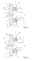
- FIGS. 5 to 8 show embodiments in which the injectors 19 quasi axially the fuel into the inflow space 7 inject or inject. 5 and 7 show an almost only axial injection, while in Fig. 6 the fuel for Is injected inclined towards the longitudinal axis, so that the introduced fuel also receives a radial component. The injection is still carried out outside of the swirl generator channels 16, but in the Swirl generator channels 16 entering gas flow takes the fuel and in deflects the inlet sections 21.
- each Swirl generator channel 16 is arranged at least one catalyst 5
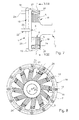
- the Fig. 9 and 10 an embodiment in which in the circumferential direction only in every second Swirl generator channel 16 a catalyst 5 is arranged. Because of this design may also overheat the catalysts 5 or the swirl generator 6 be avoided.
- An embodiment is particularly expedient here has two primary injectors 18 and 18 ', the first primary injector 18 those swirl generator channels 16 with fuel supplied, in each of which one of the catalysts 5 is arranged. in the In contrast to this, the second primary injection device 18 'supplies the others Swirl generator channels 16, in which no catalyst 5 is arranged.
- Swirl generator channel 16 is equipped with a catalyst 5, can be used in a another embodiment also a different distribution of the catalysts 5 the swirl generator channels 16 are realized.
- the two catalysts 5a expediently differ and 5b for their catalytic activity. For example, the upstream arranged catalyst 5a have a higher activity to the Start the combustion reaction while the downstream catalyst 5b has a lower activity to overheat the catalyst 5b avoid.
- measures are exemplary shown, with the help of a wall 27 of the outflow chamber 8 against Overheating can be protected.
- This is conveniently done in the form of a active cooling and / or in the form of passive thermal protection.
- Film cooling 28 realized along the wall 27.
- FIG. 13 is the thermally loaded wall 27 with a heat protection layer 29 provided which the heat generated in the outflow chamber 8 from the wall 27 holds.
- the wall 27 between the swirl generator 6 and the combustion chamber 2 with the aid of cooling 30 actively cooled. For example, the cooling takes place through the application the wall 27 with cooling gas.
Landscapes
- Engineering & Computer Science (AREA)
- Chemical & Material Sciences (AREA)
- Combustion & Propulsion (AREA)
- Mechanical Engineering (AREA)
- General Engineering & Computer Science (AREA)
- Chemical Kinetics & Catalysis (AREA)
Abstract
Description
- Fig. 1
- einen Längsschnitt durch eine stark vereinfachte Prinzipdarstellung eines erfindungsgemäßen Brenners,
- Fig. 2
- einen Querschnitt durch den Brenner gemäß Fig. 1 e ntsprechend den Schnittlinien II,
- Fig.3
- ein weiter vereinfachter Längsschnitt durch den Brenner bei einer anderen Ausführungsform,
- Fig. 4
- einen Querschnitt durch den Brenner gemäß Fig. 3 entsprechend den Schnittlinien IV,
- Fig. 5 und 6
- jeweils einen Längsschnitt wie in Fig. 3, jedoch bei anderen Ausführungsformen,
- Fig. 7
- einen Längsschnitt wie in Fig. 5, jedoch bei einer Weiterbildung,
- Fig. 8
- einen Querschnitt durch den Brenner gemäß Fig. 5 entsprechend den Schnittlinien VIII,
- Fig. 9
- einen Längsschnitt wie in Fig. 7, jedoch bei einer anderen Ausführungsform,
- Fig.10
- einen Querschnitt durch den Brenner gemäß Fig. 9 entsprechend den Schnittlinien X,
- Fig.11 bis 14
- vereinfachte Längsschnitte durch den Brenner bei unterschiedlichen Ausführungsformen.
- 1
- Brenner
- 2
- Brennkammer
- 3
- Brennraum
- 4
- Katalysatoranordnung
- 5
- Katalysator
- 6
- Drallerzeuger
- 7
- Zuströmraum
- 8
- Abströmraum
- 9
- Längsachse von 1
- 10
- Übergang zwischen 8 und 2
- 11
- Querschnittserweiterung
- 12
- erstes Wirbelsystem
- 13
- zweites Wirbelsystem
- 14
- Rezirkulationszone
- 15
- Flammenfront
- 16
- Drallerzeugerkanal
- 17
- Austrittsquerschnitt von 8
- 18
- Primär-Einspritzeinrichtung
- 19
- Injektor
- 20
- Ringleitung
- 21
- Einlassabschnitt von 16
- 22
- Sekundär-Einspritzeinrichtung
- 23
- Injektor
- 24
- Mischeinrichtung
- 25
- Brennstoffzuführungsleitung
- 26
- Mischzone
- 27
- Wandung von 8
- 28
- Filmkühlung
- 29
- Wärmeschutzschicht
- 30
- Kühlung
Claims (15)
- Katalytischer Brenner an einer oder für eine Brennkammer (2), insbesondere einer Kraftwerksanlage, mit wenigstens einem im Brennerbetrieb durchströmten Katalysator (5) und mit einem im Brennerbetrieb durchströmten Drallerzeuger (6),
dadurch gekennzeichnet, dass der Drallerzeuger als radialer Drallerzeuger (6) ausgebildet ist, der zwischen einem radial außen liegenden Zuströmraum (7) und einem radial innen liegenden, axial zur Brennkammer (2) führenden Abströmraum (8) angeordnet ist. - Brenner nach Anspruch 1,
dadurch gekennzeichnet, dass der radiale Drallerzeuger (6) mehrere geradlinige Drallerzeugerkanäle (16) aufweist, die jeweils gegenüber der Radialrichtung in Umfangsrichtung geneigt sind und den Zuströmraum (7) mit dem Abströmraum (8) verbinden. - Brenner nach Anspruch 2,
dadurch gekennzeichnet, dass zumindest in einigen der Drallerzeugerkanäle (16) jeweils wenigstens ein Katalysator (5) angeordnet ist. - Brenner nach Anspruch 2 oder 3,
dadurch gekennzeichnet, dass zumindest in einigen der Drallerzeugerkanäle (16) jeweils wenigstens zwei Katalysatoren (5a, 5b) angeordnet sind, die sich, insbesondere hinsichtlich der katalytischen Aktivität, voneinander unterscheiden. - Brenner nach Anspruch 3 oder 4,
dadurch gekennzeichnet, dass die in den Drallerzeugerkanälen (16) angeordneten Katalysatoren (5; 5a, 5b) jeweils eine Vielzahl von parallel zueinander und zum zugehörigen Drallerzeugerkanal (16) verlaufende Katalysatorkanäle aufweisen. - Brenner nach Anspruch 5,
dadurch gekennzeichnet, dass zumindest bei einigen Katalysatoren (5) einige der Katalysatorkanäle katalytisch aktiv ausgebildet sind, während die anderen Katalysatorkanäle katalytisch inaktiv ausgebildet sind. - Brenner nach einem der Ansprüche 1 bis 6,
dadurch gekennzeichnet, dass zur Einleitung von Brennstoff in den Zuströmraum (7) stromauf des Katalysators (5) oder der Katalysatoren (5) wenigstens eine Primär-Einspritzeinrichtung (18) vorgesehen ist. - Brenner nach den Ansprüchen 2 und 7,
dadurch gekennzeichnet, dass die Primär-Einspritzeinrichtung (18) für jeden Drallerzeugerkanal (16) wenigstens einen Injektor (19) zum Einleiten von Brennstoff in den zugeordneten Drallerzeugerkanal (16) aufweist. - Brenner nach Anspruch 7 oder 8,
dadurch gekennzeichnet, dass die Primär-Einspritzeinrichtung (18) zum Einleiten von Brennstoff mehrere Injektoren (19) aufweist, wobei zwischen den Injektoren (19) und dem Katalysator (5) oder den Katalysatoren (5) wenigstens eine Mischeinrichtung (24) angeordnet ist. - Brenner nach den Ansprüchen 3 und 9,
dadurch gekennzeichnet, dass in jedem Drallerzeugerkanal (16), in dem wenigstens ein Katalysator (5; 5a, 5b) angeordnet ist, eine solche Mischeinrichtung (24) angeordnet ist. - Brenner nach Anspruch 2 sowie einem der Ansprüche 7 bis 10,
dadurch gekennzeichnet,dass zwei voneinander unabhängige Primär-Einspritzeinrichtungen (18, 18') vorgesehen sind,dass nur in einigen der Drallerzeugerkanäle (16) jeweils wenigstens ein Katalysator (5) angeordnet ist, während in den anderen Drallerzeugerkanälen (16) keine Katalysatoren (5) angeordnet sind,dass die eine Primär-Einspritzeinrichtung (18) zum Einleiten von Brennstoff in die mit den Katalysatoren (5) ausgestatteten Drallerzeugerkanäle (16) dient, während die andere Primär-Einspritzeinrichtung (18') zum Einleiten von Brennstoff in die anderen Drallerzeugerkanäle (16) dient. - Brenner nach einem der Ansprüche 1 bis 11,
dadurch gekennzeichnet, dass eine Sekundär-Einspritzeinrichtung (22) zur Einleitung von Brennstoff stromab des Katalysators (5) oder der Katalysatoren (5) in den Abströmraum (8) und/oder in die Brennkammer (2) vorgesehen ist. - Brenner nach Anspruch 12,
dadurch gekennzeichnet, dass die Sekundär-Einspritzeinrichtung (22) so ausgebildet ist, dass sie den Brennstoff zentral in Richtung Brennkammer (2) in den Abströmraum (8) einleitet. - Brenner nach einem der Ansprüche 1 bis 13,
dadurch gekennzeichnet, dass eine Wandung (27) des Abströmraums (8) gekühlt und/oder thermisch geschützt ist. - Brenner nach einem der Ansprüche 1 bis 14,
dadurch gekennzeichnet, dass der Brenner (1) so ausgelegt ist,dass im Brennerbetrieb zumindest im Abströmraum (8) die Strömungsgeschwindigkeit größer ist als die turbulente Flammengeschwindigkeit und/oderdass im Brennerbetrieb die Verweildauer der Strömung im Abströmraum (8) kleiner ist als die Zeitverzögerung bis zur Selbstzündung des in den Abströmraum (8) einströmenden, zum Teil reagierten heißen Brennstoff-Oxidator-Gemischs.
Applications Claiming Priority (2)
| Application Number | Priority Date | Filing Date | Title |
|---|---|---|---|
| CH7372002 | 2002-05-02 | ||
| CH7372002 | 2002-05-02 |
Publications (2)
| Publication Number | Publication Date |
|---|---|
| EP1359377A1 true EP1359377A1 (de) | 2003-11-05 |
| EP1359377B1 EP1359377B1 (de) | 2010-09-01 |
Family
ID=28796663
Family Applications (1)
| Application Number | Title | Priority Date | Filing Date |
|---|---|---|---|
| EP03100949A Expired - Lifetime EP1359377B1 (de) | 2002-05-02 | 2003-04-08 | Katalytischer Brenner |
Country Status (3)
| Country | Link |
|---|---|
| US (1) | US7047746B2 (de) |
| EP (1) | EP1359377B1 (de) |
| DE (1) | DE50313028D1 (de) |
Cited By (3)
| Publication number | Priority date | Publication date | Assignee | Title |
|---|---|---|---|---|
| EP1510761A1 (de) * | 2003-08-13 | 2005-03-02 | Siemens Aktiengesellschaft | Verfahren zur Verbrennung eines fluidischen Brennstoffs sowie Brenner, insbesondere für eine Gasturbine, zur Durchführung des Verfahrens |
| US8393159B2 (en) * | 2003-06-19 | 2013-03-12 | Hitachi, Ltd. | Gas turbine combustor and fuel supply method for same |
| EP3062019A1 (de) | 2015-02-27 | 2016-08-31 | General Electric Technology GmbH | Verfahren und vorrichtung zur flammenstabilisation in einem brennersystem einer stationären brennkraftmaschine |
Families Citing this family (11)
| Publication number | Priority date | Publication date | Assignee | Title |
|---|---|---|---|---|
| US7096671B2 (en) * | 2003-10-14 | 2006-08-29 | Siemens Westinghouse Power Corporation | Catalytic combustion system and method |
| JP2008503605A (ja) * | 2004-06-18 | 2008-02-07 | エクソンモービル アップストリーム リサーチ カンパニー | 炭化水素流体処理プラントの設計 |
| CN101023308B (zh) * | 2004-06-18 | 2011-03-16 | 埃克森美孚上游研究公司 | 处理能力可升级的液化天然气厂 |
| GB2429516B (en) * | 2005-08-27 | 2010-12-29 | Siemens Ind Turbomachinery Ltd | An apparatus for modifying the content of a gaseous fuel |
| US7841180B2 (en) * | 2006-12-19 | 2010-11-30 | General Electric Company | Method and apparatus for controlling combustor operability |
| DE102007043626A1 (de) * | 2007-09-13 | 2009-03-19 | Rolls-Royce Deutschland Ltd & Co Kg | Gasturbinenmagerbrenner mit Kraftstoffdüse mit kontrollierter Kraftstoffinhomogenität |
| US8225613B2 (en) * | 2009-09-09 | 2012-07-24 | Aurora Flight Sciences Corporation | High altitude combustion system |
| US9134031B2 (en) | 2012-01-04 | 2015-09-15 | General Electric Company | Combustor of a turbomachine including multiple tubular radial pathways arranged at multiple circumferential and axial locations |
| EP3098514A1 (de) * | 2015-05-29 | 2016-11-30 | Siemens Aktiengesellschaft | Brennkammer |
| TW201708835A (zh) | 2015-08-04 | 2017-03-01 | 財團法人工業技術研究院 | 電子電路監測系統及電子電路監測方法 |
| EP3159609A1 (de) * | 2015-10-21 | 2017-04-26 | Siemens Aktiengesellschaft | Brennkammer für eine gasturbine |
Citations (5)
| Publication number | Priority date | Publication date | Assignee | Title |
|---|---|---|---|---|
| US3943705A (en) * | 1974-11-15 | 1976-03-16 | Westinghouse Electric Corporation | Wide range catalytic combustor |
| JPS61276627A (ja) | 1985-05-30 | 1986-12-06 | Toshiba Corp | ガスタ−ビン燃焼器 |
| EP0810405A2 (de) * | 1996-05-30 | 1997-12-03 | ROLLS-ROYCE plc | Gasturbinenbrennkammer und deren Arbeitsweise |
| EP0845634A2 (de) * | 1996-11-29 | 1998-06-03 | Kabushiki Kaisha Toshiba | Gasturbinenbrennkammer und Betriebsverfahren dafür |
| US20010027637A1 (en) * | 1998-01-31 | 2001-10-11 | Eric Roy Norster | Gas-turbine engine combustion system |
Family Cites Families (7)
| Publication number | Priority date | Publication date | Assignee | Title |
|---|---|---|---|---|
| EP0144094B1 (de) * | 1983-12-07 | 1988-10-19 | Kabushiki Kaisha Toshiba | Verbrennungsmethode mit verringertem Stickoxyd-Ausstoss |
| US5000004A (en) * | 1988-08-16 | 1991-03-19 | Kabushiki Kaisha Toshiba | Gas turbine combustor |
| US5202303A (en) | 1989-02-24 | 1993-04-13 | W. R. Grace & Co.-Conn. | Combustion apparatus for high-temperature environment |
| JPH06235519A (ja) * | 1993-02-08 | 1994-08-23 | Toshiba Corp | ガスタービン用燃焼器 |
| US5452574A (en) * | 1994-01-14 | 1995-09-26 | Solar Turbines Incorporated | Gas turbine engine catalytic and primary combustor arrangement having selective air flow control |
| AU681271B2 (en) * | 1994-06-07 | 1997-08-21 | Westinghouse Electric Corporation | Method and apparatus for sequentially staged combustion using a catalyst |
| JP3196549B2 (ja) * | 1995-01-09 | 2001-08-06 | 株式会社日立製作所 | 燃料改質装置を備えた発電システム |
-
2003
- 2003-04-08 DE DE50313028T patent/DE50313028D1/de not_active Expired - Lifetime
- 2003-04-08 EP EP03100949A patent/EP1359377B1/de not_active Expired - Lifetime
- 2003-04-16 US US10/414,028 patent/US7047746B2/en not_active Expired - Lifetime
Patent Citations (5)
| Publication number | Priority date | Publication date | Assignee | Title |
|---|---|---|---|---|
| US3943705A (en) * | 1974-11-15 | 1976-03-16 | Westinghouse Electric Corporation | Wide range catalytic combustor |
| JPS61276627A (ja) | 1985-05-30 | 1986-12-06 | Toshiba Corp | ガスタ−ビン燃焼器 |
| EP0810405A2 (de) * | 1996-05-30 | 1997-12-03 | ROLLS-ROYCE plc | Gasturbinenbrennkammer und deren Arbeitsweise |
| EP0845634A2 (de) * | 1996-11-29 | 1998-06-03 | Kabushiki Kaisha Toshiba | Gasturbinenbrennkammer und Betriebsverfahren dafür |
| US20010027637A1 (en) * | 1998-01-31 | 2001-10-11 | Eric Roy Norster | Gas-turbine engine combustion system |
Non-Patent Citations (1)
| Title |
|---|
| PATENT ABSTRACTS OF JAPAN vol. 011, no. 135 (M - 585) 28 April 1987 (1987-04-28) * |
Cited By (6)
| Publication number | Priority date | Publication date | Assignee | Title |
|---|---|---|---|---|
| US8393159B2 (en) * | 2003-06-19 | 2013-03-12 | Hitachi, Ltd. | Gas turbine combustor and fuel supply method for same |
| EP1510761A1 (de) * | 2003-08-13 | 2005-03-02 | Siemens Aktiengesellschaft | Verfahren zur Verbrennung eines fluidischen Brennstoffs sowie Brenner, insbesondere für eine Gasturbine, zur Durchführung des Verfahrens |
| WO2005019734A1 (de) * | 2003-08-13 | 2005-03-03 | Siemens Aktiengesellschaft | Verfahren zur verbrennung eines fluidischen brennstoffs sowie brenner, insbesondere für eine gasturbine, zur durchführung des verfahrens |
| US8540508B2 (en) | 2003-08-13 | 2013-09-24 | Siemens Aktiengesellschaft | Method for the combustion of a fluid fuel, and burner, especially of a gas turbine, for carrying out said method |
| EP3062019A1 (de) | 2015-02-27 | 2016-08-31 | General Electric Technology GmbH | Verfahren und vorrichtung zur flammenstabilisation in einem brennersystem einer stationären brennkraftmaschine |
| US11313559B2 (en) | 2015-02-27 | 2022-04-26 | Ansaldo Energia Switzerland AG | Method and device for flame stabilization in a burner system of a stationary combustion engine |
Also Published As
| Publication number | Publication date |
|---|---|
| US7047746B2 (en) | 2006-05-23 |
| DE50313028D1 (de) | 2010-10-14 |
| EP1359377B1 (de) | 2010-09-01 |
| US20030205048A1 (en) | 2003-11-06 |
Similar Documents
| Publication | Publication Date | Title |
|---|---|---|
| EP1359377B1 (de) | Katalytischer Brenner | |
| DE69724502T2 (de) | Gasturbinenbrennkammer | |
| DE69823749T2 (de) | Vergaser mit multiplen Verwirbelungsvorrichtungen | |
| EP2116766B1 (de) | Brenner mit Brennstofflanze | |
| EP1532400B1 (de) | Verfahren und vorrichtung zum verbrennen eines brennstoff-oxidator-gemischs | |
| EP1532394B1 (de) | Hybridbrenner und zugehöriges betriebsverfahren | |
| EP1532395B1 (de) | Verfahren und vorrichtung zum vermischen von fluidströmungen | |
| DE69719591T2 (de) | Arbeitsweise einer katalytischen Brennkammer | |
| DE69523082T2 (de) | Brennstoffdüse einer Turbine mit doppelter Möglichkeit zur Diffusions- und Vormischverbrennung und Verfahren zum Betrieb | |
| DE69828916T2 (de) | Emissionsarmes Verbrennungssystem für Gasturbinentriebwerke | |
| DE69729505T2 (de) | Arbeitsweise einer Gasturbinenbrennkammer | |
| DE69312362T2 (de) | Brennkammer mit Verdünnungsleitschaufeln | |
| EP2010757B1 (de) | Turbinenschaufel | |
| EP1497589B1 (de) | Brennkammer mit flammenloser oxidation | |
| EP0638769B1 (de) | Brennstofflanze für flüssige und/oder gasförmige Brennstoffe sowie Verfahren zu deren Betrieb | |
| DE60128513T2 (de) | Verfahren und Vorrichtung zur Verminderung der Emissionen in einer Brennkammer mit einer Wirbelmischvorrichtung | |
| DE2338673C2 (de) | Nachbrenneranordnung für ein Gasturbinenstrahltriebwerk | |
| DE69517611T2 (de) | Mittel zur Minderung der unverbrannten Werkstoffen in einer Gasturbinenbrennkammer | |
| EP1151184B1 (de) | Abgassystem mit wenigstens einer leitfläche | |
| DE60120313T2 (de) | Brennkammer mit mehreren Einspritzdüsen | |
| EP1255080A1 (de) | Katalytischer Brenner | |
| DE3217674A1 (de) | Combustor fuer eine gasturbine | |
| EP0481111B1 (de) | Brennkammer einer Gasturbine | |
| DE4426351A1 (de) | Brennkammer | |
| DE102007062896A1 (de) | Mittelkörper für Mischeranordnung einer Gasturbinentriebwerks-Brennkammer |
Legal Events
| Date | Code | Title | Description |
|---|---|---|---|
| PUAI | Public reference made under article 153(3) epc to a published international application that has entered the european phase |
Free format text: ORIGINAL CODE: 0009012 |
|
| AK | Designated contracting states |
Kind code of ref document: A1 Designated state(s): AT BE BG CH CY CZ DE DK EE ES FI FR GB GR HU IE IT LI LU MC NL PT SE SI SK TR |
|
| AX | Request for extension of the european patent |
Extension state: AL LT LV MK |
|
| RAP1 | Party data changed (applicant data changed or rights of an application transferred) |
Owner name: ALSTOM TECHNOLOGY LTD |
|
| 17P | Request for examination filed |
Effective date: 20040428 |
|
| AKX | Designation fees paid |
Designated state(s): DE GB |
|
| 17Q | First examination report despatched |
Effective date: 20090710 |
|
| GRAP | Despatch of communication of intention to grant a patent |
Free format text: ORIGINAL CODE: EPIDOSNIGR1 |
|
| GRAS | Grant fee paid |
Free format text: ORIGINAL CODE: EPIDOSNIGR3 |
|
| GRAA | (expected) grant |
Free format text: ORIGINAL CODE: 0009210 |
|
| AK | Designated contracting states |
Kind code of ref document: B1 Designated state(s): DE GB |
|
| REG | Reference to a national code |
Ref country code: GB Ref legal event code: FG4D Free format text: NOT ENGLISH |
|
| REF | Corresponds to: |
Ref document number: 50313028 Country of ref document: DE Date of ref document: 20101014 Kind code of ref document: P |
|
| PLBE | No opposition filed within time limit |
Free format text: ORIGINAL CODE: 0009261 |
|
| STAA | Information on the status of an ep patent application or granted ep patent |
Free format text: STATUS: NO OPPOSITION FILED WITHIN TIME LIMIT |
|
| 26N | No opposition filed |
Effective date: 20110606 |
|
| REG | Reference to a national code |
Ref country code: DE Ref legal event code: R097 Ref document number: 50313028 Country of ref document: DE Effective date: 20110606 |
|
| REG | Reference to a national code |
Ref country code: DE Ref legal event code: R081 Ref document number: 50313028 Country of ref document: DE Owner name: GENERAL ELECTRIC TECHNOLOGY GMBH, CH Free format text: FORMER OWNER: ALSTOM TECHNOLOGY LTD., BADEN, CH Ref country code: DE Ref legal event code: R081 Ref document number: 50313028 Country of ref document: DE Owner name: ANSALDO ENERGIA SWITZERLAND AG, CH Free format text: FORMER OWNER: ALSTOM TECHNOLOGY LTD., BADEN, CH |
|
| PGFP | Annual fee paid to national office [announced via postgrant information from national office to epo] |
Ref country code: GB Payment date: 20170419 Year of fee payment: 15 Ref country code: DE Payment date: 20170419 Year of fee payment: 15 |
|
| REG | Reference to a national code |
Ref country code: GB Ref legal event code: 732E Free format text: REGISTERED BETWEEN 20170727 AND 20170802 |
|
| REG | Reference to a national code |
Ref country code: DE Ref legal event code: R081 Ref document number: 50313028 Country of ref document: DE Owner name: ANSALDO ENERGIA SWITZERLAND AG, CH Free format text: FORMER OWNER: GENERAL ELECTRIC TECHNOLOGY GMBH, BADEN, CH |
|
| REG | Reference to a national code |
Ref country code: DE Ref legal event code: R119 Ref document number: 50313028 Country of ref document: DE |
|
| GBPC | Gb: european patent ceased through non-payment of renewal fee |
Effective date: 20180408 |
|
| PG25 | Lapsed in a contracting state [announced via postgrant information from national office to epo] |
Ref country code: DE Free format text: LAPSE BECAUSE OF NON-PAYMENT OF DUE FEES Effective date: 20181101 |
|
| PG25 | Lapsed in a contracting state [announced via postgrant information from national office to epo] |
Ref country code: GB Free format text: LAPSE BECAUSE OF NON-PAYMENT OF DUE FEES Effective date: 20180408 |