EP1359746A1 - Image processing apparatus and image processing method - Google Patents
Image processing apparatus and image processing method Download PDFInfo
- Publication number
- EP1359746A1 EP1359746A1 EP02707200A EP02707200A EP1359746A1 EP 1359746 A1 EP1359746 A1 EP 1359746A1 EP 02707200 A EP02707200 A EP 02707200A EP 02707200 A EP02707200 A EP 02707200A EP 1359746 A1 EP1359746 A1 EP 1359746A1
- Authority
- EP
- European Patent Office
- Prior art keywords
- luminance
- value
- input video
- signal
- luminance signal
- Prior art date
- Legal status (The legal status is an assumption and is not a legal conclusion. Google has not performed a legal analysis and makes no representation as to the accuracy of the status listed.)
- Withdrawn
Links
Images


Classifications
-
- G—PHYSICS
- G06—COMPUTING OR CALCULATING; COUNTING
- G06T—IMAGE DATA PROCESSING OR GENERATION, IN GENERAL
- G06T5/00—Image enhancement or restoration
- G06T5/90—Dynamic range modification of images or parts thereof
- G06T5/92—Dynamic range modification of images or parts thereof based on global image properties
-
- G—PHYSICS
- G06—COMPUTING OR CALCULATING; COUNTING
- G06T—IMAGE DATA PROCESSING OR GENERATION, IN GENERAL
- G06T5/00—Image enhancement or restoration
- G06T5/40—Image enhancement or restoration using histogram techniques
-
- H—ELECTRICITY
- H04—ELECTRIC COMMUNICATION TECHNIQUE
- H04N—PICTORIAL COMMUNICATION, e.g. TELEVISION
- H04N1/00—Scanning, transmission or reproduction of documents or the like, e.g. facsimile transmission; Details thereof
- H04N1/40—Picture signal circuits
- H04N1/407—Control or modification of tonal gradation or of extreme levels, e.g. background level
- H04N1/4072—Control or modification of tonal gradation or of extreme levels, e.g. background level dependent on the contents of the original
- H04N1/4074—Control or modification of tonal gradation or of extreme levels, e.g. background level dependent on the contents of the original using histograms
-
- G—PHYSICS
- G06—COMPUTING OR CALCULATING; COUNTING
- G06T—IMAGE DATA PROCESSING OR GENERATION, IN GENERAL
- G06T2207/00—Indexing scheme for image analysis or image enhancement
- G06T2207/10—Image acquisition modality
- G06T2207/10016—Video; Image sequence
Definitions
- the present invention relates to image processing apparatuses and image processing methods and, more specifically, to an image processing apparatus and an image processing method that corrects a gray scale of a displayed image by correcting a video luminance signal.
- the image processing apparatus of the above type uses almost an entire effective display period on a display screen as a sampling window for calculating correction data from maximum and minimum values of a luminance signal, and corrects the input video luminance signal for each field or frame, thereby achieving high quality of images.
- a correction table is calculated based on the maximum and minimum values of the video luminance signal actually detected, and therefore correction may sometimes not be sufficient. For example, in a movie scene most of which is dark in an effective display period, when even one pixel in the scene has a maximum value (255 in 8-bit processing) of a dynamic range of the processing system, correction by extension in a white direction is not performed. This causes a problem that sufficient gray scale representations cannot be made for some displayed images.
- an object of the present invention is to provide an image processing apparatus and an image processing method capable of performing sufficient gray scale representations irrespectively of a displayed image, and especially capable of doing so in accordance with properties of the displayed image even if a width of luminance distribution of a video luminance signal is large.
- color-difference signals (U, V) are also corrected at the same time in order to compensate for changes in how video looks due to the correction of the luminance signal.
- the degree of correction of the luminance signal is too large, if the color-difference signals are corrected based on that degree of correction, the color-difference signals become saturated. That is, after correction, values of the color-difference signals before correction equal to or larger than a predetermined value become maximum among values that can be originally taken by the color-difference signal after correction. Therefore, information about a color difference as to these values is lost.
- the RGB signals can become saturated even though these luminance signal or color-difference signals have not been saturated. Also in this case, as with the case of the color-difference signals, information about color difference as to a portion representing saturation of the RGB signals after correction is lost. As a result of the above, the quality of the displayed image is degraded.
- another object of the present invention is to provide an image processing apparatus and an image processing method in which color-difference signals or RGB signals are not saturated irrespectively of the degree of correction of a luminance signal at the time of gray-scale correction.
- a portion outside a display area in horizontal and vertical directions have a luminance signal of generally approximately 0 . If the luminance level of this portion is detected as the minimum value of the image, a level under a level of black of the original image is erroneously determined as black. Consequently, extension of the gray scale in a black direction is suppressed, and therefore sufficient correction effects cannot be achieved.
- still another object of the present invention is to provide an image processing apparatus and an image processing method capable of detecting a maximum value of an original image so that, when gray-scale correction is performed in which a maximum value of a video luminance signal is converted into a maximum value of a dynamic range of a video signal processing system, for example, sufficient gray-scale correction effects can be achieved even if a signal unrelated to the original image exists in video signals.
- still another object of the present invention is to provide an image processing apparatus and an image processing method capable of correcting a maximum value for use in gray-scale correction to an optimal value in accordance with a scene change so as to follow an abrupt scheme change and not to follow a subtle scheme change, when motion pictures are subjected to gray-scale correction, for example, in which a maximum value of a video luminance signal is converted into a maximum value of a dynamic range in a video signal processing system.
- the present invention has the following aspects.
- a first aspect of the present invention is directed to an image processing apparatus which corrects a gray scale by extending part of a luminance level range of an input video luminance signal to a dynamic range of a processing system, including:
- the minimum value detected in the video luminance signal is corrected in accordance with the luminance distribution of the video luminance signal.
- the luminance distribution information is an amount of distribution in a predetermined luminance range of a histogram distribution of the input video luminance signal.
- the amount of distribution in the predetermined luminance range of the histogram distribution of the video luminance signal is referred to.
- the characteristics of the display video can be appropriately determined.
- the predetermined luminance range is a luminance range in the histogram distribution corresponding to a minimum luminance part.
- the luminance range in the histogram distribution corresponding to the minimum luminance part of the video luminance signal is referred to.
- the characteristics in the vicinity of black of the displayed video can be easily determined.
- the luminance signal correcting means corrects the input video luminance signal in a luminance range to be smaller than a predetermined bend point.
- a luminance signal in a range smaller than the predetermined bend point is corrected.
- correction can be performed so that the gray scale especially in the vicinity of black is enhanced.
- the image processing apparatus further includes bend point correcting means which corrects the predetermined bend point in accordance with the luminance distribution information detected by the histogram detecting means.
- the bend point is corrected in accordance with the luminance distribution of the video luminance signal.
- the gray scale in the vicinity of black can be more optimally adjusted in accordance with a displayed video.
- the minimum value detected by the minimum value detecting means is a minimum value of a signal obtained after the input video luminance signal is subjected to sampling or been passed through a low-pass filter
- the minimum value correcting means obtains the corrected minimum value by correcting the minimum value detected by the minimum value detecting means in a decreasing direction based on the luminance distribution information detected by the histogram detecting means.
- the minimum value detected by the minimum value detecting means is corrected in a decreasing direction in accordance with the luminance distribution of the video luminance signal.
- a signal eliminated by sampling or a low-pass filter can be picked up, and degradation in image quality due to black crush can be avoided.
- a seventh aspect of the present invention is directed to an image processing apparatus which corrects a gray scale by extending part of a luminance level range of an input video luminance signal to a dynamic range of a processing system, including:
- the gray scale can be optimally adjusted in accordance with a displayed video without depending solely on the detected maximum value.
- the luminance distribution information is an amount of distribution in a predetermined luminance range of a histogram distribution of the input video luminance signal.
- the amount of distribution in the predetermined luminance range of the histogram distribution of the video luminance signal is referred to.
- the characteristics of the displayed video can be appropriately determined.
- the predetermined luminance range is a luminance range in the histogram distribution corresponding to a maximum luminance range.
- the luminance range in the histogram distribution corresponding to the maximum luminance range of the video luminance signal is referred to.
- the characteristics in the vicinity of white of the displayed video can be easily determined.
- the luminance signal correcting means corrects the input video luminance signal in a luminance range to be larger than a predetermined bend point.
- a luminance signal in a range larger than the predetermined bend point is corrected.
- correction can be performed so that the gray scale especially in the vicinity of white is enhanced.
- the image processing apparatus further includes bend point correcting means which corrects the predetermined bend point in accordance with the luminance distribution information detected by the histogram detecting means.
- the bend point is corrected in accordance with the luminance distribution of the video luminance signal.
- the gray scale in the vicinity of white can be more optimally adjusted in accordance with a displayed video.
- the maximum value detected by the maximum value detecting means is a maximum value of a signal obtained after the input video luminance signal is subjected to sampling or been passed through a low-pass filter
- the maximum value correcting means obtains the corrected maximum value by correcting the maximum value detected by the maximum value detecting means in an increasing direction based on the luminance distribution information detected by the histogram detecting means.
- the maximum value detected by the maximum value detecting means is corrected in an increasing direction in accordance with the luminance distribution of the video luminance signal.
- a signal eliminated by sampling or a low-pass filter can be picked up, and degradation in image quality due to white crush can be avoided.
- a thirteenth aspect of the present invention is directed to an image processing apparatus which corrects a gray scale by extending part of a luminance level range of an input video luminance signal to a dynamic range of a processing system, including:
- the minimum value and the maximum value detected in the video luminance signal are corrected in accordance with the luminance distribution of the video luminance signal.
- the gray scale can be optimally adjusted in accordance with the displayed video without depending solely on the detected minimum value and maximum value.
- a fourteenth aspect of the present invention is directed to an image processing apparatus which corrects a gray scale of a displayed image by correcting an input video luminance signal, including:
- the degree of correction of the luminance signal is varied in accordance with the color-difference signal level.
- the luminance signal can be optimally corrected in accordance with the color-difference signal level.
- the correction degree limiting means limits the degree of correction of the input video luminance signal so that, when the video color-difference signal is corrected in accordance with the degree of correction of the input video luminance signal, a video color-difference signal after correction is prevented from being saturated to go over the dynamic range of the processing system.
- the correction degree limiting means limits the degree of correction of the input video luminance signal so that, when the output video luminance signal and the video color-difference signal after correction are converted into RGB signals, the RGB signals are prevented from being saturated to go over the dynamic range of the processing system.
- the correction degree limiting means limits the degree of correction of the input video luminance signal by weighting the input video luminance signal and the corrected video luminance signal in accordance with the level of the color-difference signal.
- the degree of correction is limited by weighting the luminance signal before correction and the luminance signal after correction.
- the luminance signal can be optimally corrected in an easy manner in accordance with the color-difference signal level from a state of no correction to a state of maximum correction.
- An eighteenth aspect of the present invention is directed to an image processing method of correcting a gray scale by extending part of a luminance level range of an input video luminance signal to a dynamic range of a processing system, including:
- the minimum value detected in the video luminance signal is corrected in accordance with the luminance distribution of the video luminance signal.
- a nineteenth aspect of the present invention is directed to an image processing method of correcting gray scale by extending part of a luminance level range of an input video luminance signal to a dynamic range of a processing system, including:
- the gray scale can be optimally adjusted in accordance with a displayed video without depending solely on the detected maximum value.
- a twentieth aspect of the present invention is directed to an image processing method of correcting a gray scale by extending part of a luminance level range of an input video luminance signal to a dynamic range of a processing system, including:
- the minimum value and the maximum value detected in the video luminance signal are corrected in accordance with the luminance distribution of the video luminance signal.
- the gray scale can be optimally adjusted in accordance with the displayed video without depending solely on the detected minimum value and maximum value.
- a twenty-first aspect of the present invention is directed to an image processing method of correcting a gray scale by extending part of a luminance level range of an input video luminance signal to a dynamic range of a processing system, including:
- the degree of correction of the luminance signal is varied in accordance with the color-difference signal level.
- the luminance signal can be optimally corrected in accordance with the color-difference signal level.
- a twenty-second aspect of the present invention is directed to an image processing apparatus which detects a maximum luminance level of an original image in an input video luminance signal, including:
- sufficient gray-scale extension in a white direction can be achieved for an image including information, such as white characters of subtitles of a movie, that is inserted afterwards irrespectively of the original image.
- effective gray-scale correction can be attained.
- the comparing means calculates a difference in an amount of distribution between adjacent luminance levels in the luminance level range, and when the difference in the amount of distribution is larger than a predetermined value, determines that the luminance level range includes the information unrelated to the original image.
- information such as white characters of subtitles and the original image are discriminated based on the difference in the amount of distribution at each luminance level.
- erroneous discrimination due to noise, etc., less occurs, and white characters and the like can be determined more accurately.
- the luminance level range includes two to five luminance levels.
- the luminance level range is adapted to that of general white characters, etc.
- it is possible to reduce a possibility of erroneously determining the original image as white characters, etc., thereby improving the accuracy of discrimination.
- a twenty-fifth aspect of the present invention is directed to an image processing apparatus which detects in an input video luminance signal a minimum luminance level of an original image, including:
- the comparing means calculates a difference in an amount of distribution between adjacent luminance levels in the luminance level range, and when the difference in the amount of distribution is larger than a predetermined value, determines that the luminance level range includes the information unrelated to the original image.
- information about the blanking part and the original image are discriminated based on the difference in the amount of distribution at each luminance level.
- erroneous discrimination due to noise, etc. is hard to occur, and white characters and the like can be determined more accurately.
- the luminance level range includes two to five luminance levels.
- the luminance level range is adapted to that of a general blanking part.
- a twenty-eighth aspect of the present invention is directed to an image processing apparatus for obtaining a maximum value signal suitable for dynamic gray-scale correction in motion pictures, including:
- a twenty-ninth aspect of the present invention is directed to an image processing apparatus for obtaining a minimum value signal suitable for dynamic gray-scale correction in motion pictures, including:
- a thirtieth aspect of the present invention is directed to an image processing method of detecting a maximum luminance level of an original image in an input video luminance signal, including:
- sufficient gray-scale extension in a white direction can be achieved for an image including information, such as white characters of subtitles of a movie, that is inserted afterwards irrespectively of the original image.
- effective gray-scale correction can be attained.
- a thirty-first aspect of the present invention is directed to an image processing method of detecting a minimum luminance level of an original image in an input video luminance signal, including:
- a thirty-second aspect of the present invention is directed to an image processing method for obtaining maximum value signal suitable for dynamic gray-scale correction in motion pictures, including:
- a thirty-third aspect of the present invention is directed to an image processing method for obtaining a minimum value signal suitable for dynamic gray-scale correction in motion pictures, including:
- FIG. 1 is a block diagram illustrating the structure of an image processing apparatus according to a first embodiment of the present invention.
- the image processing apparatus includes a low-pass filter 1, a histogram detecting circuit 2, a maximum value detecting circuit 3, a minimum value detecting circuit 4, a maximum value correcting circuit 5, a minimum value correcting circuit 6, a first subtracting circuit 7, a second subtracting circuit 8, a dividing circuit 9, and a multiplying circuit 10.
- an input video luminance signal is supplied to the low-pass filter 1.
- the low-pass filter 1 removes isolation point information from the input video luminance signal for output.
- the output signal is sampled in horizontal and vertical directions at respective appropriate sampling rates, and is then supplied to the histogram detecting circuit 2, the maximum value detecting circuit 3, and the minimum value detecting circuit 4.
- These histogram detecting circuit 2, maximum value detecting circuit 3, and minimum value detecting circuit 4 respectively detect, for each field, a maximum value Kmax, a minimum value Kmin, and information about distribution in a gray scale direction in a detection WINDOW set within a screen.
- sampling rates may be discretely set so that, for example, sampling is performed for every horizontal four dots, for every vertical four lines, or for all pixels.
- the detected values including the maximum value may be updated at a rate of each field or each frame, or a further slower rate.
- the detection WINDOW may be set so as not to include a black level unrelated to images (for example, black located at upper and lower portions of a wide screen movie) or a white level (subtitles in movies or the like).
- the detected maximum value Kmax and minimum value Kmin are corrected in the maximum value correcting circuit 5 and the minimum value correcting circuit 6, respectively, based on the output results of the histogram detecting circuit 2, and are then outputted as a corrected maximum value Lmax and a corrected minimum value Lmin.
- This correcting operation is described further below.
- the input video luminance signal is corrected based on these corrected maximum value Lmax and corrected minimum value Lmin, and are then outputted as an output video luminance signal from the image processing apparatus.
- the first subtracting circuit 7 based on the corrected maximum value Lmax and the corrected minimum value Lmin, (Lmax - Lmin) is calculated.
- a division is performed as MAX/(Lmax - Lmin).
- the second subtracting circuit 8 based on the input video luminance signal L and the corrected minimum value Lmin, an operation of (L - Lmin) is calculated.
- an operation of MAX/(Lmax - Lmin) ⁇ (L - Lmin) is calculated. This calculation result is output as an output video luminance signal.
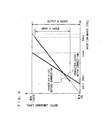
- FIG. 2 illustrates an input-output relationship in a conventional image processing apparatus.
- the detected maximum value Kmax and minimum value Kmin of the input video luminance signal are respectively extended to the maximum value MAX and a minimum value MIN of an output signal.
- the maximum value MAX is a maximum value of the dynamic range of the processing system (equivalent to 1023 in 10-bit processing), while the minimum value MIN is a minimum value of the dynamic range of the processing system (0, in general).
- Data at levels between the maximum value Kmax and the minimum value Kmin in the input video luminance signal are converted to data between the maximum value MAX and the minimum value MIN.
- a signal using the entire dynamic range of the processing system is output for each field, for example. Therefore, the contrast of the displayed image can be enhanced.
- the image processing apparatus according to the present embodiment does not use the maximum value Kmax and the minimum value Kmin as they are, but uses the corrected maximum value Lmax and the corrected minimum value Lmin, which are obtained by optimally correcting the above values in accordance with the scene on the screen, for correcting the gray scale.
- the method of correcting the gray scale in the present embodiment is described below.
- the corrected maximum value Lmax and the corrected minimum value Lmin are first calculated. How to calculate these corrected maximum value Lmax and corrected minimum value Lmin is described further below in detail. Then, as with the conventional method of correcting the gray scale, the input video luminance signal is corrected so that the corrected maximum value Lmax and the corrected minimum value Lmin are respectively extended to the maximum value MAX and the minimum value MIN of an output signal. This corresponds to the above-described operation of MAX/(Lmax - Lmin) ⁇ (L - Lmin).
- the corrected maximum value Lmax and the corrected minimum value Lmin are calculated in the present embodiment.
- a method of calculating the corrected maximum value Lmax and the corrected minimum value Lmin is specifically described below.
- histogram information is detected in an output signal of the low-pass filter 1.
- an amount of distribution n1 of a first part of a four-part split histogram is used as illustrated in FIG. 3(a) is exemplarily described.
- the maximum value correcting circuit 5 and the minimum value correcting circuit 6 Based on the histogram information detected by the histogram detecting circuit 2, the maximum value correcting circuit 5 and the minimum value correcting circuit 6 correct the maximum value Kmax and the minimum value Kmin output from the maximum value detecting circuit 3 and the minimum value detecting circuit 4, respectively.
- the minimum value correcting circuit 6 performs the correcting process so as to decrease the minimum value Kmin when the amount of distribution n1 of the first part of the four-part split histogram supplied as the histogram information by the histogram detecting circuit 2 is sufficiently large and, conversely, to increase the minimum value Kmin when n1 is sufficiently small.
- black can be enhanced when a distribution of black is small, while the gray scale of black can be kept when the distribution of black is large.
- This correcting method is illustrated in FIG. 3(b). In FIG.
- D f(n1)
- the histogram information is not restricted to the amount of distribution of the first and fourth parts of the four-part split histogram, and information other than the first and fourth can be referred to.
- the number of splits of the histogram is not restricted to four, and the histogram can be more finely split into, for example, eight or sixteen.
- the correcting process with the histogram distribution information may be performed only on the minimum value or the maximum value. Still further, for the purpose of keeping a ratio of each color of RGB after correction constant, color-difference signals may be additionally corrected in proportion to the correction of the video luminance signal.
- sufficient gray-scale correction can be performed by making use of the dynamic range of the processing system within a luminance level range as illustrated in FIG. 4, where a large distribution of black that occupies most of the screen is observed, even in the case as described where the detected maximum value Kmax approximately coincides with the maximum value MAX despite a dark scene.
- data between the corrected maximum value Lmax and the maximum value Kmax is output as the maximum value MAX, thereby causing white crush to occur.
- the amount of such data within that range is originally small. Therefore, by allowing this, better video display on the screen can be achieved as a whole.
- the correcting process in the present embodiment is performed such that, depending on the histogram information, the corrected minimum value Lmin may become smaller than the minimum value Kmin or the corrected maximum value Lmax may become larger than the maximum value Kmax. What this means is briefly described below.
- the maximum value Kmax and the minimum value Kmin detected by the maximum value detecting circuit 3 and the minimum value detecting circuit 4 are a maximum value and a minimum value, respectively, of a signal obtained after information at an isolation point is removed to some degree from the original input video luminance signal by the low-pass filter 2 and then further sampling at a predetermined sampling rate is performed. Therefore, in the actual input video luminance signal, video information originally required may exist even it is smaller than the minimum value Kmin illustrated in FIG. 4. The same goes for data that is larger than the maximum value Kmax. In such cases, with the conventional correcting method as illustrated in FIG. 2, for example, the data as described above is handled as data of the maximum value MAX or the minimum data MIN and, consequently, the gray-scale information is lost.
- the corrected minimum value Lmin is made smaller than the minimum value Kmin
- the video information originally required can be regarded although the corrected minimum value is smaller than the minimum value Kmin. Therefore, better image display can be performed in accordance with the scene.
- a correcting process based on the histogram distribution information is performed for extending a maximum value and a minimum value of an input video luminance signal to a dynamic range. Therefore, optimal correction effects can be obtained in accordance with the scene. Also, problems that occur in the above correcting process, such as black crush and white crush, can be mitigated. Thus, the gray scale of black and white levels and the contrast can both be satisfied.
- FIG. 5 illustrates the construction of an image processing apparatus according to a second embodiment of the present invention. Note that, in FIG. 5, components similar to those in the image processing apparatus illustrated in FIG. 1 are provided with the same reference numerals, and are not described herein.
- a concept of correcting the minimum value in the present embodiment is similar to that in the first embodiment.
- a bend point correcting circuit 11 a bend point of black extension is corrected based on the histogram distribution information.
- the principle of operation of a black extension correcting circuit 12 is described with reference to FIG. 6.
- the black extension correcting circuit 12 is supplied with the minimum value Lmin in a detection WINDOW output from the minimum value correcting circuit 6 for each field, a bend point Lio obtained by correcting a bend point initial value Kio in the bend point correcting circuit 11, and an input video luminance signal.
- the black extension correcting circuit 12 Based on the determination that a signal level smaller than the supplied Lmin does not exist, the black extension correcting circuit 12 extends a black level by bending a line representing a range below the bend point Lio, resulting in a line as illustrated in the drawing that represents characteristics after correction.
- This circuit can be achieved by hardware such as FPGA, or by software on a microcomputer, for example. Note that how to calculate the corrected minimum value Lmin is similar to that in the above-described first embodiment, and therefore is not described herein.
- the bend point correcting circuit 11 calculates an amount of correction D at the bend point as illustrated in FIG. 7, based on the distribution information detected by the histogram detecting circuit 2, such as the amount of distribution n1 of the first part of the four-part split histogram as illustrated in FIG. 3(a), for example.
- a function of D g(n1) should be optimized by considering the function in combination with the amount of correction of the minimum value in accordance with the display device.
- the input video luminance signal is corrected with the above operation.
- color-difference signals may be additionally corrected in proportion to the correction of the video luminance signal.
- the minimum value is detected for each field.
- the detected minimum value is corrected based on the luminance distribution of that field.
- the bend point for defining the range to be extended is also corrected based on the luminance distribution. Based on thus corrected minimum value and bend point, a process of correcting black extension is performed. Therefore, problems such as black crush that occurs at the time of correcting black extension can be mitigated, and the gray scale of the black level and the contrast can both be satisfied.
- FIG. 8 illustrates the construction of an image processing apparatus according to a third embodiment of the present invention. Note that, in FIG. 8, components similar to those in the image processing apparatus illustrated in FIG. 1 or FIG, 5 are provided with the same reference numerals, and are not described herein.
- a concept of correcting the maximum value in the present embodiment is similar to that in the first embodiment. Also, a concept of correcting the bend point is similar to that in the second embodiment.
- the principle of operation of a white extension correcting circuit 13 is now described with reference to FIG. 9.
- the white extension correcting circuit 13 is supplied with the maximum value Lmax in a detection WINDOW output from the maximum value correcting circuit 5 for each field, a bend point Lao obtained by correcting a bend point initial value in the bend point correcting circuit 11, and an input video luminance signal.
- the white extension correcting circuit 13 Based on the determination that a signal level larger than the supplied Lmax does not exist, the white extension correcting circuit 13 extends a white level by bending a line representing a range above the bend point Lao, resulting in a line as illustrated in the drawing that represents characteristics after correction.
- This circuit can be achieved by hardware such as FPGA, or by software on a microcomputer, for example. Note that how to calculate the corrected maximum value Lmax is similar to that in the above-described first embodiment, and therefore is not described herein.
- the bend point correcting circuit 11 calculates a bend point based on distribution information detected by the histogram detecting circuit 2, such as, for example, the amount of distribution n4 of the fourth part of the four-part split histogram as illustrated in FIG. 3(a).
- the input video luminance signal is corrected with the above operation.
- color-difference signals may be additionally corrected in proportion to the correction of the video luminance signal.
- the maximum value is detected for each field.
- the detected maximum value is corrected based on the luminance distribution of that field.
- the bend point for defining the range to be extended is also corrected based on the luminance distribution. Based on thus corrected maximum value and bend point, a process of correcting white extension is performed. Therefore, problems such as white crush that occurs at the time of correcting white extension can be mitigated, and the gray scale of the white level and the contrast can both be satisfied.
- FIG. 10 illustrates the construction of an image processing apparatus according to a fourth embodiment of the present invention.
- an input video luminance signal is corrected and is then output as an output luminance signal.
- the image processing apparatus according to the present embodiment is especially applied to a case where video color-difference signals are also corrected based on the output luminance signal for image display. Furthermore, this is also applied to a case where these corrected video luminance signal and video color-difference signals are converted into RGB signals for image display.
- the operation in the present embodiment is described below.
- the input video luminance signal is corrected by a gray-scale correcting circuit 14 so that a dynamic range is extended, such as black extension or white extension.
- a dynamic range is extended, such as black extension or white extension.
- the image processing apparatuses according to the first to third embodiments can be used as the gray-scale correcting circuit 14.
- gain of a luminance signal has been corrected
- gain of color-difference signals should also be corrected for each pixel in a similar manner to that of the luminance signal in order to keep a ratio of RGB after RGB signal conversion.
- an input color-difference signal level is detected.
- the color-difference signals U and V have values larger than a predetermined value, correction of the luminance signal is limited. This can avoid saturation of the corrected color-difference signals U and V and, furthermore, the RGB signals after RGB conversion.
- representing the magnitude of the input video color-difference signal is detected.
- may be either one of the components representing the magnitudes of the U and V signals which is larger, or attention may focus only on one of the components representing the magnitudes of the U and V signals.
- a corrected luminance signal limiter circuit 15 outputs an output video luminance signal based on an input video luminance signal, which is a signal Y1 before gray-scale correction, a signal Y2 after gray-scale correction output from the gray-scale correcting circuit 14, and the detection results of the color-difference signal level detecting circuit 16.
- the corrected luminance signal limiter circuit 15 outputs a signal Y2 after gray-scale correction as it is as the correction result Yout.
- the corrected luminance signal limiter circuit 15 outputs a signal at a level corresponding to the color-difference signal level
- color-difference signals Cout after correction color-difference signals Cin before correction x Yout / Y1, based on a ratio of the output video luminance signal Yout obtained by the image processing apparatus of the present embodiment and the input video luminance signal Y1. With this, the ratio of RGB is kept constant.
- output video luminance signal Yout and color-difference signals Cout (YUV) after correction are subjected to matrix conversion into RGB, any RGB alone does not go over the dynamic range of the signal processing system. Therefore, the above-described saturation problem can be avoided.
- the input-output relation in the corrected luminance signal limiter circuit 15 illustrated in FIG. 11 is set to a degree such that at least U and V signals are not saturated.
- the input-output relation in the corrected luminance signal limiter circuit 15 is as illustrated in FIG. 11. This is not meant to be restrictive. This input-output relation can be freely set as long as the above-described saturation problem can be avoided.
- the fourth embodiment in a case where a correcting process for extending the dynamic range of an input video luminance signal, such as black extension and white extension, is performed, when the results of this correction are used for correcting the color-difference signals, it is possible to avoid the color-difference signals after correction from being saturated to go over the dynamic range of the signal processing system. Furthermore, also when the corrected luminance signal and color-difference signals are converted into RGB signals for image display, it is possible to avoid the RGB signals from being saturated to go over the dynamic range of the signal processing system. Therefore, problems such as color crush due to luminance correction can be avoided, and degradation in display quality due to gray-scale correction can be prevented.
- a fifth embodiment is directed to a case where, for example, a maximum value of the input video luminance signal has to be obtained for gray-scale correction (by way of example, a case where the white extension correcting circuit 13 illustrated in FIG. 8 is used for gray-scale correction, etc.).
- a level of information such as white characters or the like included in the input video luminance signal is provisionally replaced by a level smaller than a maximum value of the original image, and then a maximum value is detected, thereby detecting the true maximum value of the original image.
- FIG. 12 is a block diagram illustrating the construction of an image processing apparatus according to the fifth embodiment of the present invention.
- the image processing apparatus includes a first maximum value detecting circuit 17, a histogram detecting circuit 18, a comparing circuit 19, a replacing circuit 20, a low-pass filter 21, and a second maximum value detecting circuit 22.
- the operation in the fifth embodiment is described below.
- the image processing apparatus is supplied with an input video luminance signal.
- This input video luminance signal is supplied to the first maximum value detecting circuit 17, the histogram detecting circuit 18, and the replacing circuit 20.
- the first maximum value detecting circuit 17 Based on the input video luminance signal, the first maximum value detecting circuit 17 detects a maximum value of a luminance level within a display area for each field or each frame. Then, luminance level values between the detected maximum value (hereinafter referred to as MAX value) and the MAX value - M are output to the histogram detecting circuit 18 and the replacing circuit 20.
- the value of M should be optimally set in accordance with the luminance width of white characters desired to be detected and, in general, is an integer of the range of 2 to 5.
- the histogram detecting circuit 18 detects luminance distribution information of the input video luminance signal, and then outputs, to the comparing circuit 19, an amount of distribution of the input video luminance signal at each luminance level from the MAX value to the MAX value - M supplied by the first maximum value detecting circuit 17.
- the comparing circuit 19 calculates a difference in the amount of distribution between the adjacent luminance levels, and when the difference in the amount of distribution is larger than a reference value W externally set, outputs information indicating as such.
- This detection of a large difference in the amount of distribution means detection of white characters such as subtitles. When an image including white characters such as subtitles is supplied, as illustrated in FIG. 13, distribution can be observed as having some luminance level width away from the original image information. In the present embodiment, by using such characteristics of the luminance levels of an image including white characters, the white characters are detected.
- Output from the histogram detecting circuit 18 are: an amount of distribution of the MAX value, an amount of distribution of (MAX value - 1), an amount of distribution of (MAX value - 2), and an amount of distribution of (MAX value - 3).
- the comparing circuit 19 calculates: an amount of distribution obtained by the amount of distribution of the MAX value - (MAX value - 1) (hereinafter, DEMAX1) ; an amount of distribution obtained by the amount of distribution of (MAX value - 1) - (MAX value - 2) (hereinafter, DEMAX2); and an amount of distribution obtained by the amount of distribution of (MAX value - 2) - (MAX value - 3) (hereinafter, DEMAX3) .
- DEMAX1 an amount of distribution obtained by the amount of distribution of the MAX value - (MAX value - 1) (hereinafter, DEMAX1)
- an amount of distribution obtained by the amount of distribution of (MAX value - 1) - (MAX value - 2) hereinafter, DEMAX2
- an amount of distribution obtained by the amount of distribution of (MAX value - 2) - (MAX value - 3) hereinafter, DEMAX3
- the difference represents white characters. If the above DEMAX3 is sufficiently large so as to go over the reference value W, this information is output from the comparing circuit 19 to the replacing circuit 20, where it is determined that the MAX value, the MAX value - 1, and the MAX value - 2 represent white character information, and the signal levels of these are replaced by sufficiently small levels.
- the levels for use in replacing can be 0 if gray-scale correction is not performed in the vicinity of black, and can be intermediate luminance levels if black correction is performed.
- An output of the replacing circuit 20 is supplied to the low-pass filter 21 for eliminating isolation point information, where the output is subjected to filter processing, and is then supplied to the second maximum value detecting circuit 22, where a maximum value of the displayed image is detected for each field or each frame. In this manner, an output maximum value signal is output. As such, white characters are detected and then replaced by those at sufficiently low luminance levels, and a maximum value is again detected, thereby enabling the true maximum value of the original image to be detected.
- the value should be optimally set depending on the luminance width of white characters desired to be detected.
- the reference value W should also be set depending on the luminance level of the white characters desired to be detected.
- the low-pass filter 21 may perform filter processing in only either one of horizontal and vertical directions, or may perform filter processing in both directions.
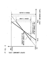
- gray-scale correction using the maximum value detected by the present embodiment is described with reference to FIG. 14.
- a bend point is optimally set, and correction is performed so that the detected MAX value becomes a maximum value of the dynamic range of the signal processing system.
- correction is performed so that a line can be drawn from the corrected maximum value to the bend point.
- a gray scale larger than the maximum value which would not have been originally used, can be effectively used. That is, as illustrated in FIG. 14, an input D range is extended to an output D range.
- white extension correction when the detected MAX value is larger than that of the original image due to white character information or the like, a gray scale to be extended becomes less, and therefore correction effects are reduced.
- the true maximum value of the original image can be detected. Therefore, by using the maximum value obtained by the present embodiment, it is possible to effectively operate gray-scale correction such as white extension as illustrated in FIG. 14.
- information such as white characters is determined based on the magnitude of the difference in the amount of distribution between adjacent luminance levels.
- information such as white characters can be determined based on the fact that the amount of distribution of the signal becomes 0 at a level of the MAX value - M.
- various schemes can be thought of. However, when it is determined whether the amount of distribution is 0, erroneous determination may occur due to information such as noise. Nevertheless, by making this determination based on the difference in the amount of distribution as in the present embodiment, more accurate determination is possible without being affected by noise or the like.
- information such as white characters is determined based on the amount of distribution of the luminance signal from the MAX value detected by the first maximum value detecting circuit 17 to a luminance level that is M levels away from the MAX value.
- determination of white characters, etc. is made irrespectively of the MAX value or the value of M, it is highly possible that information of the original image other than the white characters is erroneously determined as white characters.
- the value of M is preferably set to a value closer to the width of luminance distribution of the white characters to be detected.
- a sixth embodiment is directed to a case where, for example, a minimum value of an input video luminance signal has to be obtained for use in gray-scale correction (by way of example, a case where the black extension correcting circuit 12 illustrated in FIG. 5 is used for gray-scale correction, etc.)
- blanking included in the input video luminance signal or information such as black portions located at upper and lower portions of a cinema source is provisionally replaced by information at a level larger than a minimum value of the original image, and then a minimum value is detected, thereby detecting the true minimum value of the original image.
- FIG. 15 is a block diagram illustrating the construction of an image processing apparatus according to the sixth embodiment of the present invention. Note that, in FIG. 15, components identical to those of the fifth embodiment illustrated in FIG. 12 are provided with the same reference numerals, and are not described herein.
- an input video luminance signal is supplied to a first minimum value detecting circuit 23 and the histogram detecting circuit 18.
- the first minimum value detecting circuit 23 detects a minimum value within a display area for each field or each frame. At this time, the first minimum value detecting circuit 23 outputs, in addition to a minimum value (hereinafter, MIN value), values up to the MIN value + L to the histogram detecting circuit 18 and the replacing circuit 20.
- L is an integer of the range of 2 to 5.
- the histogram detecting circuit 18 detects luminance distribution information of the input video luminance signal, and then outputs an amount of distribution from the MIN value to the MIN value + L supplied by the first minimum value detecting circuit 23 to the comparing circuit 19.
- the comparing circuit 19 calculates a difference in the amount of distribution between adjacent luminance levels at luminance levels supplied by the histogram detecting circuit 18. If the calculation result is greatly varied from a reference value B that can be externally set, information indicating as such is output to the replacing circuit 20.
- This large variation means detection of a luminance level being unrelated to the information of the original image and representing blanking or black portions located at upper and lower portions of a cinema source. When information such as blanking is included in the video signal, this black information is distributed as having some luminance level width away from the original image.
- the comparing circuit 19 calculates: an amount of distribution obtained by the amount of distribution of the MIN value - (MIN value + 1) (hereinafter, DEMIN1); an amount of distribution obtained by the amount of distribution of (MIN value + 1) - (MIN value + 2) (hereinafter, DEMIN2); and an amount of distribution obtained by the amount of distribution of (MIN value + 2) - (MIN value + 3) (hereinafter, DEMIN3) .
- DEMIN1 an amount of distribution obtained by the amount of distribution of the MIN value - (MIN value + 1)
- DEMIN2 an amount of distribution obtained by the amount of distribution of (MIN value + 1) - (MIN value + 2)
- DEMIN3 an amount of distribution obtained by the amount of distribution of (MIN value + 2) - (MIN value + 3)
- the replacing circuit 20 determines that luminance level signals from the MIN value to the MIN value + 2 represent black information unrelated to the video such as blanking, and replaces them by those at any sufficiently large luminance levels.
- the levels for use in replacing can be a value of 1023 (10-bit processing) if gray-scale correction is not performed in the vicinity of white, and can be intermediate luminance levels if white correction is performed.
- An output of the replacing circuit 20 is supplied to the low-pass filter 21 for eliminating isolation point information, where the output is subjected to filter processing, and is then supplied to a second minimum value detecting circuit 24. In the second minimum value detecting circuit 24, a minimum value of the displayed image is detected for each field or each frame. In this manner, an output maximum value signal is output.
- black levels unrelated to the original image are detected and then replaced by sufficiently high luminance levels, and a minimum value is again detected, thereby enabling the true minimum value of the original image to be detected.
- the low-pass filter 21 may perform filter processing in only either one of horizontal and vertical directions, or may perform filter processing in both directions.
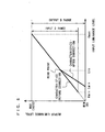
- gray-scale correction using the minimum value detected by the image processing apparatus of the present embodiment in the above' manner is described with reference to FIG. 17.
- a bend point is optimally set, and correction is performed so that the detected MIN value becomes a minimum value of the dynamic range of the signal processing system (0, in general).
- a gray scale from the bend point to the MIN value correction is performed so that a line can be drawn from the corrected minimum value (0, in general) to the bend point.
- a gray scale smaller than the maximum value which would not have been originally used, can be effectively used. That is, as illustrated in FIG. 17, an input D range is extended to an output D range.
- black extension correction when the detected MIN value is smaller than that of the original image due to erroneous detection of, for example, black in a blanking part, a gray scale to be extended becomes less, and therefore correction effects are reduced.
- the true minimum value of the original image can be detected. Therefore, even when the video signal includes black information such as blanking, the use of the minimum value obtained by the present embodiment enables gray-scale correction such as black extension as illustrated in FIG. 17 to effectively operate.
- FIG. 18 is a block diagram illustrating the construction of an image processing apparatus according to a seventh embodiment of the present invention.
- the image processing apparatus includes a maximum value detecting circuit 33, a cyclic-type filter 25, an APL (average luminance level) detecting circuit 30, an APL varied value detecting circuit 31, and a cyclic-type filter control circuit 32.
- the cyclic-type filter 25 includes an input through section 26, a filter processing section 27, an input interrupting section 28, and a selector 291. The operation in the seventh embodiment is described below.
- An input video luminance signal is supplied to the maximum value detecting circuit 33 and the APL detecting circuit 30.
- the maximum value detecting circuit 33 detects a maximum value of the video luminance signal within a display area for each field or each frame, and then outputs the detection result to the cyclic-type filter 25.
- the APL detecting circuit 30 detects an APL (average luminance level) of the video luminance signal within a display area for each field or each frame, and then outputs the detection result to the APL varied value detecting circuit 31.
- the APL varied value detecting circuit 31 detects for a variation in APL detected by the APL detecting circuit 30 for each field or each frame. Information about this variation in APL is output to the cyclic-type filter control circuit 32.
- the cyclic-type filter control circuit 32 performs two types of control, control of a cyclic coefficient of the filter processing section 27 in the cyclic type filter 25 and control of the selector 29.
- An APL varied value illustrated in FIG. 19 is represented as a ratio of the input video luminance signal with respect to the dynamic range. For example, in digital 10-bit processing, when the APL varied value is 50, it is represented as approximately 5% (50/1023).
- U and V which are arbitrary integers where U > V
- the cyclic-type filter control circuit 32 controls the selector 29 so that the input through section 26 is selected.
- the selector 29 is controlled so as to select the filter processing section 27.
- the selector 29 is controlled so as to select the input interrupting section 28.
- the cyclic-type filter control circuit 32 performs, in addition to the above control of a select signal, control of the cyclic coefficient of the filter processing section 27.
- FIG. 20 illustrates the structure of the filter processing section 27.
- the filter processing section 27 performs cyclic-type filtering on an output of the maximum value detecting circuit 33. Data is updated for each field by a vertical, synchronizing signal.
- the filter processing section 27 uses a cyclic coefficient k to multiply an input from the maximum value detecting circuit 33 by k, multiples a value that is fed back by (1 - k), and then adds both values together.
- the cyclic-type filter control circuit 32 controls the cyclic coefficient k so that it becomes large when the amount of APL variation is large and small when the amount of APL variation is small.
- An output of the filter processing section 27 is supplied to the input interrupting section 28 and the selector 29.
- the amount of APL variation is equal to or larger than U%, it can be thought that one scene has been changed to another non-successive scene. Therefore, information about any previous maximum value is completely disregarded, and only a current input from the maximum value detecting circuit 33 is selected for output as an output maximum value signal. As such, by completely disregarding the information about any previous maximum value, gray-scale correction that quickly follows the maximum value of the current image can be performed.
- the amount of APL variation is smaller than U% and equal to or larger than V%, it can be thought that the scene has been changed not drastically, but successively (such as panning by a camera) in consideration of previous information.
- an input from the filter processing section 27 is selected.
- the filter processing section 27 performs the control so that the cyclic coefficient becomes large when the amount of APL variation is large (a ratio of an input from the maximum value detecting circuit 33 is made large) and the cyclic coefficient becomes small when the amount of APL variation is small (a ratio of the input from the maximum value detecting circuit 33 is made small).
- a degree of how gray-scale correction follows becomes increased when the changes are relatively large, while the degree of how gray-scale correction follows becomes decreased when the changes are relatively small.
- a converting function for the amount of APL variation and the cyclic coefficient should be set in accordance with a display device.
- the input interrupting section 28 stores outputs of the filter processing section 27 while updating them as appropriate.
- the input interrupting section 28 stops updating of storage based on a control signal from the cyclic-type filter control circuit 32, and outputs the stored values to the selector.
- characteristic detection information of the displayed image such as the maximum value
- is output is controlled by the cyclic-type filter, or is not updated.
- threshold values U and V should be optimally set in accordance with the display device. Also, although the maximum value is taken as an example of the characteristic detection information, it is needless to say that the similar structure also goes for the minimum value.
- the image processing apparatus and the image processing method according to the present invention correct a gray scale of a signal displayed on a display or the like by optimally adjusting the gray scale in accordance with a video scene, thereby achieving image display of high image quality.
Landscapes
- Engineering & Computer Science (AREA)
- Physics & Mathematics (AREA)
- General Physics & Mathematics (AREA)
- Theoretical Computer Science (AREA)
- Multimedia (AREA)
- Signal Processing (AREA)
- Picture Signal Circuits (AREA)
- Facsimile Image Signal Circuits (AREA)
- Image Processing (AREA)
Abstract
Description
the minimum value correcting means obtains the corrected minimum value by correcting the minimum value detected by the minimum value detecting means in a decreasing direction based on the luminance distribution information detected by the histogram detecting means.
Claims (33)
- An image processing apparatus which corrects a gray scale by extending part of a luminance level range of an input video luminance signal to a dynamic range of a processing system, comprising:minimum value detecting means which detects a minimum value of the input video luminance signal;histogram detecting means which detects luminance distribution information of the input video luminance signal;minimum value correcting means which obtains a corrected minimum value by correcting the minimum value detected by the minimum value detecting means based on the luminance distribution information detected by the histogram detecting means; andluminance signal correcting means which extends the input video luminance signal so that the corrected minimum value obtained by the minimum value correcting means becomes a minimum value of the dynamic range of the processing system.
- The image processing apparatus according to claim 1, wherein
the luminance distribution information is an amount of distribution in a predetermined luminance range of a histogram distribution of the input video luminance signal. - The image processing apparatus according to claim 2, wherein
the predetermined luminance range is a luminance range in the histogram distribution corresponding to a minimum luminance part. - The image processing apparatus according to claim 1, wherein
the luminance signal correcting means corrects the input video luminance signal in a luminance range to be smaller than a predetermined bend point. - The image processing apparatus according to claim 4, further comprising
bend point correcting means which corrects the predetermined bend point in accordance with the luminance distribution information detected by the histogram detecting means. - The image processing apparatus according to claim 1, wherein
the minimum value detected by the minimum value detecting means is a minimum value of a signal obtained after the input video luminance signal is subjected to sampling or been passed through a low-pass filter, and
the minimum value correcting means obtains the corrected minimum value by correcting the minimum value detected by the minimum value detecting means in a decreasing direction based on the luminance distribution information detected by the histogram detecting means. - An image processing apparatus which corrects a gray scale by extending part of a luminance level range of an input video luminance signal to a dynamic range of a processing system, comprising:maximum value detecting means which detects a maximum value of the input video luminance signal;histogram detecting means which detects luminance distribution information of the input video luminance signal;maximum value correcting means which obtains a corrected maximum value by correcting the maximum value detected by the maximum value detecting means based on the luminance distribution information detected by the histogram detecting means; andluminance signal correcting means which extends the input video luminance signal so that the corrected maximum value obtained by the maximum value correcting means becomes a maximum value of the dynamic range of the processing system.
- The image processing apparatus according to claim 7, wherein
the luminance distribution information is an amount of distribution in a predetermined luminance range of a histogram distribution of the input video luminance signal. - The image processing apparatus according to claim 8, wherein
the predetermined luminance range is a luminance range in the histogram distribution corresponding to a maximum luminance part. - The image processing apparatus according to claim 7, wherein
the luminance signal correcting means corrects the input video luminance signal in a luminance range to be larger than a predetermined bend point. - The image processing apparatus according to claim 10, further comprising
bend point correcting means which corrects the predetermined bend point in accordance with the luminance distribution information detected by the histogram detecting means. - The image processing apparatus according to claim 7, wherein
the maximum value detected by the maximum value detecting means is a maximum value of a signal obtained after the input video luminance signal is subjected to sampling or been passed through a low-pass filter, and
the maximum value correcting means obtains the corrected maximum value by correcting the maximum value detected by the maximum value detecting means in an increasing direction based on the luminance distribution information detected by the histogram detecting means. - An image processing apparatus which corrects a gray scale by extending part of a luminance level range of an input video luminance signal to a dynamic range of a processing system, comprising:minimum value detecting means which detects a minimum value of the input video luminance signal;maximum value detecting means which detects a maximum value of the input video luminance signal;histogram detecting means which detects luminance distribution information of the input video luminance signal;minimum value correcting means which obtains a corrected minimum value by correcting the minimum value detected by the minimum value detecting means based on the luminance distribution information detected by the histogram detecting means;maximum value correcting means which obtains a corrected maximum value by correcting the maximum value detected by the maximum value detecting means based on the luminance distribution information detected by the histogram detecting means; andluminance signal correcting means which extends the input video luminance signal so that the corrected minimum value obtained by the minimum value correcting means and the corrected maximum value obtained by the maximum value correcting means respectively become a minimum value and a maximum value of the dynamic range of the processing system.
- An image processing apparatus which corrects a gray scale of a displayed image by correcting an input video luminance signal, comprising:luminance signal correcting means which corrects the input video luminance signal and outputs a video luminance signal after correction;color-difference signal level detecting means supplied with a video color-difference signal corresponding to the input video luminance signal for detecting a level of the video color-difference signal; andcorrection degree limiting means which limits a degree of correction of the input video luminance signal in the luminance signal correcting means based on the level of the video color-difference signal detected by the color-difference signal level detecting means, and produces an output as an output video luminance signal.
- The image processing apparatus according to claim 14,
wherein
the correction degree limiting means limits the degree of correction of the input video luminance signal so that, when the video color-difference signal is corrected in accordance with the degree of correction of the input video luminance signal, a video color-difference signal after correction are prevented from being saturated to go over the dynamic range of the processing system. - The image processing apparatus according to claim 15,
wherein
the correction degree limiting means limits the degree of correction of the input video luminance signal so that, when the output video luminance signal and the video color-difference signal after correction are converted into RGB signals, the RGB signals are prevented from being saturated to go over the dynamic range of the processing system. - The image processing apparatus according to claim 14, wherein
the correction degree limiting means limits the degree of correction of the input video luminance signal by weighting the input video luminance signal and the corrected video luminance signal in accordance with the level of the color-difference signal. - An image processing method of correcting a gray scale by extending part of a luminance level range of an input video luminance signal to a dynamic range of a processing system, comprising:a minimum value detecting step of detecting a minimum value of the input video luminance signal;a histogram detecting step of detecting luminance distribution information of the input video luminance signal;a minimum value correcting step of obtaining a corrected minimum value by correcting the minimum value detected in the minimum value detecting step based on the luminance distribution information detected in the histogram detecting step; anda luminance signal correcting step of extending the input video luminance signal so that the corrected minimum value obtained in the minimum value correcting step becomes a minimum value of the dynamic range of the processing system.
- An image processing method of correcting gray scale by extending part of a luminance level range of an input video luminance signal to a dynamic range of a processing system, comprising:a maximum value detecting step of detecting'a maximum value of the input video luminance signal;a histogram detecting step of detecting luminance distribution information of the input video luminance signal;a maximum value correcting step of obtaining a corrected maximum value by correcting the maximum value detected in the maximum value detecting step based on the luminance distribution information detected in the histogram detecting step; anda luminance signal correcting step of extending the input video luminance signal so that the corrected maximum value obtained in the maximum value correcting step becomes a maximum value of the dynamic range of the processing system.
- An image processing method of correcting a gray scale by extending part of a luminance level range of an input video luminance signal to a dynamic range of a processing system, comprising:a minimum value detecting step of detecting a minimum value of the input video luminance signal;a maximum value detecting step of detecting a maximum value of the input video luminance signal;a histogram detecting step of detecting luminance distribution information of the input video luminance signal;a minimum value correcting step of obtaining a corrected minimum value by correcting the minimum value detected in the minimum value detecting step based on the luminance distribution information detected in the histogram detecting step;a maximum value correcting step of obtaining a corrected maximum value by correcting the maximum value detected in the maximum value detecting step based on the luminance distribution information detected in the histogram detecting step; anda luminance signal correcting step of correcting the input video luminance signal so that the corrected minimum value obtained in the minimum value correcting step and the corrected maximum value obtained in the maximum value correcting step respectively become a minimum value and a maximum value of the dynamic range of the processing system.
- An image processing method of correcting a gray scale by extending part of a luminance level range of an input video luminance signal to a dynamic range of a processing system, comprising:a video luminance signal correcting step of correcting the input video luminance signal and outputting a video luminance signal after correction;a color-difference signal level detecting step of detecting a level of video color-difference signal that is supplied corresponding to the input video luminance signal; anda correction degree limiting step of limiting a degree of correction of the input video luminance signal in the luminance signal correcting step based on the level of the video color-difference signal detected in the color-difference signal level detecting step, and producing an output as an output video luminance signal.
- An image processing apparatus which detects a maximum luminance level of an original image in an input video luminance signal, comprising:first maximum value detecting means which detects in the input video luminance signal a maximum luminance level in a display area;histogram detecting means which detects an amount of distribution of the input video luminance signal at each luminance level in a luminance level range including the maximum luminance level detected by the first maximum value detecting means and a luminance level adjacent thereto;comparing means which determines, based on the amount of distribution detected by the histogram detecting means, whether the luminance level range includes information which is located at a luminance level away from the original image and is unrelated to the original image;replacing means which replaces, when the comparing means determines that the information unrelated to the original image is included, a luminance level with respect to the unrelated information in the input video luminance signal by a luminance level which unaffects detection of the maximum luminance level of the original image; andsecond maximum value detecting means which detects a maximum luminance level in an input video signal obtained after the luminance level with respect to the unrelated information is replaced by the replacing means.
- The image processing apparatus according to claim 22, wherein
the comparing means calculates a difference in an amount of distribution between adjacent luminance levels in the luminance level range, and when the difference in the amount of distribution is larger than a predetermined value, determines that the luminance level range includes the information unrelated to the original image. - The image processing apparatus according to claim 22,
wherein
the luminance level range includes two to five luminance levels. - An image processing apparatus which detects in an input video luminance signal a minimum luminance level of an original image, comprising:first minimum value detecting means which detects in the input video luminance signal a minimum luminance level in a display area;histogram detecting means which detects an amount of distribution of the input video luminance signal at each luminance level in a luminance level range including the minimum luminance level detected by the first minimum value detecting means and a luminance level adjacent thereto;comparing means which determines, based on the amount of distribution detected by the histogram detecting means, whether the luminance level range includes information which is located at a luminance level away from the original image and is unrelated to the original image;replacing means which replaces, when the comparing means determines that the information unrelated to the original image is included, a luminance level with respect to the unrelated information in the input video luminance signal by a luminance level which unaffects detection of the minimum luminance level of the original image; andsecond minimum value detecting means which detects a minimum luminance level in an input video signal obtained after the luminance level with respect to the unrelated information is replaced by the replacing means.
- The image processing apparatus according to claim 25, wherein
the comparing means calculates a difference in an amount of distribution between adjacent luminance levels in the luminance level range, and when the difference in the amount of distribution is larger than a predetermined value, determines that the luminance level range includes the information unrelated to the original image. - The image processing apparatus according to claim 25, wherein
the luminance level range includes two to five luminance levels. - An image processing apparatus for obtaining a maximum value signal suitable for dynamic gray-scale correction in motion pictures, comprising:APL detecting means which detects an average luminance level in a display area of an input video luminance signal;APL varied value detecting means which detects a varied value at the average luminance level detected by the APL detecting means;maximum value detecting means which detects a maximum luminance level in the display area of the input video luminance signal; andfilter means which controls the maximum luminance level detected by the maximum value detecting means in accordance with the varied value at the average luminance level detected by the APL varied value detecting means, and produces an output as the maximum value signal, whereinthe filter means outputs the maximum luminance level as it is when the varied value is larger than a first predetermined value, fixedly outputs a maximum luminance level that is an immediately previous output when the varied value is smaller than a second predetermined value, and outputs the maximum luminance level that follows in accordance with the varied value when the varied value is larger than the second predetermined value and smaller than the first predetermined value.
- An image processing apparatus for obtaining a minimum value signal suitable for dynamic gray-scale 'correction in motion pictures, comprising:APL detecting means which detects an average luminance level in a display area of an input video luminance signal;APL varied value detecting means which detects a varied value at the average luminance level detected by the APL detecting means;
minimum value detecting means which detects a minimum luminance level in the display area of the input video luminance signal; and
filter means which controls the minimum luminance level detected by the minimum value detecting means in accordance with the varied value at the average luminance level detected by the APL varied value detecting means, and produces an output as the minimum value signal, wherein
the filter means outputs the minimum luminance level as it is when the varied value is larger than a first predetermined value, fixedly outputs a minimum luminance level that is an immediately previous output when the varied value is smaller than a second predetermined value, and outputs the minimum luminance level that follows in accordance with the varied value when the varied value is larger than the second predetermined value and smaller than the first predetermined value. - An image processing method of detecting a maximum luminance level of an original image in an input video luminance signal, comprising:a first maximum value detecting step of detecting in the input video luminance signal a maximum luminance level in a display area;a histogram detecting step of detecting an amount of distribution of the input video luminance signal at each luminance level in a luminance level range including the maximum luminance level detected in the first maximum value detecting step and a luminance level adjacent thereto;a comparing step of determining, based on the amount of distribution detected in the histogram detecting step, whether the luminance level range includes information which is located at a luminance level away from the original image and is unrelated to the original image;a replacing step of replacing, when it is determined in the comparing step that the information unrelated to the original image is included, a luminance level with respect to the unrelated information in the input video luminance signal by a luminance level which unaffects detection of the maximum luminance level of the original image; anda second maximum value detecting step of detecting a maximum luminance level in an input video signal obtained after the luminance level with respect to the unrelated information is replaced in the replacing step.
- An image processing method of detecting a minimum luminance level of an original image in an input video luminance signal, comprising:a first minimum value detecting step of detecting in the input video luminance signal a minimum luminance level in a display area;a histogram detecting step of detecting an amount of distribution of the input video luminance signal at each luminance level in a luminance level range including the minimum luminance level detected in the first minimum value detecting step and a luminance level adjacent thereto;a comparing step of determining, based on the amount of distribution detected in the histogram detecting step, whether the luminance level range includes information which is located at a luminance level away from the original image and is unrelated to the original image;a replacing step of replacing, when it is determined in the comparing step that the information unrelated to the original image is included, a luminance level with respect to the unrelated information in the input video luminance signal by a luminance level which unaffects detection of the minimum luminance level of the original image; anda second minimum value detecting,step of detecting a minimum luminance level in an input video signal obtained after the luminance level with respect to the unrelated information is replaced in the replacing step.
- An image processing method for obtaining a maximum value signal suitable for dynamic gray-scale correction in motion pictures, comprising:an APL detecting step of detecting an average luminance level in a display area of an input video luminance signal;an APL varied value detecting step of detecting a varied value at the average luminance level detected in the APL detecting step;a maximum value detecting step of detecting a maximum luminance level in the display area of the input video luminance signal; anda filter step of controlling the maximum luminance level detected in the maximum value detecting step in accordance with the varied value at the average luminance level detected in the APL varied value detecting step, and producing an output as the maximum value signal, whereinthe filter step outputs the maximum luminance level as it is when the varied value is larger than a first predetermined value, fixedly outputs a maximum luminance level that is an immediately previous output when the varied value is smaller than a second predetermined value, and outputs the maximum luminance level that follows in accordance with the varied value when the varied value is larger than the second predetermined value and smaller than the first predetermined value.
- An image processing method for obtaining a minimum value signal suitable for dynamic gray-scale'correction in motion pictures, comprising:an APL detecting step of detecting an average luminance level in a display area of an input video luminance signal;an APL varied value detecting step of detecting a varied value at the average luminance level detected in the APL detecting step;a minimum value detecting step of detecting a minimum luminance level in the display area of the input video luminance signal; anda filter step of controlling the minimum luminance level detected in the minimum value detecting step in accordance with the varied value at the average luminance level detected in the APL varied value detecting step, and producing an output as the minimum value signal, whereinthe filter step outputs the minimum luminance level as it is when the varied value is larger than a first predetermined value, fixedly outputs a minimum luminance level that is an immediately previous output when the varied value is smaller than a second predetermined value, and outputs the minimum luminance level that follows in accordance with the varied value when the varied value is larger than the second predetermined value and smaller than the first predetermined value.
Applications Claiming Priority (5)
| Application Number | Priority Date | Filing Date | Title |
|---|---|---|---|
| JP2001165053 | 2001-05-31 | ||
| JP2001165053A JP3709981B2 (en) | 2001-05-31 | 2001-05-31 | Gradation correction apparatus and method |
| JP2001174666A JP2002369003A (en) | 2001-06-08 | 2001-06-08 | Image processing circuit and image processing method |
| JP2001174666 | 2001-06-08 | ||
| PCT/JP2002/003033 WO2002100093A1 (en) | 2001-05-31 | 2002-03-28 | Image processing apparatus and image processing method |
Publications (2)
| Publication Number | Publication Date |
|---|---|
| EP1359746A1 true EP1359746A1 (en) | 2003-11-05 |
| EP1359746A4 EP1359746A4 (en) | 2006-06-28 |
Family
ID=26616121
Family Applications (1)
| Application Number | Title | Priority Date | Filing Date |
|---|---|---|---|
| EP02707200A Withdrawn EP1359746A4 (en) | 2001-05-31 | 2002-03-28 | APPARATUS AND METHOD FOR IMAGE PROCESSING |
Country Status (5)
| Country | Link |
|---|---|
| US (1) | US7199840B2 (en) |
| EP (1) | EP1359746A4 (en) |
| CN (1) | CN1463534A (en) |
| CA (1) | CA2417169C (en) |
| WO (1) | WO2002100093A1 (en) |
Cited By (9)
| Publication number | Priority date | Publication date | Assignee | Title |
|---|---|---|---|---|
| EP1457924A1 (en) * | 2003-03-14 | 2004-09-15 | Seiko Epson Corporation | Image processing device, image processing method, and image processing program |
| EP1457925A1 (en) * | 2003-03-14 | 2004-09-15 | Seiko Epson Corporation | Image processing device, image processing method and image processing program |
| GB2425670A (en) * | 2005-04-28 | 2006-11-01 | Hitachi Ltd | Processing a video signal to perform black stretching in accordance with a luminance distribution |
| CN1305317C (en) * | 2004-12-27 | 2007-03-14 | 北京中星微电子有限公司 | Image brightness correcting method of video monitoring system |
| GB2431810A (en) * | 2005-04-28 | 2007-05-02 | Hitachi Ltd | Processing a video signal to perform black stretching and/or brightness correction in accordance with a luminance distribution |
| EP1818902A1 (en) * | 2006-02-13 | 2007-08-15 | Gigno Technology Co., Ltd. | Video display driving method of LCD |
| EP1768379A4 (en) * | 2004-06-18 | 2015-11-25 | Nikon Corp | Image processing device, image processing program, electronic camera, and image processing method |
| EP4277259A1 (en) | 2022-05-13 | 2023-11-15 | Sick Ag | Image capture and brightness adjustment |
| EP4411592A1 (en) | 2023-02-06 | 2024-08-07 | Sick Ag | Method for reading an optical code and optoelectronic code reader |
Families Citing this family (44)
| Publication number | Priority date | Publication date | Assignee | Title |
|---|---|---|---|---|
| JP3783645B2 (en) * | 2002-04-05 | 2006-06-07 | 株式会社日立製作所 | Contrast adjustment method, contrast adjustment circuit, and video display device using the same |
| KR100457534B1 (en) * | 2002-09-13 | 2004-11-17 | 삼성전자주식회사 | Apparatus and method for adjusting brightness and color temperature |
| TWI245557B (en) * | 2003-09-11 | 2005-12-11 | Matsushita Electric Industrial Co Ltd | Image compensation apparatus and method for the same |
| US7679627B2 (en) * | 2004-09-27 | 2010-03-16 | Qualcomm Mems Technologies, Inc. | Controller and driver features for bi-stable display |
| JP2006101421A (en) * | 2004-09-30 | 2006-04-13 | Toshiba Corp | Video signal processing circuit |
| CN1957603B (en) * | 2004-11-05 | 2011-02-09 | 松下电器产业株式会社 | Video signal conversion device, video display device |
| JP4788137B2 (en) * | 2004-12-09 | 2011-10-05 | 株式会社日立製作所 | Video display device |
| WO2006103835A1 (en) * | 2005-03-25 | 2006-10-05 | Mitsubishi Denki Kabushiki Kaisha | Image processing device, image display device, and image display method |
| CN100493142C (en) * | 2005-03-29 | 2009-05-27 | 松下电器产业株式会社 | Image display device and image display method |
| JP4580820B2 (en) * | 2005-06-02 | 2010-11-17 | オリンパスイメージング株式会社 | Image display device |
| JP4432933B2 (en) | 2005-07-08 | 2010-03-17 | セイコーエプソン株式会社 | Image display device and image display method |
| JP4687526B2 (en) | 2005-07-27 | 2011-05-25 | セイコーエプソン株式会社 | Moving image display device and moving image display method |
| JP4626497B2 (en) * | 2005-11-24 | 2011-02-09 | 株式会社日立製作所 | Video processing device and portable terminal device |
| US7894686B2 (en) * | 2006-01-05 | 2011-02-22 | Lsi Corporation | Adaptive video enhancement gain control |
| DE102006001075A1 (en) * | 2006-01-09 | 2007-07-12 | Carl Zeiss Ag | Electronic vision aid and electronic visual aid procedure |
| JP4325627B2 (en) * | 2006-02-21 | 2009-09-02 | ソニー株式会社 | Image display method, image display apparatus, and imaging apparatus |
| TWI347133B (en) * | 2006-04-20 | 2011-08-11 | Realtek Semiconductor Corp | Field balancing device and method |
| JP4210863B2 (en) * | 2006-07-06 | 2009-01-21 | セイコーエプソン株式会社 | Image processing system, display device, program, and information storage medium |
| KR20080015626A (en) * | 2006-08-16 | 2008-02-20 | 삼성전자주식회사 | Image processing apparatus and image processing method |
| CN101542562B (en) * | 2006-11-27 | 2011-05-18 | 松下电器产业株式会社 | Luminance level controller |
| US20080247665A1 (en) * | 2007-04-04 | 2008-10-09 | Silicon Integrated Systems Corp. | Method and apparatus for dynamic contrast enhancement |
| JP5270674B2 (en) * | 2007-06-29 | 2013-08-21 | トムソン ライセンシング | How to process the data for watermark data insertion, how to detect watermark data embedded in the data source, and how to detect the data generated by the watermark data embedding process. For detecting detected watermark data, apparatus for detecting watermark embedded in data source, and program storage medium |
| CN101547352B (en) * | 2008-03-26 | 2011-05-11 | 中华映管股份有限公司 | Image compression method and decompression method |
| JP5132470B2 (en) * | 2008-08-01 | 2013-01-30 | 三洋電機株式会社 | Image processing device |
| CN101742177B (en) * | 2008-11-11 | 2013-01-16 | 联咏科技股份有限公司 | Image filtering circuit, image processing circuit and image processing method using same |
| CN101655976B (en) * | 2009-09-10 | 2011-11-09 | 浙江工商大学 | Multi-view image brightness correcting method based on control point correction |
| KR20110043833A (en) * | 2009-10-22 | 2011-04-28 | 삼성전자주식회사 | Method and apparatus for determining dynamic range extension mode of digital camera using fuzzy rule |
| JP2011188391A (en) * | 2010-03-10 | 2011-09-22 | Sony Corp | Image processing apparatus, method and program |
| US8599318B2 (en) | 2010-05-21 | 2013-12-03 | Vixs Systems, Inc. | Contrast control device and method therefor |
| US8698961B2 (en) * | 2010-05-21 | 2014-04-15 | Vixs Systems, Inc. | Enhanced histogram equalization |
| EP4053786B1 (en) | 2010-11-23 | 2023-12-27 | Dolby Laboratories Licensing Corporation | Display of high dynamic range images on a local dimming display using bit depth reduction mapping metadata |
| JP6021465B2 (en) * | 2011-07-11 | 2016-11-09 | キヤノン株式会社 | Image processing apparatus and image processing apparatus control method |
| US9014504B2 (en) * | 2012-05-31 | 2015-04-21 | Apple Inc. | Systems and methods for highlight recovery in an image signal processor |
| JP5907938B2 (en) * | 2013-09-26 | 2016-04-26 | 京セラドキュメントソリューションズ株式会社 | Image forming apparatus and program |
| JP6241192B2 (en) * | 2013-10-18 | 2017-12-06 | 株式会社リコー | Image processing apparatus, image processing system, image processing method, program, and recording medium |
| US9460499B2 (en) * | 2014-05-30 | 2016-10-04 | Shenzhen Mindray Bio-Medical Electronics Co., Ltd. | Systems and methods for selective enhancement of a region of interest in an image |
| WO2016056787A1 (en) * | 2014-10-06 | 2016-04-14 | Samsung Electronics Co., Ltd. | Display device and method of controlling the same |
| JP6755701B2 (en) * | 2016-04-25 | 2020-09-16 | キヤノン株式会社 | Imaging device, display device and image processing device |
| JP6779695B2 (en) * | 2016-07-28 | 2020-11-04 | キヤノン株式会社 | Image processing device and its control method, display device |
| TWI588814B (en) * | 2016-08-18 | 2017-06-21 | 友達光電股份有限公司 | Driving method of pixel |
| JP6883971B2 (en) * | 2016-10-24 | 2021-06-09 | キヤノン株式会社 | Image processing equipment and image processing methods, programs, and storage media |
| US11823310B2 (en) * | 2018-09-07 | 2023-11-21 | Streem, Llc. | Context-aware selective object replacement |
| JP7271492B2 (en) * | 2020-12-11 | 2023-05-11 | シャープ株式会社 | Image processing device and image processing method |
| CN118865411A (en) * | 2024-06-26 | 2024-10-29 | 北京欣健隆科技有限公司 | A method for detecting printed secret codes |
Family Cites Families (17)
| Publication number | Priority date | Publication date | Assignee | Title |
|---|---|---|---|---|
| JPS63117589A (en) * | 1986-11-05 | 1988-05-21 | Mitsubishi Electric Corp | Video signal processing circuit |
| JPH02309871A (en) * | 1989-05-25 | 1990-12-25 | Canon Inc | Video signal correction device |
| US5339368A (en) * | 1991-11-21 | 1994-08-16 | Unisys Corporation | Document image compression system and method |
| JP2800633B2 (en) * | 1993-04-30 | 1998-09-21 | 富士ゼロックス株式会社 | Image coding device |
| JP3092397B2 (en) | 1993-06-22 | 2000-09-25 | 松下電器産業株式会社 | Imaging device |
| US5982926A (en) * | 1995-01-17 | 1999-11-09 | At & T Ipm Corp. | Real-time image enhancement techniques |
| JP3509448B2 (en) * | 1996-04-12 | 2004-03-22 | ソニー株式会社 | Video camera device, video signal processing device, color video signal level compression method and gradation conversion method |
| JP3549356B2 (en) | 1997-03-06 | 2004-08-04 | 松下電器産業株式会社 | Image luminance signal gradation correction device |
| JP2951910B2 (en) * | 1997-03-18 | 1999-09-20 | 松下電器産業株式会社 | Gradation correction device and gradation correction method for imaging device |
| US6236751B1 (en) * | 1998-09-23 | 2001-05-22 | Xerox Corporation | Automatic method for determining piecewise linear transformation from an image histogram |
| US7440612B2 (en) * | 1998-11-13 | 2008-10-21 | Sony Corporation | Image processing apparatus and method capable of correcting gradation of image data |
| US6825884B1 (en) * | 1998-12-03 | 2004-11-30 | Olympus Corporation | Imaging processing apparatus for generating a wide dynamic range image |
| TWI249630B (en) * | 1999-05-10 | 2006-02-21 | Matsushita Electric Industrial Co Ltd | Image display device and method for displaying image |
| JP3215388B2 (en) * | 1999-05-10 | 2001-10-02 | 松下電器産業株式会社 | Image display device and image display method |
| JP4376352B2 (en) | 1999-05-12 | 2009-12-02 | パナソニック株式会社 | Tone correction device |
| JP3430998B2 (en) * | 1999-11-08 | 2003-07-28 | 松下電器産業株式会社 | Image display device and image display method |
| TW518882B (en) * | 2000-03-27 | 2003-01-21 | Hitachi Ltd | Liquid crystal display device for displaying video data |
-
2002
- 2002-03-28 EP EP02707200A patent/EP1359746A4/en not_active Withdrawn
- 2002-03-28 CA CA002417169A patent/CA2417169C/en not_active Expired - Fee Related
- 2002-03-28 CN CN02801877A patent/CN1463534A/en active Pending
- 2002-03-28 US US10/343,060 patent/US7199840B2/en not_active Expired - Fee Related
- 2002-03-28 WO PCT/JP2002/003033 patent/WO2002100093A1/en not_active Ceased
Cited By (17)
| Publication number | Priority date | Publication date | Assignee | Title |
|---|---|---|---|---|
| US7313280B2 (en) | 2003-03-14 | 2007-12-25 | Seiko Epson Corporation | Image processing device, image processing method, and image processing program |
| EP1457925A1 (en) * | 2003-03-14 | 2004-09-15 | Seiko Epson Corporation | Image processing device, image processing method and image processing program |
| EP1457924A1 (en) * | 2003-03-14 | 2004-09-15 | Seiko Epson Corporation | Image processing device, image processing method, and image processing program |
| US7471343B2 (en) | 2003-03-14 | 2008-12-30 | Seiko Epson Corporation | Image processing device, image processing method, and image processing program |
| EP1768379A4 (en) * | 2004-06-18 | 2015-11-25 | Nikon Corp | Image processing device, image processing program, electronic camera, and image processing method |
| CN1305317C (en) * | 2004-12-27 | 2007-03-14 | 北京中星微电子有限公司 | Image brightness correcting method of video monitoring system |
| GB2425670B (en) * | 2005-04-28 | 2007-06-20 | Hitachi Ltd | Image processing apparatus |
| GB2431810B (en) * | 2005-04-28 | 2007-12-19 | Hitachi Ltd | Image processing apparatus |
| GB2431810A (en) * | 2005-04-28 | 2007-05-02 | Hitachi Ltd | Processing a video signal to perform black stretching and/or brightness correction in accordance with a luminance distribution |
| CN100428775C (en) * | 2005-04-28 | 2008-10-22 | 株式会社日立制作所 | image processing device |
| US7719619B2 (en) | 2005-04-28 | 2010-05-18 | Hitachi, Ltd. | Image processing apparatus |
| GB2425670A (en) * | 2005-04-28 | 2006-11-01 | Hitachi Ltd | Processing a video signal to perform black stretching in accordance with a luminance distribution |
| EP1818902A1 (en) * | 2006-02-13 | 2007-08-15 | Gigno Technology Co., Ltd. | Video display driving method of LCD |
| EP4277259A1 (en) | 2022-05-13 | 2023-11-15 | Sick Ag | Image capture and brightness adjustment |
| US12520047B2 (en) | 2022-05-13 | 2026-01-06 | Sick Ag | Recording and brightness adjustment of an image |
| EP4411592A1 (en) | 2023-02-06 | 2024-08-07 | Sick Ag | Method for reading an optical code and optoelectronic code reader |
| US12346768B2 (en) | 2023-02-06 | 2025-07-01 | Sick Ag | Method of reading an optical code and optoelectronic code reader |
Also Published As
| Publication number | Publication date |
|---|---|
| CA2417169A1 (en) | 2003-01-24 |
| US20040001165A1 (en) | 2004-01-01 |
| WO2002100093A1 (en) | 2002-12-12 |
| CN1463534A (en) | 2003-12-24 |
| US7199840B2 (en) | 2007-04-03 |
| CA2417169C (en) | 2009-04-28 |
| EP1359746A4 (en) | 2006-06-28 |
Similar Documents
| Publication | Publication Date | Title |
|---|---|---|
| CA2417169C (en) | Image processing apparatus and image processing method | |
| JP4011122B2 (en) | Image quality correction circuit for video signals | |
| JP4447035B2 (en) | Image processing device | |
| US6040860A (en) | Imaging apparatus for supplying images with rich gradation across the entire luminance range for all subject types | |
| US8260079B2 (en) | Video acquisition with processing based on ancillary data | |
| US8334932B2 (en) | Image processing device, image display device, and image processing method | |
| KR20000039639A (en) | Apparatus for improving image quality maintaining brightness of input image and method for doing the same | |
| KR20070113151A (en) | Image correction circuit, image correction method and image display device | |
| US7643180B2 (en) | Image processing and display apparatus and method for tone resolution expansion of digital images | |
| CN101075427B (en) | Image correction circuit, image correction method and image display | |
| US7688385B2 (en) | Video signal processing apparatus and method | |
| US20090304274A1 (en) | Image Processing Apparatus and Image Display Apparatus | |
| JP3208814B2 (en) | Video signal correction device | |
| JP3709981B2 (en) | Gradation correction apparatus and method | |
| JP4702132B2 (en) | Image processing apparatus, liquid crystal display apparatus, and color correction method | |
| JP4575963B2 (en) | Image processing device | |
| US7034896B2 (en) | Gradation correction apparatus | |
| US9019433B2 (en) | Image processing apparatus and method | |
| US7675573B2 (en) | Global motion adaptive system with motion values correction with respect to luminance level | |
| JP2008258925A (en) | Gamma correction circuit and gamma correction method | |
| US7471336B2 (en) | Global motion adaptive system with motion values correction with respect to luminance level | |
| JP2005077950A (en) | Histogram control image quality correction circuit | |
| US8564725B2 (en) | Video data processing apparatus and contrast correcting method | |
| JP2002369003A (en) | Image processing circuit and image processing method | |
| KR100679744B1 (en) | Error Diffusion Based on Gray Multiples for Smooth Gray Color Reproduction in Plasma Displays |
Legal Events
| Date | Code | Title | Description |
|---|---|---|---|
| PUAI | Public reference made under article 153(3) epc to a published international application that has entered the european phase |
Free format text: ORIGINAL CODE: 0009012 |
|
| 17P | Request for examination filed |
Effective date: 20030326 |
|
| AK | Designated contracting states |
Kind code of ref document: A1 Designated state(s): AT BE CH CY DE DK ES FI FR GB GR IE IT LI LU MC NL PT SE TR |
|
| RIC1 | Information provided on ipc code assigned before grant |
Ipc: G06T 5/40 20060101ALI20060315BHEP Ipc: H04N 1/407 20060101AFI20060315BHEP |
|
| A4 | Supplementary search report drawn up and despatched |
Effective date: 20060529 |
|
| 17Q | First examination report despatched |
Effective date: 20070910 |
|
| RAP1 | Party data changed (applicant data changed or rights of an application transferred) |
Owner name: PANASONIC CORPORATION |
|
| STAA | Information on the status of an ep patent application or granted ep patent |
Free format text: STATUS: THE APPLICATION HAS BEEN WITHDRAWN |
|
| 18W | Application withdrawn |
Effective date: 20141208 |