EP1363383A2 - Control circuit equipped with heating or cooling devices, particularly for direct current fans - Google Patents
Control circuit equipped with heating or cooling devices, particularly for direct current fans Download PDFInfo
- Publication number
- EP1363383A2 EP1363383A2 EP03010013A EP03010013A EP1363383A2 EP 1363383 A2 EP1363383 A2 EP 1363383A2 EP 03010013 A EP03010013 A EP 03010013A EP 03010013 A EP03010013 A EP 03010013A EP 1363383 A2 EP1363383 A2 EP 1363383A2
- Authority
- EP
- European Patent Office
- Prior art keywords
- control circuit
- heating
- fan
- circuit
- microprocessor
- Prior art date
- Legal status (The legal status is an assumption and is not a legal conclusion. Google has not performed a legal analysis and makes no representation as to the accuracy of the status listed.)
- Withdrawn
Links
Images




Classifications
-
- H—ELECTRICITY
- H02—GENERATION; CONVERSION OR DISTRIBUTION OF ELECTRIC POWER
- H02K—DYNAMO-ELECTRIC MACHINES
- H02K15/00—Processes or apparatus specially adapted for manufacturing, assembling, maintaining or repairing of dynamo-electric machines
- H02K15/12—Impregnating, moulding insulation, heating or drying of windings, stators, rotors or machines
- H02K15/125—Heating or drying of machines in operational state, e.g. standstill heating
-
- F—MECHANICAL ENGINEERING; LIGHTING; HEATING; WEAPONS; BLASTING
- F04—POSITIVE - DISPLACEMENT MACHINES FOR LIQUIDS; PUMPS FOR LIQUIDS OR ELASTIC FLUIDS
- F04D—NON-POSITIVE-DISPLACEMENT PUMPS
- F04D25/00—Pumping installations or systems
- F04D25/02—Units comprising pumps and their driving means
- F04D25/06—Units comprising pumps and their driving means the pump being electrically driven
- F04D25/0606—Units comprising pumps and their driving means the pump being electrically driven the electric motor being specially adapted for integration in the pump
- F04D25/0613—Units comprising pumps and their driving means the pump being electrically driven the electric motor being specially adapted for integration in the pump the electric motor being of the inside-out type, i.e. the rotor is arranged radially outside a central stator
-
- F—MECHANICAL ENGINEERING; LIGHTING; HEATING; WEAPONS; BLASTING
- F04—POSITIVE - DISPLACEMENT MACHINES FOR LIQUIDS; PUMPS FOR LIQUIDS OR ELASTIC FLUIDS
- F04D—NON-POSITIVE-DISPLACEMENT PUMPS
- F04D29/00—Details, component parts, or accessories
- F04D29/58—Cooling; Heating; Diminishing heat transfer
- F04D29/5813—Cooling the control unit
-
- F—MECHANICAL ENGINEERING; LIGHTING; HEATING; WEAPONS; BLASTING
- F04—POSITIVE - DISPLACEMENT MACHINES FOR LIQUIDS; PUMPS FOR LIQUIDS OR ELASTIC FLUIDS
- F04D—NON-POSITIVE-DISPLACEMENT PUMPS
- F04D29/00—Details, component parts, or accessories
- F04D29/58—Cooling; Heating; Diminishing heat transfer
- F04D29/582—Cooling; Heating; Diminishing heat transfer specially adapted for elastic fluid pumps
- F04D29/5853—Cooling; Heating; Diminishing heat transfer specially adapted for elastic fluid pumps heat insulation or conduction
-
- H—ELECTRICITY
- H02—GENERATION; CONVERSION OR DISTRIBUTION OF ELECTRIC POWER
- H02K—DYNAMO-ELECTRIC MACHINES
- H02K11/00—Structural association of dynamo-electric machines with electric components or with devices for shielding, monitoring or protection
- H02K11/20—Structural association of dynamo-electric machines with electric components or with devices for shielding, monitoring or protection for measuring, monitoring, testing, protecting or switching
- H02K11/25—Devices for sensing temperature, or actuated thereby
-
- H—ELECTRICITY
- H02—GENERATION; CONVERSION OR DISTRIBUTION OF ELECTRIC POWER
- H02K—DYNAMO-ELECTRIC MACHINES
- H02K11/00—Structural association of dynamo-electric machines with electric components or with devices for shielding, monitoring or protection
- H02K11/30—Structural association with control circuits or drive circuits
- H02K11/33—Drive circuits, e.g. power electronics
-
- H—ELECTRICITY
- H02—GENERATION; CONVERSION OR DISTRIBUTION OF ELECTRIC POWER
- H02K—DYNAMO-ELECTRIC MACHINES
- H02K7/00—Arrangements for handling mechanical energy structurally associated with dynamo-electric machines, e.g. structural association with mechanical driving motors or auxiliary dynamo-electric machines
- H02K7/14—Structural association with mechanical loads, e.g. with hand-held machine tools or fans
Definitions
- the present invention refers to a control circuit equipped with heating or cooling devices, particularly for direct current fans.
- the present invention has been provided to solve the forced ventilation problem in cooling systems, by means of direct current fans equipped with brushless motors.
- Object of the present invention is solving the above prior-art problems, allowing to produce ventilation systems with brushless motors equipped with internal electronics, also for different applications from the refrigerating ones, but characterised by low limit operating temperatures, such as for example aeronautical, criogenic, medical applications and the like, and campaign instruments to be used in cold climates.
- low limit operating temperatures such as for example aeronautical, criogenic, medical applications and the like
- campaign instruments to be used in cold climates.
- the "cold starting" characteristic is fundamental to allow using these fans as forced convection elements in quick heating systems.
- a further object of the invention is providing a quick defrosting system, to solve the ice formation problem when, together with low temperature, there is humidity (for example in refrigerating banks for ice creams).
- control circuit (1) of the present invention adapted to be used particularly for direct current fans (4), substantially comprises a basic circuit (5) equipped with a plurality of external wires (7) and containing:
- control circuit (1) of the invention further comprises at least one heating element (16) or at least one cooling element (not shown) installed in narrow contact with the microprocessor (9) and/or the active components (11, 13, 15).
- venting system would operate in the range between -30°C and -55°C: therefore, in its preferred application, it is enough that the concentrated heating system thermostats the microprocessor.
- the invention in a first preferred embodiment thereof, is composed of one or a plurality of heating elements (16), installed in narrow contact with the critical component or components.
- This thermal contact can be improved by using as propagating means a suitable thermally conductive and electrically insulating paste (not shown) that is commonly used in electronics.
- a layer of heat insulation (21) that in its preferred embodiment is a polyurethan foam
- a layer of heat insulation (21) that in its preferred embodiment is a polyurethan foam
- a suitable insulating layer a few hundreds of mW are enough to obtain the required result
- sensor systems are provided for detecting the temperature inside the thermostated cell, in which such sensor systems are adapted to close suitable reaction rings aimed to better control the temperature and/or to reduce the necessary power for heating.
- control circuit (1) adapted to work at high temperatures, instead of low temperatures.
- serpentines (not shown) would be inserted that enable the circulation of suitable cooling liquids, or suitably insulated heat pipes adapted to take the heat itself outside.
- Cooling fans (4) with brushless motors are largely manufactured in Asia in high numbers: therefore, given the low cost of these products in their standard version, it is extremely important that it is possible to recondition them with low intervention costs and as far as possible automatically. Among other things, this is one of the reasons that impair the above-mentioned arrangement with external electronics.
- control circuits (1) With this technique, the following types of control circuits (1) can be produced:
- This solution is particularly well adapted to not-excessive humidity conditions, so that the ice formation on blades (33) does not reach such thicknesses as to stall them or even more closes the spaces between one blade (33) and the other.
- a high-temperature (a few hundreds of degrees) radiating "grid” (39) will he used, to directly heat the blades (33) by radiance in a few seconds, thereby limiting the inserted energy and generating the immediate ice detachment.
Landscapes
- Engineering & Computer Science (AREA)
- Power Engineering (AREA)
- Mechanical Engineering (AREA)
- General Engineering & Computer Science (AREA)
- Microelectronics & Electronic Packaging (AREA)
- Physics & Mathematics (AREA)
- Thermal Sciences (AREA)
- Manufacturing & Machinery (AREA)
- Control Of Multiple Motors (AREA)
- Control Of Positive-Displacement Air Blowers (AREA)
- Control Of Motors That Do Not Use Commutators (AREA)
- Structures Of Non-Positive Displacement Pumps (AREA)
Abstract
Description
- A higher cost of fans equipped with induction motors, since the realisation of an asynchronous motor is more cumbersome, and mostly not yet automated in the current state of the art.
- A reduced working section for making air pass, with equal sizes of the venting system (or any fluid one is interested to pump), since also in its best execution an asynchronous motor anyway has much bigger sizes with respect to a brushless motor with the same performance.
- A lower efficiency, that is very bad, since it results in a power loss as heat, such event being rather dangerous inside a refrigerating apparatus.
- It is impossible to adjust the motor speed (which instead is often useful in modern refrigerating systems, to optimise their operation), unless very costly inverter systems are used to be externally applied.
- Since the electronics (and therefore any sensor) is completely missing inside the motor, it is not possible from the outside to know whether the system is operating or not, which instead is possible with a brushless motor. This too would be an extremely advantageous improvement for refrigerating systems, since when there is humidity, often the ice that is formed on the blades can get to completely block the motor.
- Figure 1 is a perspective view of an embodiment of a basic circuit without the device according to the present invention;
- Figure 2 is a perspective view of the circuit in Fig. 1 with a biased heater;
- Figure 3 is a perspective view of the circuit in Fig. 1 with an externally controlled heater;
- Figure 4 is a perspective view of the circuit in Fig. 1 with a heater and a temperature probe;
- Figure 5 is a perspective view of the circuit in Fig. 1 in its configuration with complete control;
- Figure 6 is a perspective view of the circuit in Fig. 1 in its configuration with complete internal control;
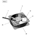
- Figure 7 is a side perspective view of a fan to which the device of the invention is applied;
- Figure 8 is a side perspective view of another fan to which the device of the invention is applied;
- Figure 9 is a bottom perspective view of a fan to which the device of the invention is applied, without an applied device; and
- Figure 10 is a bottom perspective view of the fan to which the device of the invention is applied, with an applied device.
- at least one microprocessor (9); and
- a plurality of active components (11), (13) and (15), like driving transistors, diodes and magnetic or optical sensors (for example Hall-effect type or photodiodes) .
- microprocessor (9) (typical minimum temperature, minus 30 °C)
- possible other active but slow (limit silica temperature, about minus 55 °C) components (11, 13, 15)
- Circuit (1) with biased heater (Fig. 2): it is characterised in that it has two wires (7) only, but the heater (16) that is reverse biased with respect to the fan (4) electronics. In this way, by directly supplying the system, it operates normally, and the electronic component (16) heating is solely assigned to its self-consumption and to the "coverage" (21) made of insulating material; by reversely supplying it when waiting, the fan (4) stops, but the heating elements (16) go on keeping the critical components (9, 11, 13, 15) under temperature. It is also possible to completely remove the supply during long stop periods, and then the system starting will occur with a first heating step lasting a few minutes and a following system starting.
- Circuit (1) with externally controlled heater (Fig. 3), with similar performance to the previous one but characterised in that it has at least three wires (7), since the connection with the heating elements (16) is directly taken outside.
- Circuit (1) with heater and temperature probe (Fig. 4), characterised in that it has an internal temperature probe (not shown) that is able to be read by a suitable external control electronics (not shown) in order to optimise the heating.
- Completely controlled circuit (Fig. 5), in order to reach the lowest temperatures, where also the other components cease to operate. In this case all active components (9, 11, 13, 15) are thermostated.
- Internal completely controlled circuit (Fig. 6), where the thermal control is always care of the internal microprocessor (9), and the active components (11), (13), (15) are concentrated in the same area (in such a way as to create a single thermostating point in any case) and a device is realised that is anyway with two wires (7) only, simplifying its installation by the end user.
- autonomously start at very low temperatures due to the internal electronics heating
- generate a quick system heating by using the defrosting grid (39) as a heater
- be used afterwards as a traditional venting system for cooling the circuit
- realise very high cost savings.
Claims (15)
- Control circuit (1), particularly for direct current fans (4), comprising a basic circuit (5) equipped with a plurality of external wires (7) and containing:characterised in that it further comprises at least one heating element (16) installed in narrow contact with said microprocessor (9) and/or said active components (11, 13, 15).at least one microprocessor (9); anda plurality of active components (11), (13) and (15), like driving transistors, diodes and magnetic or optical sensors (for example Hall-effect type or photodiodes);
- Control circuit (1) according to Claim 1, characterised in that at least one heating element (16) is composed of electric resistances welded onto the basic circuit (5) near the components (9), (11, 13, 15) to be heated.
- Control circuit (1) according to Claim 1, characterised in that it further comprises a heat insulating layer (21) whose purpose is thermally insulating the component (9), (11, 13,15) to be thermostated from the external environment, and reducing the necessary power for control.
- Control circuit (1) according to Claim 3, characterised in that said heat insulating layer (21) is made of a polyurethane foam.
- Control circuit (1) according to Claim 1, characterised in that it further comprises a thermally conductive and electrically insulating paste as propagation means adapted to improve the thermal contact between heating elements (16) and components (9, 11, 13, 15) to be heated.
- Control circuit (1) according to Claim 3 or 4, characterised in that it further comprises sensor systems to detect the temperature inside said heat insulating layer (21), said sensor systems being adapted to close corresponding reaction rings in order to perform a temperature check and/or a reduction of the necessary power for heating.
- Control circuit (1) according to Claim 1, characterised in that said circuit (1) is equipped with at least three wires (7), the connection for said heating elements (16) being taken directly outside.
- Control circuit (1) according to Claim 1, characterised in that said circuit (1) further has an internal temperature probe that is able to be read by an external control electronics to optimise heating.
- Control circuit (1) according to Claim 1, characterised in that the thermal control is always care of said internal microprocessor (9), and active components (11, 13, 15) are concentrated in the same area, in order to create in any case a single thermostating point.
- Control circuit (1), particularly for direct current fans (4), comprising a basic circuit (5) equipped with a plurality of external wires (7) and containing:characterised in that it further comprises at least one cooling element installed in narrow contact with said microprocessor (9) and/or said active components (11, 13, 15).at least one microprocessor (9); anda plurality of active components (11), (13) and (15), like driving transistors, diodes and magnetic or optical sensors (for example Hall-effect type or photodiodes);
- Control circuit (1) according to Claim 10, characterised in that at least one cooling element is composed of a serpentine with refrigerating substances circulation.
- Control circuit (1) according to Claim 10, characterised in that at least one cooling element is composed of a suitably-insulated heat pipe adapted to take heat outside.
- Direct current fan (4), particularly for refrigerator applications, characterised in that it comprises a control circuit according to any one of Claims 1 to 9, and in that it is further equipped with a further defrosting element (35) adapted to remove ice formations on blades (33) of said fan (4).
- Fan (4) according to Claim 13, characterised in that said defrosting element (35) is composed of a heating band (35) external to the case (37) of said fan (4) and thermally insulated from the outside.
- Fan (4) according to Claim 13 or 14, characterised in that it is further equipped with a high-temperature radiating grid (39) adapted to directly heat the blades (33) of the fan (4) by radiance, limiting the inserted energy and making ice immediately detach.
Applications Claiming Priority (2)
| Application Number | Priority Date | Filing Date | Title |
|---|---|---|---|
| ITTO20020419 | 2002-05-17 | ||
| IT2002TO000419A ITTO20020419A1 (en) | 2002-05-17 | 2002-05-17 | CONTROL CIRCUIT EQUIPPED WITH HEATING OR COOLING DEVICES, IN PARTICULAR FOR DIRECT CURRENT FANS. |
Publications (2)
| Publication Number | Publication Date |
|---|---|
| EP1363383A2 true EP1363383A2 (en) | 2003-11-19 |
| EP1363383A3 EP1363383A3 (en) | 2006-07-12 |
Family
ID=27639087
Family Applications (1)
| Application Number | Title | Priority Date | Filing Date |
|---|---|---|---|
| EP03010013A Withdrawn EP1363383A3 (en) | 2002-05-17 | 2003-05-02 | Control circuit equipped with heating or cooling devices, particularly for direct current fans |
Country Status (2)
| Country | Link |
|---|---|
| EP (1) | EP1363383A3 (en) |
| IT (1) | ITTO20020419A1 (en) |
Cited By (4)
| Publication number | Priority date | Publication date | Assignee | Title |
|---|---|---|---|---|
| WO2014056662A1 (en) * | 2012-10-08 | 2014-04-17 | Ebm-Papst Mulfingen Gmbh & Co. Kg | Wall ring with wall ring heating element for axial fans |
| WO2014056677A1 (en) * | 2012-10-08 | 2014-04-17 | Ebm-Papst Mulfingen Gmbh & Co. Kg | Wall ring for an axial fan |
| EP3875778A1 (en) * | 2020-03-06 | 2021-09-08 | Konvekta Aktiengesellschaft | Improved air treatment system and fan unit for same |
| CN116877492A (en) * | 2023-02-08 | 2023-10-13 | 上海六盛电机有限公司 | DC brushless fan for deep cooling refrigerator |
Family Cites Families (7)
| Publication number | Priority date | Publication date | Assignee | Title |
|---|---|---|---|---|
| GB2177880A (en) * | 1985-07-17 | 1987-01-28 | Meei Lii Shiuh | A heating device for a fan |
| JPH0442784A (en) * | 1990-06-04 | 1992-02-13 | Fukoku Co Ltd | Ultrasonic motor with temperature regulator |
| JP2902897B2 (en) * | 1993-04-28 | 1999-06-07 | 三菱電機株式会社 | Servomotor |
| JP3886697B2 (en) * | 1999-04-27 | 2007-02-28 | アイシン・エィ・ダブリュ株式会社 | Drive device |
| JP3426538B2 (en) * | 1999-05-28 | 2003-07-14 | 株式会社巴技術研究所 | Electric actuator for valve drive |
| GB2355860A (en) * | 1999-10-28 | 2001-05-02 | Delphi Tech Inc | Heat shielding electric motor or generator electric components |
| DE10004188A1 (en) * | 2000-02-01 | 2001-08-09 | Siemens Ag | Electric drive arrangement with at least one electric machine - has data on electric machine revs, air humidity, and volume flow-rate of cooling medium, transmitted to control device for setting up optimal thermal state for drive |
-
2002
- 2002-05-17 IT IT2002TO000419A patent/ITTO20020419A1/en unknown
-
2003
- 2003-05-02 EP EP03010013A patent/EP1363383A3/en not_active Withdrawn
Cited By (7)
| Publication number | Priority date | Publication date | Assignee | Title |
|---|---|---|---|---|
| WO2014056662A1 (en) * | 2012-10-08 | 2014-04-17 | Ebm-Papst Mulfingen Gmbh & Co. Kg | Wall ring with wall ring heating element for axial fans |
| WO2014056677A1 (en) * | 2012-10-08 | 2014-04-17 | Ebm-Papst Mulfingen Gmbh & Co. Kg | Wall ring for an axial fan |
| CN104736852A (en) * | 2012-10-08 | 2015-06-24 | 依必安-派特穆尔芬根股份有限两合公司 | Wall ring for an axial fan |
| CN104736852B (en) * | 2012-10-08 | 2017-05-10 | 依必安-派特穆尔芬根股份有限两合公司 | Wall rings for axial fans with wall ring heaters |
| US9970458B2 (en) | 2012-10-08 | 2018-05-15 | Ebm-Papst Mulfingen Gmbh & Co. Kg | Wall ring with wall ring heating element for axial fans |
| EP3875778A1 (en) * | 2020-03-06 | 2021-09-08 | Konvekta Aktiengesellschaft | Improved air treatment system and fan unit for same |
| CN116877492A (en) * | 2023-02-08 | 2023-10-13 | 上海六盛电机有限公司 | DC brushless fan for deep cooling refrigerator |
Also Published As
| Publication number | Publication date |
|---|---|
| ITTO20020419A1 (en) | 2002-08-16 |
| EP1363383A3 (en) | 2006-07-12 |
Similar Documents
| Publication | Publication Date | Title |
|---|---|---|
| CN109662360A (en) | A kind of isothermic garment for heating and freezing using power supply | |
| US9671172B2 (en) | Motor with cooled rotor | |
| TW200530566A (en) | Method for detecting temperature of semiconductor element and semiconductor power converter | |
| CN110112111A (en) | Intelligent power module, electric-controlled plate and air conditioner | |
| KR200467728Y1 (en) | Heat dissipation device with multiple heat conducting pipes | |
| EP3711996B1 (en) | Cooling system and method for motor and controller | |
| EP1363383A2 (en) | Control circuit equipped with heating or cooling devices, particularly for direct current fans | |
| CN104792060B (en) | Heat abstractor, motor and air conditioner | |
| CN204538007U (en) | The heat abstractor of power device | |
| CN108679876A (en) | A kind of semiconductor cooling device | |
| CN116867249A (en) | Heat dissipation methods and related equipment | |
| CN213207947U (en) | Temperature control heat dissipation structure of electric heating furnace | |
| CN108489047A (en) | Intelligent power module component, air conditioner and its control method | |
| CN114171473A (en) | Power device, control method thereof, frequency conversion system and air conditioning equipment | |
| CN109520090B (en) | Cooling device heat dissipation control method and device, cooling device and storage medium | |
| CN119860580A (en) | Temperature value calculation method, air conditioner control method and air conditioner | |
| JP5310621B2 (en) | Air conditioner | |
| JP2014096886A (en) | Power supply device | |
| US20220361364A1 (en) | Method for cooling a device such as an electric motor drive or a general power converter and device such as an electric motor drive or a general power converter for performing the cooling method | |
| CN119452502A (en) | Heat dissipation device, vehicle and heat dissipation control method | |
| CN111051792A (en) | PTC heater | |
| JP3320305B2 (en) | Heater device | |
| CN222964201U (en) | Refrigeration equipment | |
| KR20060020788A (en) | Enclosed Computer Chiller | |
| CN202195896U (en) | Electronic temperature controlled switch temperature sensor assembly |
Legal Events
| Date | Code | Title | Description |
|---|---|---|---|
| PUAI | Public reference made under article 153(3) epc to a published international application that has entered the european phase |
Free format text: ORIGINAL CODE: 0009012 |
|
| AK | Designated contracting states |
Kind code of ref document: A2 Designated state(s): AT BE BG CH CY CZ DE DK EE ES FI FR GB GR HU IE IT LI LU MC NL PT RO SE SI SK TR |
|
| AX | Request for extension of the european patent |
Extension state: AL LT LV MK |
|
| RAP1 | Party data changed (applicant data changed or rights of an application transferred) |
Owner name: FANDIS S.P.A. |
|
| PUAL | Search report despatched |
Free format text: ORIGINAL CODE: 0009013 |
|
| AK | Designated contracting states |
Kind code of ref document: A3 Designated state(s): AT BE BG CH CY CZ DE DK EE ES FI FR GB GR HU IE IT LI LU MC NL PT RO SE SI SK TR |
|
| AX | Request for extension of the european patent |
Extension state: AL LT LV MK |
|
| AKX | Designation fees paid | ||
| REG | Reference to a national code |
Ref country code: DE Ref legal event code: 8566 |
|
| STAA | Information on the status of an ep patent application or granted ep patent |
Free format text: STATUS: THE APPLICATION IS DEEMED TO BE WITHDRAWN |
|
| 18D | Application deemed to be withdrawn |
Effective date: 20061201 |