EP1369526A1 - Calandre et procédé de calandrage - Google Patents
Calandre et procédé de calandrage Download PDFInfo
- Publication number
- EP1369526A1 EP1369526A1 EP03012360A EP03012360A EP1369526A1 EP 1369526 A1 EP1369526 A1 EP 1369526A1 EP 03012360 A EP03012360 A EP 03012360A EP 03012360 A EP03012360 A EP 03012360A EP 1369526 A1 EP1369526 A1 EP 1369526A1
- Authority
- EP
- European Patent Office
- Prior art keywords
- arrangement according
- roller
- jacket
- counter
- pressure
- Prior art date
- Legal status (The legal status is an assumption and is not a legal conclusion. Google has not performed a legal analysis and makes no representation as to the accuracy of the status listed.)
- Granted
Links
Images


Classifications
-
- D—TEXTILES; PAPER
- D21—PAPER-MAKING; PRODUCTION OF CELLULOSE
- D21G—CALENDERS; ACCESSORIES FOR PAPER-MAKING MACHINES
- D21G1/00—Calenders; Smoothing apparatus
- D21G1/006—Calenders; Smoothing apparatus with extended nips
Definitions
- the invention relates to a calender arrangement with a Shoe roll, which has a circumferential jacket, the with the help of a pressure shoe towards a counter roller is resilient.
- the invention further relates to a method for satinizing a material web in one Breitnip, which is between a circumferential coat and a counter roll is formed, taking the jacket with the help of a pressure shoe attached to the inside of the coat bears against the counter roller.
- Such a calender arrangement and such Methods are for example from DE 299 02 436 U1 or DE 299 02 451 U1 known.
- the shoe roll forms together with the counter roll a nip through which a material web, in particular a paper or cardboard web, can be performed.
- the mantle of the runner is relatively compliant, so that it is about one predetermined peripheral portion to the shape of the counter roll adapts. So that the length of the nip in the direction of movement increased.
- Such a nip will also Called "Breitnip".
- the enlargement of the nip has that Advantage that one with the same web speed Treatment time can be longer in the wide nip than in a conventional nip that is between two Rolling is formed. This is done with the same force the compressive stress in the wide nip is lower, so that the compression of the material web is correspondingly smaller is held.
- the jacket has the required flexibility, it is usually made of a plastic. In some cases it is not desirable for the Jacket gets direct contact with the counter roller.
- plastics are only thermally limited resilient. If you heat the counter roller, then you have to them to the required amount of heat in the wide nip to be able to feed in, have surface temperatures, which can be higher than 200 ° C. This is not a problem as long as a web of material passes through the nip is led. The web of material then separates them Counter roll from the jacket.
- the invention has for its object a system to prevent the jacket on the counter roller.
- This task is the beginning of a calender arrangement mentioned type in that the pressure shoe has a support surface, the width of which in one direction is changeable parallel to the axis of the counter roller.
- the width of the pressure shoe is then adjusted so that the jacket only in the area of the material web against the Counter roll is pressed. However, this is the area the material web between the jacket and the counter roll, so that there is direct contact between the coat and the counter roller can be avoided. In the Areas outside the material web lack support of the jacket through the pressure shoe. Without these But the coat doesn't get as much support anymore approximated to the counter roller that the danger of a thermal overload exists. The coat will held at its axial ends anyway, so that the jacket is conical starting from the ends of the pressure shoe runs away from the counter roll.
- the concept of "Counter roller” is to be understood generally here. In the in most cases, the backing roller is actually through formed a cylindrical body.
- the "counter roller” can also be used as an abutment in other ways be designed for the jacket, for example as Ribbon or coat.
- the counter roller is preferably heated. If introduces heat into the wide nip via the counter roller, then you can heat the material web, which is also positive on the treatment of the material web, in particular the surface properties of a paper or Cardboard web, affects.
- the width of the support surface is preferably dependent changeable from the width of a material web, the one wide nip between the jacket and the counter roller passes. This provides a criterion based on which you can adjust the width of the support surface can.
- the change in the width of the support surface is a relatively simple measure, so that one without major renovation work in different ways can satinize wide material webs.
- the support surface preferably has one in the direction Limitation movable parallel to the axis of the counter roller on.
- the support surface can with the limitation in mind stop being outside of the limit mechanical Support completely lacking. But you can also imagine the support surface through a pressurized standing pad of a hydraulic fluid formed becomes. In this case, the limit is limited this pressure pad. If the limit moved then the axial length of this pressure pad just bigger or smaller.
- the limitation is preferably a cross bar formed between two sealing strips which extend parallel to the axis of the counter roll.
- the two sealing strips are in the direction of movement the material web immovable in relation to the Jacket arranged. You define in the direction of movement the web of material the beginning and end of a zone, in which is pressurized. The setting in the width direction then occurs through the movement of the Sealing strip.
- the cross bar can preferably be moved in a room, which is closed at the front.
- the frontal closure then forms a limit for the Movement of the cross bar.
- the front end connects doing the two sealing strips, which is a special one great mechanical stability allowed.
- the space preferably has a pressure medium feed on. Accordingly, the room can be pressurized become. This pressure then builds up a counter pressure the pressure that exists in the support surface. Even if the pressure in the room is not as big, you can balance the forces on the cross bar at least partially. It is then easier to attach the cross bar to the desired position.
- the cross bar be provided in the manner of a U with two legs that are sealingly guided on the sealing strips.
- the cross bar then forms one with the two legs Drawer between the sealing strips or outside the sealing strips can be moved to the axial Change the length of the support surface.
- the sealing strips preferably have a pressure arrangement on.
- the sealing strips are so with a certain Force pressed against the coat from the inside, so that at least in the axial direction a seal between the Sealing strips and the surrounding jacket can be achieved can, which allows the required in the support surface Building pressure.
- the pressure arrangement can be coupled to the cross bar so that the sealing strips pressed against the jacket only in one area be limited by the cross bar. Outside the jacket can then move away from the counter roll, because he is no longer from the sealing strips is sufficiently supported.
- the pressure shoe is on at least one axial end with an extension element renewable. So it is only possible to extend the pressure shoe in discrete steps or shorten it. Attaching an extension element on the pressure shoe is a relatively simple one Measure so that you no longer have the disadvantage of one Accept continuous extension or shortening can.
- extension element from a non-active position in which there is a distance has to the jacket, shifted to an active position in which it lies against the inside of the coat. You get there an extension or a shortening of the Pressure shoe simply by having an extension element emotional. The movement or relocation of one Extension element is relatively easy too realize. There are no major renovations required. In particular, it can be provided that Relocation of the extension element a drive available is so that you can control the relocation from the outside can.
- the inactive position is preferably inside of the jacket arranged.
- the active position is anyway arranged inside the jacket.
- the relocation movement then finds completely inside the mantle instead, so that you can carry through the coat or does not have to realize its end faces.
- the extension element is between the inactive and the active position on a ramp movable. So you arrange one inside the coat Carrier ramped at predetermined sections is trained. If you have an extension element moves along this ramp, then it approaches further on the coat or it moves away from him. With the help of the ramp, the individual positions can be the extension elements set relatively easily. Because of the slope of the ramp, it is too possible with relatively low forces that lead to movement of the extension element exercised along the ramp can be correspondingly large forces towards to generate on the backing roll when the extension element is in its active position. These powers are only required as holding forces during operation.
- the ramp preferably runs in the axial direction. In There is usually sufficient space in the axial direction to disposal. You can then drive in the axial direction let act on the extension elements.
- an axially arranged further outside Extension element a longer foot than an extension element arranged axially further inside having. So you can all extension elements Arrange on the ramp. An axially outward lying extension element is then over the corresponding longer foot in the same radial position moves like an axially inner extension element.
- the ramp is inclined relative to a direction that on a press level through the wide nip between the Jacket and the counter roller is vertical.
- the press level is basically spanned by the axis of the Counter roller and the central axis of the jacket of the shoe roller.
- the extension elements moved and moved parallel to a radial direction this way up or down the ramp. This Design is advantageous if in the axial direction not enough space is available.
- Each extension element preferably has one Lubrication on.
- the lubrication can be hydrodynamic his.
- the extension elements and the pressure shoe so designed that the lubricating oil adhering to the jacket during movement of the jacket relative to the pressure shoe a lubricating film between the pressure shoe or the extension element or elements and can form the coat.
- the extension elements then basically have the same cross-sectional shape like the pressure shoe. If you have a hydrostatic Provides lubrication, then both the pressure shoe as well as the individual extension elements each with a pressure connection for the lubricant be provided. Each extension element can then one have their own pressure bag over which the lubricant can be fed.
- the pressure shoe and each extension element a rounding on its axial outside on. This will damage the jacket of avoid inside at the point where the support ceases through the pressure shoe. You avoid one sharp edge, so that the life of the jacket is extended becomes.
- each extension element on its axial inside there is a matching rounding Forming has. You get, so to speak a "seamless" surface of the pressure shoe.
- the task is in a method of the aforementioned Art solved in that depending on the width of the material web, the axial limitation of a Support surface of the pressure shoe changed.
- the width of a pressure pocket changed, which forms the support surface.
- This hydraulic fluid has a larger one or a smaller axial length act on the jacket the axial treatment length also changes.
- the change in the width of the pressure bag, more precisely said its axial length is relatively easy to carry out.
- a calender arrangement 1 according to FIGS. 1 and 2 has a shoe roller 2 with a counter roller 3 Breitnip 4 forms, through which a material web 5, in present example is a paper or cardboard web can be to get there with increased pressure and increased Temperature to be applied.
- a material web 5 in present example is a paper or cardboard web can be to get there with increased pressure and increased Temperature to be applied.
- the counter roll 3 For the heightened Temperature is the counter roll 3 with only one provided schematically illustrated heater 6.
- the heating of the counter roll 3 can also be done on others Way, such as by feeding a hot Liquid or vapor.
- the shoe roller 2 has a roller shell 7 which with the help of a pressure shoe 8 in the direction of the counter roller 3 is pressed.
- the pressure shoe 8 has one Contact side 9 with a curvature that matches the curvature the counter roller 3 is adapted.
- the roller shell 7 the shoe roller 2 is formed from a material which is so flexible that. the roller shell 7 in Area of the pressure shoe 8 concavely deformed while he formed convex in the rest of its orbit is.
- the roller shell 7 is expediently over Support rollers not shown in circulation.
- a relatively thick roller jacket 7 is shown it is also possible to make the roller shell 7 relatively thin to train and to circulate like a ribbon.
- the roller shell 7 is made of an elastomeric plastic formed, which is only thermally resilient to a limited extent.
- the Counter roll 3 is sufficient to transfer Heat output on the material web 5 heated so that their surface temperature in the range of 200 to Assumes 300 ° C. This temperature is for the roll shell 7 too high.
- the pressure shoe 8 is here in its length, i.e. in the Direction parallel to the axis 10 of the counter roller 3 can be changed. The is shown in solid lines Pressure shoe 8 if it has a relatively short length. The pressure shoe 8 is shown in dashed lines with a greater length.
- the roll shell 7 of the shoe roll 2 is on his End faces held by end plates 11, 12, the on a schematically illustrated carrier 13, the the shoe roller 2 passes through, together with the roller shell 7 turn.
- These end disks 11, 12 have one predetermined distance from the counter roller 3.
- the roller jacket 7 has axial ends the same distance to the counter roller 3.
- the roller jacket 7 In the area of the pressure shoe 8, the roller jacket 7 however, raised and moved up to the counter roller 3. So if the pressure shoe 8 is longer, then the Roller jacket 7 over a larger axial area the counter roll 3 created (shown in dashed lines) as in a case where it is shorter (shown in solid lines) is. From the axial ends of the pressure shoe 8 runs the roller jacket then conical to the end disks 11, 12. The roller jacket has in these conical areas 7 a sufficient distance from the counter roller 3 so that no longer fear thermal damage is.
- FIG. 3 shows a schematic Cross section through the pressure shoe 8.
- Fig. 4 shows a Top view.
- the pressure shoe 8 initially has two sealing strips 14, 15 on the beginning and end of the broad nip 4 (in Direction of travel of the material web 5) arranged are.
- the two sealing strips 14, 15 are in guides 16, 17 guided, i.e. they can move in the radial direction move towards the counter roller 3 and away from it.
- the sealing strips can be located within the guides 16, 17 from the side facing away from the roll shell 7 with pressure be acted upon, as schematically by arrows 18 is indicated.
- a support surface designed as a pressure pocket 19 formed by a hydraulic fluid also subjected to a predetermined pressure can be, as shown by arrows 20. This pressure presses the roller jacket 7 against the counter roller Third
- the cross bar 21 separates the support surface 19 from a space 23 which through an end wall 24, which the two sealing strips 14, 15 connects to each other, completed at the end is.
- the room 23 have a pressure medium feed, so that one pressurize the cross bar 21 on both sides can. This pressure is in the area of the support surface 19 of course be bigger because you avoid would like the roller shell 7 in the area of the room 23 is also pressed against the counter roller 3.
- the Pressure in room 23 is sufficient to maintain the those for holding the cross bar 21 in their set Position would not be too large to be let.
- the cross bar 21 is only schematic using a shown drive 25 moved.
- This Drive 25 is controllable from the outside. He can't in connected in more detail with a sensor be the width of the material web 5 and / or Position of their edges determined. Accordingly, can the position of the cross bar 21 are aligned that the support surface 19 unfolds its effect so that the roll shell 7 only in the area of the material web 5 is pressed against the counter roller 3, in remaining but removed conically from the counter roller 3.
- Fig. 5 shows a modified embodiment, at the same and corresponding elements are provided with the same reference numerals.
- the cross bar 21 is here with two legs 26, 27 provided, arranged to the cross bar 21 in the manner of a U. are.
- the two legs 26, 27 are from the inside sealing against the sealing strips 14, 15.
- legs 26, 27 can also the outside of the two sealing strips 14, 15 arranged become.
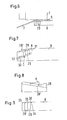
- Fig. 7 shows the pressure shoe 8 on its axial End after a step in a ramp 29 ends.
- the ramp 29 runs parallel to the direction of axis 10 the counter-roller 3.
- a guide 30 arranged, for example in the manner of a hammer head or Dovetail guide.
- An extension member 28 is from an inactive position I can be moved to an active position A.
- the extension element 28 simply becomes the ramp 29 pushed up until the extension element 28 for contact with an end face 31 of the Pressure shoe 8 comes. There the extension element 28 then with means not shown be determined.
- the extension of the foot 32 compensates for the difference in height due to the different axial positions of the extension elements 28, 28 'on the ramp 29.
- extension elements 28, 28 ' are within the Roll shell 7 arranged.
- the relocation takes place with With the help of a drive, not shown, which the Extension elements 28, 28 'mainly in axial Direction.
- the movement in the radial direction then takes place under the action of ramp 29.
- Fig. 8 shows a modified embodiment, at which the ramp 30 'is inclined in a direction that 90 ° to the direction of the ramp of FIG. 7.
- ramp 30 'of FIG. 8 is one Inclined plane that is perpendicular to a press plane, i.e. the connection between the axis 10 of the Counter roll and the axis of rotation of the roll shell 7.
- a press plane i.e. the connection between the axis 10 of the Counter roll and the axis of rotation of the roll shell 7.
- the extension element 28 In the in Fig. 8 position is the extension element 28 inactive.
- Fig. 9 now shows that both the pressure shoe 8 and the extension elements 28, 28 'on their axially outer End have a rounding 33.
- This rounding off 33 is cheap because the jacket is bent at this point and a sharp edge the risk of damage would bring with it.
- the extension elements 28, 28 ' have an axial inside corresponding counter-rounding 34 on that with the rounding 33 coincides, so that one has a plant of Extension elements 28, 28 'on the pressure shoe 8 or on can reach adjacent extension member 28.
Landscapes
- Paper (AREA)
Applications Claiming Priority (2)
| Application Number | Priority Date | Filing Date | Title |
|---|---|---|---|
| DE2002125255 DE10225255B3 (de) | 2002-06-07 | 2002-06-07 | Kalanderanordnung und Verfahren zum Satinieren einer Materialbahn |
| DE10225255 | 2002-06-07 |
Publications (2)
| Publication Number | Publication Date |
|---|---|
| EP1369526A1 true EP1369526A1 (fr) | 2003-12-10 |
| EP1369526B1 EP1369526B1 (fr) | 2006-11-22 |
Family
ID=29432689
Family Applications (1)
| Application Number | Title | Priority Date | Filing Date |
|---|---|---|---|
| EP20030012360 Revoked EP1369526B1 (fr) | 2002-06-07 | 2003-05-30 | Calandre et procédé de calandrage |
Country Status (2)
| Country | Link |
|---|---|
| EP (1) | EP1369526B1 (fr) |
| DE (2) | DE10225255B3 (fr) |
Cited By (5)
| Publication number | Priority date | Publication date | Assignee | Title |
|---|---|---|---|---|
| EP1505203A1 (fr) * | 2003-08-07 | 2005-02-09 | Voith Paper Patent GmbH | Dispositif de traitement d'une bande |
| US6926805B2 (en) * | 2000-01-13 | 2005-08-09 | Metso Paper, Inc. | Method for pressing paper web and a calender or a press device with a movable shoe element |
| EP1596001A1 (fr) * | 2004-05-11 | 2005-11-16 | Voith Paper Patent GmbH | Calandre à pince allongée |
| EP2071075A1 (fr) * | 2007-12-14 | 2009-06-17 | Andritz Küsters GmbH | Dispositif de formation d'une pince élargie |
| AT12473U1 (de) * | 2010-06-22 | 2012-06-15 | Voith Patent Gmbh | Bahnbehandlungsvorrichtung zum glätten einer faserstoffbahn |
Citations (3)
| Publication number | Priority date | Publication date | Assignee | Title |
|---|---|---|---|---|
| DE4322876A1 (de) * | 1993-07-09 | 1993-11-18 | Voith Gmbh J M | Vorrichtung zum Glätten einer Papierbahn oder Kartonbahn |
| DE10001360A1 (de) * | 1999-01-22 | 2000-07-27 | Valmet Karlstad Ab Karlstad | Schuhwalze |
| WO2001051705A1 (fr) | 2000-01-13 | 2001-07-19 | Metso Paper, Inc. | Procede pour presser une bande de papier et calandre ou dispositif de pressage avec sabot mobile |
Family Cites Families (2)
| Publication number | Priority date | Publication date | Assignee | Title |
|---|---|---|---|---|
| SE9804346D0 (sv) * | 1998-12-16 | 1998-12-16 | Valmet Corp | Method and apparatus for calendering paper |
| SE9804347D0 (sv) * | 1998-12-16 | 1998-12-16 | Valmet Corp | Method and apparatus for calendering paper |
-
2002
- 2002-06-07 DE DE2002125255 patent/DE10225255B3/de not_active Expired - Fee Related
-
2003
- 2003-05-30 EP EP20030012360 patent/EP1369526B1/fr not_active Revoked
- 2003-05-30 DE DE50305730T patent/DE50305730D1/de not_active Expired - Lifetime
Patent Citations (3)
| Publication number | Priority date | Publication date | Assignee | Title |
|---|---|---|---|---|
| DE4322876A1 (de) * | 1993-07-09 | 1993-11-18 | Voith Gmbh J M | Vorrichtung zum Glätten einer Papierbahn oder Kartonbahn |
| DE10001360A1 (de) * | 1999-01-22 | 2000-07-27 | Valmet Karlstad Ab Karlstad | Schuhwalze |
| WO2001051705A1 (fr) | 2000-01-13 | 2001-07-19 | Metso Paper, Inc. | Procede pour presser une bande de papier et calandre ou dispositif de pressage avec sabot mobile |
Cited By (6)
| Publication number | Priority date | Publication date | Assignee | Title |
|---|---|---|---|---|
| US6926805B2 (en) * | 2000-01-13 | 2005-08-09 | Metso Paper, Inc. | Method for pressing paper web and a calender or a press device with a movable shoe element |
| EP1505203A1 (fr) * | 2003-08-07 | 2005-02-09 | Voith Paper Patent GmbH | Dispositif de traitement d'une bande |
| EP1596001A1 (fr) * | 2004-05-11 | 2005-11-16 | Voith Paper Patent GmbH | Calandre à pince allongée |
| EP2071075A1 (fr) * | 2007-12-14 | 2009-06-17 | Andritz Küsters GmbH | Dispositif de formation d'une pince élargie |
| EA016852B1 (ru) * | 2007-12-14 | 2012-08-30 | Андритц Кюстерс Гмбх | Устройство формирования расширенной зоны контакта |
| AT12473U1 (de) * | 2010-06-22 | 2012-06-15 | Voith Patent Gmbh | Bahnbehandlungsvorrichtung zum glätten einer faserstoffbahn |
Also Published As
| Publication number | Publication date |
|---|---|
| DE50305730D1 (de) | 2007-01-04 |
| DE10225255B3 (de) | 2004-01-08 |
| EP1369526B1 (fr) | 2006-11-22 |
Similar Documents
| Publication | Publication Date | Title |
|---|---|---|
| EP0370185B1 (fr) | Procédé de lissage d'une rande de papier ou de carton | |
| DE29902451U1 (de) | Vorrichtung zum Kalandrieren von Papier | |
| EP0675224A1 (fr) | Presse pour matériau en bande | |
| DE4411621A1 (de) | Preßmantel | |
| EP0447651B1 (fr) | Rouleau à règlage de flexion | |
| EP1081276A2 (fr) | Système de séchage | |
| DE4415645A1 (de) | Walze für eine Papiermaschine | |
| DE3429695C2 (fr) | ||
| EP0857821A2 (fr) | Dispositif d'aspiration | |
| DE10225255B3 (de) | Kalanderanordnung und Verfahren zum Satinieren einer Materialbahn | |
| DE19544979B4 (de) | Vorrichtung zum Komprimieren, Glätten und/oder Entwässern einer Faserstoffbahn | |
| DE3637108A1 (de) | Pressenwalze, die insbesondere zur behandlung einer papierbahn oder dergleichen dient | |
| CH681863A5 (fr) | ||
| EP2808442B1 (fr) | Dispositif de formation d'une zone de pincement allongée | |
| EP0928843B1 (fr) | Dispositif de pressage | |
| DE2909277A1 (de) | Walze fuer die druckbehandlung von warenbahnen zum glaetten und praegen von papier | |
| DE10204286B4 (de) | Kalander und Verfahren zum Betreiben eines Kalanders | |
| DE60020265T2 (de) | Verfahren und vorrichtung zum pressen einer papierbahn | |
| DE4011365C1 (en) | Control of bending of hollow roll - involves fixed shaft inside roll, with fluid film bearing pads engaging inside surface of roll | |
| DE2836228C2 (de) | Stützelement | |
| DE10225256B4 (de) | Kalanderanordnung und Verfahren zum Behandeln einer Materialbahn | |
| DE10207371B4 (de) | Vorrichtung zum Bilden eines Langspalts | |
| EP1285990B1 (fr) | Dispositif pour formation d'une presse à ligne de contact élargie | |
| DE112007002351T5 (de) | Pressenanordnung in einer Behandlungsvorrichtung einer Papiermaschine / Kartonmaschine oder Finishingmaschine mit einer Metallriemenschleife | |
| DE4042365A1 (de) | Durchbiegungseinstellwalze und deren verwendung |
Legal Events
| Date | Code | Title | Description |
|---|---|---|---|
| PUAI | Public reference made under article 153(3) epc to a published international application that has entered the european phase |
Free format text: ORIGINAL CODE: 0009012 |
|
| AK | Designated contracting states |
Kind code of ref document: A1 Designated state(s): AT BE BG CH CY CZ DE DK EE ES FI FR GB GR HU IE IT LI LU MC NL PT RO SE SI SK TR |
|
| AX | Request for extension of the european patent |
Extension state: AL LT LV MK |
|
| 17P | Request for examination filed |
Effective date: 20031104 |
|
| AKX | Designation fees paid |
Designated state(s): DE FI SE |
|
| GRAP | Despatch of communication of intention to grant a patent |
Free format text: ORIGINAL CODE: EPIDOSNIGR1 |
|
| RAP1 | Party data changed (applicant data changed or rights of an application transferred) |
Owner name: VOITH PATENT GMBH |
|
| GRAS | Grant fee paid |
Free format text: ORIGINAL CODE: EPIDOSNIGR3 |
|
| GRAA | (expected) grant |
Free format text: ORIGINAL CODE: 0009210 |
|
| AK | Designated contracting states |
Kind code of ref document: B1 Designated state(s): DE FI SE |
|
| REF | Corresponds to: |
Ref document number: 50305730 Country of ref document: DE Date of ref document: 20070104 Kind code of ref document: P |
|
| REG | Reference to a national code |
Ref country code: SE Ref legal event code: TRGR |
|
| PLBI | Opposition filed |
Free format text: ORIGINAL CODE: 0009260 |
|
| PLAX | Notice of opposition and request to file observation + time limit sent |
Free format text: ORIGINAL CODE: EPIDOSNOBS2 |
|
| 26 | Opposition filed |
Opponent name: ANDRITZ KUESTERS GMBH & CO. KG Effective date: 20070821 |
|
| PLBB | Reply of patent proprietor to notice(s) of opposition received |
Free format text: ORIGINAL CODE: EPIDOSNOBS3 |
|
| PLAB | Opposition data, opponent's data or that of the opponent's representative modified |
Free format text: ORIGINAL CODE: 0009299OPPO |
|
| R26 | Opposition filed (corrected) |
Opponent name: ANDRITZ KUESTERS GMBH Effective date: 20070821 |
|
| RDAF | Communication despatched that patent is revoked |
Free format text: ORIGINAL CODE: EPIDOSNREV1 |
|
| APBM | Appeal reference recorded |
Free format text: ORIGINAL CODE: EPIDOSNREFNO |
|
| APBP | Date of receipt of notice of appeal recorded |
Free format text: ORIGINAL CODE: EPIDOSNNOA2O |
|
| APAH | Appeal reference modified |
Free format text: ORIGINAL CODE: EPIDOSCREFNO |
|
| APBQ | Date of receipt of statement of grounds of appeal recorded |
Free format text: ORIGINAL CODE: EPIDOSNNOA3O |
|
| PGFP | Annual fee paid to national office [announced via postgrant information from national office to epo] |
Ref country code: SE Payment date: 20100517 Year of fee payment: 8 |
|
| REG | Reference to a national code |
Ref country code: SE Ref legal event code: EUG |
|
| PGFP | Annual fee paid to national office [announced via postgrant information from national office to epo] |
Ref country code: DE Payment date: 20120523 Year of fee payment: 10 |
|
| PLBP | Opposition withdrawn |
Free format text: ORIGINAL CODE: 0009264 |
|
| PGFP | Annual fee paid to national office [announced via postgrant information from national office to epo] |
Ref country code: FI Payment date: 20120511 Year of fee payment: 10 |
|
| REG | Reference to a national code |
Ref country code: DE Ref legal event code: R103 Ref document number: 50305730 Country of ref document: DE Ref country code: DE Ref legal event code: R064 Ref document number: 50305730 Country of ref document: DE |
|
| APBU | Appeal procedure closed |
Free format text: ORIGINAL CODE: EPIDOSNNOA9O |
|
| PG25 | Lapsed in a contracting state [announced via postgrant information from national office to epo] |
Ref country code: SE Free format text: LAPSE BECAUSE OF NON-PAYMENT OF DUE FEES Effective date: 20110531 |
|
| RDAG | Patent revoked |
Free format text: ORIGINAL CODE: 0009271 |
|
| STAA | Information on the status of an ep patent application or granted ep patent |
Free format text: STATUS: PATENT REVOKED |
|
| 27W | Patent revoked |
Effective date: 20130416 |
|
| REG | Reference to a national code |
Ref country code: DE Ref legal event code: R107 Ref document number: 50305730 Country of ref document: DE Effective date: 20130801 |
|
| REG | Reference to a national code |
Ref country code: SE Ref legal event code: ECNC |