BACKGROUND OF THE INVENTION
Field of the Invention
This invention relates to a conveying
apparatus and a conveying system in which a plurality
of feed portions are arranged two-dimensionally in a
distributed manner over a conveying surface, and the
feed portions sequentially feed an article so as to
move the same to a predetermined position on the
conveying surface.
Related Art
Fig. 22 shows a feed portion 1 provided in a
conventional conveying apparatus of the type described.
In this feed portion 1, a rotation shaft 3 is provided
within a twist gear 2 rotatable about a vertical axis,
and a feed roller 4 and an output bevel gear 5 are
fixedly mounted on the rotation shaft3. An input
bevel gear 6 in mesh with a lower side of the output
bevel gear 5 is driven by a servomotor so as to rotate
the feed roller 4, while a spur gear 7 in mesh with the
outer periphery of the twist gear 2 is driven by a
servomotor so as to rotate the twist gear 2 (see Patent
literature 1; JP-A-6-298321). With this construction,
an article is conveyed in an arbitrary direction on a
conveying surface of the conveying apparatus.
In the above conventional conveying
apparatus, however, the roller 4 is provided within the
twist gear 2, and therefore the shapes of the twist
gear 2 and feed roller 4 are limited, so that the
following problems have been encountered. Namely, it
is difficult to form the twist gear 2 into a compact
design since this twist gear receives the feed roller 4
therein, and the interval between the adjacent feed
portions 1 and 1 becomes large. And besides, it is
difficult to form the feed roller 4 into a large size
since this feed roller 4 must be received within the
twist gear 2, and the area of contact of the feed
roller 4 with the article can not be increased, so that
a force can not be efficiently transmitted from the
feed roller 4 to the article. Because of these
factors, it has actually been difficult for the
conventional conveying apparatus to feed the article in
an arbitrary direction on the conveying surface.
SUMMARY OF THE INVENTION
With the above problems in view, it is an
object of this invention to provide a conveying
apparatus and a conveying system in which a force is
efficiently transmitted to an article so as to smoothly
convey the article in an arbitrary direction.
According to the present invention, this
object is achieved by a conveying apparatus as defined
in claim 1 or claim 8 and a conveying system as defined
in claim 33. The dependent claims define preferred and
advantageous embodiments of the invention.
According to the present invention, there is
provided a conveying apparatus wherein a plurality of
feed portions are arranged two-dimensionally in a
distributed manner over a conveying surface for
conveying articles, and the feed portions sequentially
feed each article so as to move it to a predetermined
position on the conveying surface; the apparatus
comprising:
Preferably, an idle shaft is mounted on the
twist base, and is disposed below the feed roller in
parallel relation thereto, and is connected to the feed
roller by gears, and the idle shaft is connected to an
upper end of the vertical shaft by bevel gears.
Preferably, upwardly-open mounting holes are
formed in the fixed base, and each of the feed portions
is formed into a unit which can be removably mounted in
the mounting hole, and when the unit is inserted into
the mounting hole from an upper side, the twist gear is
connected to the twist-purpose servomotor by the gears,
while the vertical shaft is kept connected by the gears
to the feed-purpose servomotor by a weight of the feed
portion.
Preferably, each of the twist gears is
disposed at an upper side of a predetermined wall
provided at the fixed base, while the lower end portion
of each of the vertical shafts is disposed at a lower
side of the wall.
Preferably, the twist gears of the adjacent
feed portions are interconnected by an idle gear, and
the twist-purpose servomotor serves as a common drive
source for a predetermined number of the feed portions.
Preferably, the fixed base has a plurality of
mounting portions provided around each of the feed
portions, and the idle gears, each interconnecting the
adjacent twist gears, are mounted at the mounting
portions, respectively.
Preferably, the lower ends of the vertical
shafts of the adjacent feed portions are interconnected
by an idle gear, and the feed-purpose servomotor serves
as a common drive source for a predetermined number of
the feed portions.
Preferably, the fixed base has a plurality of
mounting portions provided around each of the feed
portions, and the idle gears, each interconnecting the
lower ends of the adjacent vertical shafts, are mounted
at the mounting portions, respectively.
Preferably, the plurality of the feed
portions are arranged linearly, and a common drive
shaft is provided beneath the feed portions, and
extends in a direction of juxtaposition of the feed
portions, and a vertical shaft extends through the
twist base of each feed portion at the axis of rotation
thereof, and a lower end of each of the vertical shafts
is connected to the common drive shaft by bevel gears,
while an upper end thereof is connected to a rotation
shaft of the feed roller by bevel gears, so that the
feed-purpose servomotor serves as a common drive source
for the plurality of feed rollers.
Preferably, a plurality of the feed rollers
of a cylindrical shape are provided at the upper
portion of each of the twist bases in parallel relation
to each other, and the plurality of feed rollers are
interconnected by an idle roller.
Preferably, the plurality of feed portions
are divided into a plurality of groups which are driven
independently of each other.
Preferably, the plurality of feed portions
are arranged in columns and rows in a distributed
manner.
Preferably, the conveying surface has a
square shape, and the plurality of feed portions are
arranged in a distributed manner so that the number of
columns of the feed portions is equal to the number of
rows of the feed portions.
Preferably, there is provided a controller
for the twist-purpose servomotor and the feed-purpose
servomotor, and the controller computes the position of
the article on the basis of information, relating to an
initial position of the article entering the conveying
surface, and feed condition information relating to the
direction and rotating amount of the feed rollers.
Preferably, the controller determines a path
of conveying of the article on the conveying surface on
the basis of the information, relating to the initial
position of the article, and information relating to a
final position indicating a conveying destination of
the article.
Preferably, the controller includes data
storage means for storing layout data representative of
conveying paths of the article on the conveying
surface, and data change means for changing the layout
data stored in the data storage means.
Preferably, the layout data includes entry
position data, representing a position where the
article enters the conveying surface, and exit position
data representing a position where the article exits
the conveying surface.
Preferably, the article can enter and exit
the conveying surface at a plurality of positions, and
the controller determines a conveying path in
accordance with the entry and exit positions of the
article.
Preferably, the controller includes article
recognition means for recognizing the kind of the
article, and conveying designation-determining means
for determining different conveying destinations for
different kinds of articles on the basis of recognition
results of the article recognition means.
Preferably, the controller computes the
position of the article by the use of a vector of a
tangential velocity of the feed roller and the article
relative to each other.
Preferably, a center of an area of contact
between the feed roller and the article is disposed at
the axis of rotation of the twist base.
Preferably, the controller includes signal
transmitting/receiving means for transmitting and
receiving information relative to the controllers of
other conveying apparatuses so that when articles enter
and exit between a conveying apparatus and another
conveying apparatus, information in relation to the
articles is transmitted and received between
controllers of the respective conveying apparatuses.
Preferably, there are provided a plurality of
article detection sensors each of which has a detection
region, disposed in a direction perpendicular to the
conveying surface, and detects the passage of the
article, and the controller recognizes the position
and/or size and/or posture of the article on the basis
of detection results of the article detection sensors.
Preferably, the article detection sensors are
embedded in the conveying surface.
Preferably, the controller causes the article
to move while changing the posture thereof if
necessary.
According to another aspect of the invention,
there is provided a conveying system wherein a
plurality of conveying apparatuses are interconnected
so that the article can be moved between the conveying
apparatuses.
Preferably, in the above conveying system,
there is provided a main controller connected to the
controllers provided respectively at the plurality of
conveying apparatuses, and the main controller controls
the plurality of conveying apparatuses in a coordinated
manner.
BRIEF DESCRIPTION OF THE DRAWINGS
Fig. 1A is a plan view of a portion of one
preferred embodiment of a conveying system of the
present invention.
Fig. 1B is a plan view of a portion of the
conveying system having modified conveying paths.
Fig. 2 is a side-elevational view of a
conveying module constituting the conveying system.
Fig. 3 is a plan view of a conveying module.
Fig. 4 is a perspective view of a portion of
the conveying module, showing its internal structure.
Fig. 5 is a perspective view of a portion of
the conveying module, showing its external structure.
Fig. 6 is a cross-sectional view of a feed
portion.
Fig. 7 is a perspective view of the feed
portion.
Fig. 8 is a cross-sectional view taken along
the line A-A of Fig. 2.
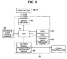
Fig. 9 is a block diagram showing an
electrical construction of a controller.
Fig. 10 is a conceptual view of a vector
control.
Fig. 11A is a plan view of the conveying
module, showing directions of conveying of an article.
Fig. 11B is a plan view of the conveying
module, showing one example of conveying paths.
Fig. 11C is a plan view of the conveying
module, showing a modified conveying path.
Fig. 12 is a conceptual view showing a method
of finding a contour of the article.
Fig. 13 is a conceptual view showing a method
of changing the posture of the article.
Fig. 14 is a plan view showing one example of
conveying systems.
Fig. 15 is a plan view showing another
example of the conveying systems.
Fig. 16 is a plan view showing a further
example of the conveying systems.
Fig. 17 is a cross-sectional view of a feed
portion provided at a second embodiment of a conveying
module of the invention.
Fig. 18 is a cross-sectional view showing a
condition in which the feed portion is removed from a
lower wall of a fixed base.
Fig. 19 is a side-elevational view of the
conveying module.
Fig. 20 is a cross-sectional view showing the
structure of a support portion for an idle gear.
Fig. 21 is a cross-sectional view showing the
structure of a support portion for an idle gear.
Fig. 22 is a cross-sectional view of a
conventional conveying apparatus.
DESCRIPTION OF THE PREFERRED EMBODIMENTS
[First Embodiment]
A first embodiment of the present invention
is now described with reference to Figs. 1 to 16.
As shown in Fig. 1A (which is a plan view), a
conveying system 10, embodying the present invention,
comprises a plurality of conveying modules ("conveying
apparatus" of the present invention) 11 arranged in a
continuous manner, and can convey an article 90, placed
on an upper surface, in a sliding manner. First, the
structure of each conveying module 11 is described.
As shown in Fig. 2, the conveying module 11
includes a table-like fixed base 12. The fixed base 12
includes an upper wall 18 and a lower wall 33
vertically opposed to each other. A plurality of legs
13 extend downwardly from the lower wall 33, and these
legs 13 are fixed, for example, to a floor 91 of a
warehouse or the like. As shown in Fig. 3, the upper
wall 18 has a generally plate-like form of a square
shape, and 36 round holes 19 are formed through this
upper wall 18, and are arranged in 6 columns and 6 rows
(6 × 6 = 36) (Each column extends along two sides of
the square while each row extends along the other two
sides). The lower wall 33 has a generally plate-like
form of a square shape corresponding to that of the
upper wall 18. Feed portions 15 are mounted
respectively on those portions of the lower wall 33
disposed in registry with the plurality of round holes
19, respectively. Upper ends of the feed portions 15
project respectively through the round holes 19
slightly beyond the upper surface of the fixed base 12.
With this construction, the plurality of feed portions
15 are arranged two-dimensionally on a conveying
surface 14 of the conveying module 11.
The term "conveying surface 14" should be
construed as including not only the upper surface of
the fixed base 12 but also the upper ends (more
specifically, upper portions of feed rollers 17
described later) of the feed portions 15 projecting
beyond the upper surface of the fixed base 12, and this
conveying surface 14 serves as a surface for conveying
an article. The fixed base 12 is not limited to the
table-like shape, but can have, for example, a box-like
shape.
As shown in Fig. 4, the feed portion 15
includes the pair of feed rollers 17 and 17 provided at
an upper portion of a twist base 16 rotatable about a
vertical line CL1 perpendicular to the conveying
surface 14 (not shown in Fig. 4). These feed rollers
17 are arranged in a juxtaposed manner in a plane
parallel to the conveying surface 14, and these feed
rollers 17, borne by the twist base 16, are rotated
respectively about horizontal lines CL2 parallel to the
conveying surface 14. As shown in Fig. 5, part of the
two feed rollers 17 and 17 of the feed portion 15
project slightly upwardly from the round hole 19 so as
to contact a lower surface of an article 90.
More specifically, mounting holes 33A are
formed respectively through those portions of the lower
wall 33 at which the feed portions 15 are mounted,
respectively, as shown in Fig. 6, and a bearing tubular
portion 33B extends upright from a peripheral edge of
each mounting hole 33A. A bearing 32 (for example, a
metal bearing) is provided on an inner peripheral
surface and upper surface of the bearing tubular
portion 33B.
The twist base 16 includes a pair of opposed
walls 31 and 31 formed upright on an upper end of a
twist shaft body 30. The twist shaft body 30 is
stepped at its lower end portion into a smaller
diameter, and this smaller-diameter portion of the
twist shaft body 30 is inserted in the bearing tubular
portion 33B, and is slidably borne by an inner
peripheral surface of the bearing 32. A step surface
of the twist shaft body 30, disposed intermediate the
opposite axial ends thereof, is held in sliding contact
with the upper surface of the bearing 32.
A twist gear 34 is fixedly secured to the
lower end surface of the twist shaft body 30. This
twist gear 34 is in the form of a spur gear, and is
received in a lower end portion of the bearing tubular
portion 33B, and is opposed to an inner step surface of
the bearing tubular portion 33B, thereby retaining the
twist base 16 against withdrawal from the bearing
tubular portion 33B.
A through hole 35 is formed vertically
through the twist shaft body 30 of the twist base 16
along a centerline (axis) thereof, and a vertical shaft
36 is rotatably borne by bearings fitted respectively
in opposite end portions of the through hole 35, and an
upper end portion of this vertical shaft 36 projects
into a space formed between the opposed walls 31 and
31.
An idle shaft 38 extends between and are
rotatably borne by lower end portions of the opposed
walls 31 and 31 of the twist base 16. The idle shaft
38 perpendicularly intersects the axis of rotation of
the twist base 16, and this idle shaft 38 is connected
to the upper end of the vertical shaft 36 by a pair of
bevel gears 37A and 37B.
The feed rollers 17 and 17 extend between and
rotatably borne by the upper end portions of the
opposed walls 31 and 31. These feed rollers 17 and 17
are disposed symmetrically with respect to a plane
including the axis of rotation of the idle shaft 38 and
the axis of rotation of the twist base 16. A
constricted portion is formed at one end portion of
each feed roller 17, and a spur gear 39 of a small
diameter is mounted on this constricted portion. The
spur gears 39 of the two feed rollers 17 are connected
to an idle gear 40 fixedly mounted on the idle shaft
38. With this construction, when the vertical shaft 36
is powered to be rotated, the idle shaft 38 rotates
through the connected bevel gears 37A and 37B, and when
the idle shaft 38 thus rotates, the two feed rollers 17
and 17 rotate in the same direction through the
connected spur gears 39 and 40.
In the conveying module 11 of this
embodiment, a plurality of twist bases 16 can be
mechanically interconnected into a group. More
specifically, as shown in Fig. 7, the twist gears 34
and 34, each fixedly secured to the lower surface of
the corresponding twist base 16, are connected together
by idle gears 41, thereby forming the group in which
these twist bases 16 make the same rotational motion in
an interlocked manner. For canceling the grouping, the
idle gears 41 are removed.
Similarly, a plurality of feed portions 15
can be formed into a group by mechanically
interconnecting their feed rollers 17. More
specifically, as shown in Fig. 7, a common drive shaft
42 is provided beneath the feed portions 15, and
extends to perpendicularly intersect the axis of
rotation of each of the twist bases 16, and is
rotatably supported. Bevel gears 43A, fixedly mounted
on the intermediate portion of the common drive shaft
42, are connected respectively to bevel gears 43B
fixedly mounted respectively on lower end portions of
the vertical shafts 36 of the feed portions 15. With
this construction, there is formed the group in which
the feed rollers 17 of the feed portions 15 make the
same rotational motion in an interlocked manner. Also,
when the common drive shafts 42 and 42 of the adjacent
rows are connected together by a timing belt 44 and
pulleys 45 as shown in Fig. 2, the number of the feed
rollers 17 for making the same rotational motion can be
increased. The grouping can be canceled by removing
the bevel gears 43A and 43B or by providing the timing
belts 44 separately.
As shown in Fig. 6, the twist base 16 of the
feed portion 15 is driven by a twist-purpose servomotor
46. The feed rollers 17 are driven by a feed-purpose
servomotor 47. One twist-purpose servomotor 46 is
provided for each group of feed portions 15, and a
drive shaft of the twist-purpose servomotor 46 is
connected to each of the idle gears 41 interconnecting
the twist bases 16 of the same group. With this
construction, the plurality of twist bases 16 of the
same group are driven by one twist-purpose servomotor
46 serving as a common drive source, and therefore the
cost is reduced as compared with the case where such
grouping is not achieved.
One feed-purpose servomotor 47 is provided
for each group of feed portions 15. As shown in Fig.
2, a pulley 48 is fixedly mounted on a drive shaft of
the feed-purpose servomotor 47, and this pulley 48 is
engaged with part of the timing belt 44 interconnecting
the common drive shafts 42 and 42. With this
construction, the plurality of feed rollers 17 of the
same group are driven by one feed-purpose servomotor 47
serving as a common drive source, and therefore the
cost is reduced as compared with the case where such
grouping is not achieved.
Incidentally, one twist-purpose servomotor 46
can be provided for the twist base 16 of each feed
portion 15, and one feed-purpose servomotor 47 can be
provided for the feed rollers 17 of each feed portion
15. With this construction, the degree of freedom with
respect to the direction of conveying of the article 90
increases, and increased variations of conveying paths
can be obtained.
As shown in Fig. 8, a plurality of article
detection sensors 49 are embedded in the upper wall 18
of the fixed base 12. For example, when imaginary
latticed lines are depicted on the conveying surface 14
in such a manner that each feed portion 15 is
surrounded by corresponding portions of these lines,
the article detection sensors 49 are located
respectively at intersections of these lines. Each of
these article detection sensors has a detection region
disposed in a direction perpendicular to the conveying
surface 14, and detects the passage of the article 90
(for example, this sensor is turned on (or activated)
upon passage of the article). Each article detection
sensor 49 can comprise a proximity switch, a laser
sensor or the like.
A controller 50 includes, for example, a CPU
61 as shown in Fig. 9, and this CPU 61 executes a main
program, stored in a ROM 62, at predetermined periods,
and feeds a drive command to a servo amplifier 80 for
the servomotors 46 and 47 to drive the feed portions 15
so as to convey the article 90 along a predetermined
conveying path. Details are described in the
following.
The CPU 61 computes the position of the
article 90 on the basis of the initial position of the
article 90 and a vector of a tangential velocity of the
article 90 and the feed rollers 17 relative to each
other. Here, the vector of the tangential velocity is
also a vector of a travel speed of the article 90, and
starts from the axis of rotation of the twist base 16
of each feed portion 15, and is directed in the
direction of juxtaposition of the two feed rollers 17
and 17, and has a scalar proportional to the rotational
speed of the feed rollers 17. Therefore, the vector of
the tangential velocity is specified by the direction
and rotational speed of the feed rollers 17.
For example, as shown in Fig. 10, a vector
V1, interconnecting the origin P0 (set in a
predetermined position on the conveying surface 14) and
an initial position P1 of the article 90, is found, and
the sum of a vector V2 of a travel speed of the article
90 at the initial position P1 (i.e., a vector of the
tangential velocity of the article relative to the feed
rollers 17) and the vector V1 is found. Therefore, a
vector V3, interconnecting the origin P0 and an arrival
position P2, is found as the sum of the vectors V1 and
V2. Therefore, coordinates of the arrival position P2
of the article 90 (at which the article 90 is located
upon lapse of a unit time after this article is located
at the initial position P1) is calculated. Further, an
arrival position P3 after another unit time is found by
the sum of a vector V4 of the travel speed of the
article 90 at the arrival position P2 and the vector
V3. Then, similarly, the conveying path,
interconnecting passage points of the article 90, is
found. Therefore, in the CPU 61, the conveying path is
beforehand determined by the initial position and final
position of the article 90, and a vector of the travel
speed of the article 90 at each of passage target
points, obtained by dividing this conveying path, is
computed. The servomotors 46 and 47 for the feed
portions 15 are driven on the basis of these vectors.
Therefore, the article 90 can move along the conveying
path.
For example, an EEPROM 63 (corresponding to
"data storage means" of the present invention), storing
layout data relating to conveying paths of the article
90, is provided in the controller 50. The layout data
includes entry position data, representing a position
where the article 90 enters the conveying surface 14,
and exit position data representing a position where
the article 90 exits the conveying surface 14, and a
conveying path is formed by interconnecting the entry
position and exit position of the article 90 by a line
of a predetermined form. Fig. 11A shows one specific
example of conveying path layouts, and in this case, an
upper left portion of the conveying surface 14 is the
entry position of the article 90, and a lower right
portion thereof is the exit position, and these entry
and exit positions are stored respectively as the entry
position data and exit position data of the layout
data.
Fig. 11B shows one example of conveying paths
interconnecting the entry position and the exit
position, and in this case the conveying path extends
obliquely from the entry position at an intermediate
position in a main conveying direction (left-right
direction in Fig. 11B), and then extends in the same
direction as the main conveying direction. Fig. 11C
shows another example of conveying paths, and in this
case the conveying path of the article 90 first extends
in a direction perpendicular to the main conveying
direction, and then extends in the same direction as
the main conveying direction. Here, the conveying path
does not always need to be the one along which the
article 90 is moved continuously toward one side, and
for example the conveying path can be the one along
which the article 90, while repeatedly moved back and
forth on the conveying surface 14, is conveyed to a
predetermined position as when a car is put into a
garage.
The controller 50 includes a console 65
(corresponding to "data change means" of the present
invention) for inputting the layout data. By operating
this console 65, the layout data, stored in the above
data memory, can be renewed.
The CPU 61 of the controller 50 executes, for
example, an article recognition program (corresponding
to "article recognition means" of the present
invention), stored in the ROM 62, at predetermined
periods, and by doing so, the position, size and
posture of the article 90 can be recognized in
accordance with detection results of the article
detection sensors 49. More specifically, among the
plurality of article detection sensors 49, a group of
article detection sensors 49 over which the article 90
is disposed are activated, and the shape of the article
90 can be recognized by these activated article
detection sensors 49. At this time, the group of
activated article detection sensors 49 shift in
accordance with the movement of the article 90.
Therefore, the position, size and posture of the
article 90 can be detected on the basis of the time of
movement of the article 90, the position and activation
time of the activated article detection sensor group.
When the article 90 is one of a simple shape
such as a corrugated cardboard box, a contour line of
the article 90 can be detected by activation of at
least two article detection sensors 49 located
respectively at different positions, as shown in Fig.
12. And, a region, surrounded by four contour lines L1
to L4, can be detected as the shape of the article 90.
Incidentally, the centroid is found from the thus
obtained plane figure of the article 90, and this
centroid can be used as a representative point of the
article 90.
Recognition results of the article
recognition program are inputted into the main program,
and a deviation between the set entry position
(obtained by the layout data) and the actual entry
position is calculated by this main program. If such a
deviation is found, the conveying path of the article
90 and the conveying posture thereof are corrected.
Further, the main program functions to move the article
90 while changing the posture thereof, if necessary.
For changing the posture of the article 90, the
rotational speed of those feed rollers 17, contacting
one of the opposite side edges of the lower surface of
the article 90, is made different from the rotational
speed of those feed rollers 17 (which are spaced from
the first-mentioned feed rollers 17 in a direction
perpendicular to the main conveying direction (left-right
direction in Fig. 13)) contacting the other side
edge of the lower surface of the article 90, as shown
in Fig. 13, and by doing so, that side (upper side in
Fig. 13) of the article, contacting the feed rollers 17
of higher rotational speed, can be turned clockwise
(Fig. 13) so that the article 90 can be directed in the
main conveying direction.
There can be provided a program
(corresponding to "conveying designation-determining
means" of the present invention) which determines
different conveying destinations for different kinds of
articles 90 on the basis of the recognition results of
the article recognition program. More specifically,
when the articles 90 can be judged such that the
articles 90 can be classified into a large size, a
medium size and a small size as shown in Fig. 1B, these
articles can be conveyed to a left end portion, a
central portion and a right end portion with respect to
the main conveying direction according to the size of
the articles.
As shown in Fig. 9, the controller 50
includes an I/O port 66 (corresponding to "signal
transmitting/receiving means" of the present invention)
for transmitting and receiving information relative to
the controllers 50 of other conveying modules 11. A
plurality of controllers 50 for conveying modules 11
can be connected together so that communication can be
effected between their controllers 50, as shown in Fig.
1A. With this construction, for example, when the
article 90 moves forward or backward from one conveying
module 11 to another conveying module 11, information
such as the delivery timing, posture, direction and
size of the article 90, is fed, for example, from the
controller 50 of the upstream conveying module 11 to
the controller 50 of the downstream conveying module
11. As a result, the delivery of the article 90 can be
effected smoothly.
The foregoing is the description of the
construction of the single conveying module 11. The
conveying system 10 comprises a plurality of conveying
modules 11 combined into a predetermined form and the
controllers 50 of these conveying modules 11 connected
together. Figs. 1 and 14 to 16 show examples of
conveying systems 10 in which the conveying modules 11
are freely arranged lengthwise and/or breadthwise into
desired forms, so that these conveying systems 10 have
different width, length and configuration. Here, each
of the conveying modules 11 has a square shape, and the
length and breadth thereof are equal to each other.
Therefore, when the conveying modules 11 are arranged
either lengthwise or breadthwise, the corresponding
sides of the conveying modules 11 are disposed flush
with each other, and the installation can be carried
out easily.
The controllers 50 of all of the conveying
modules 11, forming the conveying system 10, can be
connected to a main controller (not shown in a
drawing), in which case this main controller
collectively controls the operations of all of the
conveying modules 11. In this case, the conveying
system 10 corresponds to "the conveying system" of the
present invention, and also corresponds to "the
conveying apparatus" of the present invention. When
the conveying system 10 is construed as forming "the
conveying apparatus" of the present invention, the main
controller corresponds to "the controller" of the
present invention. Furthermore, the controllers 50 of
the conveying modules 11 are not connected together,
and each conveying module can be controlled by the
individual conveying system 10.
Next, the operation and function of this
embodiment of the above construction are described.
In this embodiment, the conveying module 11
can freely convey the article 90 in all directions,
that is to say, the conveying direction is not limited
to the front, back, left and right directions.
Therefore, a desired number of conveying paths can be
set on the conveying system 10 without providing any
physical obstacle. More specifically, in the conveying
system 10 in which the conveying modules 11 are
arranged linearly as shown in Fig. 14, the articles 90.
can be collected at lateral collecting places at a
desired position in the longitudinal direction of the
conveying system 10 as indicated by arrows in Fig. 14.
Also, the articles 90 can be discharged toward hoppers
81 branching off from the conveying system 10 in
directions inclined relative to the longitudinal
direction thereof. Furthermore, as shown in Fig. 1A,
the direction of the article 90 can be changed by
turning (angularly moving) it, and the distance between
the two articles 90, arranged in the conveying
direction, can be changed by making the rotational
speed of the feed rollers 17, contacting one of the two
articles 90, different from the rotational speed of the
feed rollers 17 contacting the other article 90. By
doing so, the distance between the adjacent articles 90
can be reduced to a minimum, so that the conveying
operation can be carried out efficiently.
As shown in Fig. 15, a plurality of articles
90 can be simultaneously moved respectively along
conveying paths K1, K2 and K3 in parallel relation to
one another, and these conveying paths K1, K2 and K3
can be joined midway, and then this joined path can be
divided.
For example, at a flat site, the conveying
modules can be arranged into a conveying form suited
for conveying articles by a fork lift truck. Namely,
as shown in Fig. 16, the conveying modules 11 are
arranged to form a conveying area of a size
sufficiently large for the articles 90, and a plurality
of branching conveying paths are set on this conveying
area, and by doing so, a plurality of kinds of articles
can be collected at predetermined positions in the
conveying area. And besides, the conveying system is
so constructed that the articles 90 can enter and exit
the conveying area at a plurality of positions as shown
in Fig. 16, and by doing so, the efficiency of
conveying of the articles into and out of the conveying
area can be enhanced. In all of the above cases,
merely by changing the layout data stored in the
controllers 50, the layout of the conveying paths can
be easily effected.
As described above, in the conveying system
10 and the conveying module 11 of this embodiment, by
driving the twist base 16 and the feed rollers 17
respectively by the servomotors 46 and 47, the article
90 can be moved to a desired position, and the degree
of freedom for determining the conveying path
increases. And besides, by operating the console 65,
the layout data of the conveying path can be changed,
and the layout of the conveying path can be easily
changed without the need for moving the facilities.
Furthermore, the article 90 is moved while its posture
is changed if necessary, and therefore the conveying
efficiency is enhanced as compared with the case where
the posture change and the movement are effected
separately.
In the feed portion 15 of the conveying
module 11 of this embodiment, the twist gear 34 of the
twist base 16 is disposed below the feed rollers 17,
and therefore the degree of freedom of the
configurations of the twist gear 34 and feed rollers 17
is higher as compared with the conventional
construction in which the feed roller is provided
within the twist gear. Therefore, a compact design of
the twist gear 34 can be achieved, and the adjacent
feed portions 15 can be disposed closer to each other
as compared with the conventional construction, and
besides a large-size design of the feed rollers 17 can
be achieved, so that the area of contact of each feed
roller 17 with the article can be increased. With this
construction, the force can be efficiently transmitted
from each feed portion 15 to the article 90 so as to
smoothly convey the article 90 in an arbitrary
direction.
The idle shaft 38 is connected to the feed
rollers 17 and the vertical shaft 36 by the gears, and
the bevel gear 37A is mounted on the idle shaft 38.
Therefore, a bevel gear does not need to be mounted on
the rotation shaft of each feed roller 17, and the
degree of freedom of the configuration of the feed
rollers 17 and 17 increases. With this construction,
the pair of feed rollers 17 and 17 can be provided, and
this also increases the area of contact of the feed
rollers 17 with the article. And besides, the
plurality of (two in this embodiment) feed rollers 17
are provided for each feed portion 15, and this also
increases the area of contact between the feed rollers
17 and the article 90.
[Second Embodiment]
This embodiment is shown in Figs. 17 to 21.
Only those portions of this embodiment different in
construction from the first embodiment will be
described below, and those portions identical in
construction to the first embodiment will be designated
by identical reference numerals, respectively, and
repeated description thereof will be omitted.
As shown in Fig. 17, a lower wall 33' of a
fixed base 12, provided at a conveying module 11'
("conveying apparatus" of the present invention), is in
the form of a flat plate, and has a plurality of idle
gear-mounting holes 33F provided around each mounting
hole 33A in which a feed portion 15' is mounted. An
upper surface of the lower wall 33' and inner surfaces
of the mounting holes 33A are covered with a sliding
metal 32M. For example, the idle gear-mounting hole
33F is disposed between any two mounting holes 33A and
33A adjacent to each other in a lengthwise direction,
and also the idle gear-mounting hole 33F is disposed
between any two mounting holes 33A and 33A adjacent to
each other in a breadthwise direction. A gear support
shaft 41S is inserted into the idle gear-mounting hole
33F from the upper side, and is mounted therein, and an
idle gear 41' is rotatably mounted on an upper end
portion of the gear support shaft 41S, while an idle
gear 43D is rotatably mounted on a lower end portion of
the gear support shaft 41S.
A twist base 16', provided at the feed
portion 15' of this embodiment, has a U-shape, and an
end surface of a twist gear 34' is held against and
fixedly secured to a bottom wall of the twist base 16'.
The twist gear 34' has such a construction that a twist
shaft body 34B projects downwardly from a lower end
surface of a spur gear portion 34G. The twist shaft
body 34B is rotatably fitted in the mounting hole 33A.
The lower end surface 34A of the spur gear portion 34G
is slidably held against an upper peripheral edge
portion of the mounting hole 33A by the weight of the
feed portion 15'. With this construction, the feed
portion 15' is held in position on the lower wall 33'.
A spur gear 43C, which is smaller in outer
diameter than the twist shaft body 34B, is fixedly
secured to a lower end portion of a vertical shaft 36
extending vertically through the twist gear 34'. As
appreciated from the comparison between Figs. 17 and
18, the feed portion 15' can be releasably mounted in
the mounting hole 33A in the lower wall 33' from the
upper side without effecting a screw-fastening
operation or the like.
In the conveying module 11' of this
embodiment, merely by inserting the feed portion 15'
into the mounting hole 33A, the spur gear portion 34G
of the twist gear 34' is brought into meshing
engagement with the idle gears 41' on the upper side of
the lower wall 33', and is connected to a twist-purpose
servomotor 46 (see Fig. 19), and at the same time the
spur gear 43C is brought into meshing engagement with
the idle gears 43D on the lower side of the lower wall
33', so that the vertical shaft 36 is kept connected by
the gears to a feed-purpose servomotor 47 (see Fig. 19)
by the weight of the feed portion 15'. With this
construction, the feed portion 15' can be releasably
mounted on the fixed base 12 in easy manner, and the
efficiency of a maintenance operation for the feed
portion 15', as well as the efficiency of an operation
for changing the layout of the feed portions 15', can
be enhanced.
The gear connecting mechanism for connecting
the twist gear 34' to the twist-purpose servomotor 46
and the gear connecting mechanism for connecting the
lower end portion of the vertical shaft 36 to the feed-purpose
servomotor 47 are disposed separately on the
upper and lower sides of the lower wall 33' of the
fixed base 12, respectively, and therefore each of the
gear-connecting mechanisms is simplified in
construction.
And besides, in the fixed base, the plurality
of idle gear-mounting holes 33F are provided around
each of the feed portions 15', so that the degree of
freedom of arrangement of the idle gears 41' and 43D
increases, and therefore the degree of freedom of
combination of the feed portions 15' to be interlocked
to each other increases.
A gear support shaft 41T for supporting only
the idle gear 41' for the twist gear 34' can be mounted
in the idle gear-mounting hole 33F as shown in Fig. 20,
and a gear support shaft 41W for supporting only the
idle gear 43D for the vertical shaft 36 can be mounted
in the idle gear-mounting hole 33F as shown in Fig. 21.
Namely, the idle gear 41' for the twist gear 34' of
each feed portion 15' and the idle gear 43D for the
vertical shaft 36 may be disposed separately.
[Other Embodiments]
The present invention is not limited to the
above constructions, and for example the following
constructions falls within the scope of the present
invention, and further various modifications other than
the following can be made without departing from the
scope of the invention.
In the feed portion provided at the conveying
apparatus of the invention 8, the twist gear of the
twist base is disposed below the feed roller, and
therefore the degree of freedom of the configurations
of the twist gear and feed roller is higher as compared
with the conventional construction in which the feed
roller is provided within the twist gear. Therefore,
the compact design of the twist gear can be achieved,
and the adjacent feed portions can be disposed closer
to each other as compared with the conventional
construction, and besides the large-size design of the
feed roller can be achieved, so that the area of
contact of the feed roller with the article can be
increased. With this construction, the force can be
efficiently transmitted to the article so as to
smoothly convey the article in an arbitrary direction.
In the conveying apparatus of the invention
9, the idle shaft is connected to the feed roller and
the vertical shaft by the gears, and the bevel gear is
mounted on the idle shaft. Therefore, a bevel gear
does not need to be mounted on the feed roller, and the
degree of freedom of the configuration of the feed
roller increases. There can be provided a plurality of
feed rollers connected to the idle shaft by gears, and
by doing so, the area of contact of the feed rollers
with the article can be increased.
In the conveying apparatus of the invention
10, the feed portions is formed into the unit, so that
when this unit is inserted into the mounting hole from
the upper side, the twist gear is connected to the
twist-purpose servomotor by the gears, while the
vertical shaft is kept connected by the gears to the
feed-purpose servomotor by the weight of the feed
portion. Therefore, the feed portion can be easily
mounted on and removed from the fixed base, and the
efficiency of the maintenance operation for the feed
portion, as well as the efficiency of the operation for
changing the layout of the feed portions of the
conveying apparatus, can be enhanced.
In the conveying apparatus of the invention
11, the gear connecting mechanism for connecting the
twist gear to the twist-purpose servomotor and the gear
connecting mechanism for connecting the lower end
portion of the vertical shaft to the feed-purpose
servomotor are disposed separately on the upper and
lower sides of the predetermined wall of the fixed
base, respectively, and therefore each of the gear-connecting
mechanisms is simplified in construction.
In the conveying apparatus of the invention
12, the twist gears of the adjacent feed portions are
interconnected by the idle gear, and therefore the
twist-purpose servomotor serves as a common drive
source for a plurality of twist bases, and the cost can
be reduced.
In the conveying apparatus of the inventions
13 and 15, the fixed base has the plurality of idle
gear mounting portions provided around each of the feed
portions, and therefore the degree of freedom of
arrangement of the idle gears (each interconnecting the
twist gears of the adjacent feed portions) and/or idle
gears (each interconnecting the vertical shafts of the
adjacent feed portions) increases.
In the conveying apparatus of the inventions
14 and 15, the plurality of feed rollers are
interconnected, and therefore the feed-purpose
servomotor serves as a common drive source for a
plurality of feed rollers.
In the conveying apparatus of the invention
17, the plurality of feed rollers of a cylindrical
shape are provided, and therefore the area of contact
of the feed rollers with the article is larger as
compared with the case where one feed roller is
provided, and therefore a larger force can be applied
from the feed rollers to the article.
In the conveying apparatus of the invention
18, the plurality of feed portions are divided into a
plurality of groups which are driven independently of
each other, and therefore a plurality of articles can
be simultaneously conveyed from different positions on
the conveying surface in different directions, so that
the conveying efficiency is enhanced.
In the conveying apparatus of the invention
19, the plurality of feed portions are arranged in
columns and rows in a distributed manner, and therefore
the positions of the feed portions can be easily stored
as data in each controller.
In the conveying apparatus of the invention
20, the conveying surface has a square shape, and the
plurality of feed portions are so arranged in a
distributed manner in that the number of columns of the
feed portions is equal to the number of rows of the
feed portions. Therefore, it is not necessary to
distinguish between the length and breadth, and the
degree of freedom of arrangement of the conveying
apparatus increases.
In the conveying apparatus of the invention
21, the controller can compute the position of the
article on the basis of information, relating to the
initial position of the article entering the conveying
surface, and the feed condition information relating to
the direction and rotating amount of the feed roller,
thereby controlling the position of the article.
In the conveying apparatus of the invention
22, the controller can determine the path of conveying
of the article on the conveying surface on the basis of
the information, relating to the initial position of
the article, and information relating to the final
position indicating a conveying destination of the
article.
In the conveying apparatus of the invention
23, the layout data, stored in the data storage means,
can be changed by operating the data change means, and
by doing so, the layout can be changed without the need
for the movement of the facilities as required in the
conventional construction.
In the conveying apparatus of the invention
24, the layout data includes the article entry position
data and the article exit position data, and therefore
the conveying apparatus can accurately send the article
to other conveying apparatus, disposed adjacent to the
conveying surface thereof, or can accurately receive
the article from the other conveying apparatus.
In the conveying apparatus of the invention
25, the article can enter and exit the conveying
surface at a plurality of positions, and therefore the
articles can be conveyed in a parallel, juxtaposed
manner, so that the conveying efficiency is enhanced.
In the conveying apparatus of the invention
26, the articles can be assorted into different
conveying designations in accordance with the kind of
the articles, and can be collected at such different
places.
In the construction of the invention 27, the
position of the article can be computed by the use of a
vector of the tangential velocity of the feed roller
and the article relative to each other. In this case,
the center of the area of contact between the feed
roller and the article is disposed at the axis of
rotation of the twist base (the invention 28), and by
doing so, the starting point of the vector of the
tangential velocity can be set on the axis of rotation
of the twist base. Therefore, even when the direction
of the vector is varied, the starting point of the
vector does not change, so that the calculation of the
vector can be easily effected.
In the conveying apparatus of the invention
29, when the movement (entry and exist) of the article
is carried out between the conveying apparatus and
other conveying apparatus, the information is
transmitted between the controllers of these conveying
apparatuses, and therefore the movement of the article
between the two conveying apparatuses can be carried
out smoothly.
In the conveying apparatus of the invention
30, the article can be conveyed in accordance with the
position, size and posture of the article recognized by
the article detection sensors. When the article
detection sensors are embedded in the conveying surface
(the invention 31), the overall construction of the
conveying apparatus, having the article detection
sensors, is made compact.
In the conveying apparatus of the invention
32, the article is moved while being changed in posture
if necessary, and therefore the conveying efficiency is
enhanced as compared with the case where the posture
change and the movement are effected separately.
A plurality of conveying apparatuses
described above can be interconnected so that the
article can be moved between the conveying apparatuses
(the invention 33). In this case, there can be
provided a main controller connected to the controllers
provided respectively at the plurality of conveying
apparatuses, and the main controller controls the
plurality of conveying apparatuses in a coordinated
manner.