EP1378331B1 - Anschlagmaschine - Google Patents
Anschlagmaschine Download PDFInfo
- Publication number
- EP1378331B1 EP1378331B1 EP03009292A EP03009292A EP1378331B1 EP 1378331 B1 EP1378331 B1 EP 1378331B1 EP 03009292 A EP03009292 A EP 03009292A EP 03009292 A EP03009292 A EP 03009292A EP 1378331 B1 EP1378331 B1 EP 1378331B1
- Authority
- EP
- European Patent Office
- Prior art keywords
- profiles
- anvil
- fixing machine
- stopper
- machine
- Prior art date
- Legal status (The legal status is an assumption and is not a legal conclusion. Google has not performed a legal analysis and makes no representation as to the accuracy of the status listed.)
- Expired - Lifetime
Links
- 229910052782 aluminium Inorganic materials 0.000 claims description 6
- XAGFODPZIPBFFR-UHFFFAOYSA-N aluminium Chemical compound [Al] XAGFODPZIPBFFR-UHFFFAOYSA-N 0.000 claims description 6
- 239000004411 aluminium Substances 0.000 claims 1
- 239000000463 material Substances 0.000 description 10
- 238000011161 development Methods 0.000 description 3
- 230000018109 developmental process Effects 0.000 description 3
- 230000005540 biological transmission Effects 0.000 description 2
- 238000013461 design Methods 0.000 description 2
- 238000003780 insertion Methods 0.000 description 2
- 230000037431 insertion Effects 0.000 description 2
- 238000003754 machining Methods 0.000 description 2
- 229910052751 metal Inorganic materials 0.000 description 2
- 239000002184 metal Substances 0.000 description 2
- 238000000034 method Methods 0.000 description 2
- 238000012545 processing Methods 0.000 description 2
- 230000006978 adaptation Effects 0.000 description 1
- 230000015572 biosynthetic process Effects 0.000 description 1
- 239000011111 cardboard Substances 0.000 description 1
- 238000006243 chemical reaction Methods 0.000 description 1
- JEIPFZHSYJVQDO-UHFFFAOYSA-N iron(III) oxide Inorganic materials O=[Fe]O[Fe]=O JEIPFZHSYJVQDO-UHFFFAOYSA-N 0.000 description 1
- 239000010985 leather Substances 0.000 description 1
- 238000004519 manufacturing process Methods 0.000 description 1
- 229910001092 metal group alloy Inorganic materials 0.000 description 1
- 150000002739 metals Chemical class 0.000 description 1
- 239000004033 plastic Substances 0.000 description 1
- 239000002023 wood Substances 0.000 description 1
Images


Classifications
-
- B—PERFORMING OPERATIONS; TRANSPORTING
- B27—WORKING OR PRESERVING WOOD OR SIMILAR MATERIAL; NAILING OR STAPLING MACHINES IN GENERAL
- B27F—DOVETAILED WORK; TENONS; SLOTTING MACHINES FOR WOOD OR SIMILAR MATERIAL; NAILING OR STAPLING MACHINES
- B27F7/00—Nailing or stapling; Nailed or stapled work
- B27F7/15—Machines for driving in nail- plates and spiked fittings
Definitions
- the invention relates to a stopper for attachable to box-shaped container fittings with a frame that is designed to be divided and consists of profiles and a receiving plate, a drive, an anvil and a tool holder.
- stop machines of the type mentioned are used.
- the material to be handled for example the upper and the lower part of a box-shaped container, is placed on the anvil, which is to be provided with the fitting, which Part of the machine, and the stopper machine is actuated, whereby the fitting containing stopper tool is hammer-like moved to the anvil and all impact tips of the fitting are introduced simultaneously into the sling.
- the stopper tool is moved away from the anvil again, so either the same material to be handled at another location provided with another fitting or new material can be placed on the anvil.
- lifting machines of this type are individual machines, which are either supplied by hand or automatically to the respective fitting and beaten against the material to be handled (cf., DE-OS 1 602 568).
- these individual machines either hinges or locks are struck, the hinges are usually struck from above, the closures usually from below.
- the same stopper machine in an adjustable distance from each other arranged stop tools for simultaneously abutting multiple fittings have been used (see DE-PS 403 709); or two stop machines, each with a stopper tool, have been coupled relative to one another to a twin machine so as to be movable relative to one another (cf DE-OS 2 808 881).
- To further rationalize the machining process and to increase the degree of automation stop machines are known, which are combined to form a machining center in which a gripper system automatically guides the material to be handled through the machining center and fitted with fittings (see DE 43 02 766 A1).
- the high degree of automation of the stop machines on the market also entails high initial costs and a high cost in the conversion to new series, which is not economical to accomplish for very small series. Also, the space requirement of the automated or coupled stop machines is high.
- a stopper machine of the type mentioned is known.
- the receiving plate is pivotable about the profiles by a hinge. This is to solve the problem of simplifying slipping around the anvil or removing a box-shaped container.
- the object of the invention to provide a pivotable stopper can be struck in the fittings from above or from below.
- This object is achieved in that the receiving plate is pivotable about the profiles by a hinge, wherein the receiving plate is provided with a fixing unit and in the swung-around state, the fixing unit receives a bracket which is provided with an anvil.
- a stopper for attachable to box-shaped container fittings is created, which is specially adapted to the needs of very small series.
- the impact machine has a low degree of automation. As a result, the space requirement and the
- the frame is made of aluminum.
- the weight of the device is additionally reduced.
- the risk of rust attack is reduced.
- a height adjustment is provided on the machine.
- an adjustment of the device to the material thickness of the material to be stopped is possible in a simple manner.
- the stroke machine chosen as the embodiment has a base plate 1, with which it rests on the ground.
- the base plate 1 is made of aluminum.
- an anvil holder 2 is provided on the base body 1, on the base body 1, an anvil holder 2 is provided.
- the anvil holder 2 is preferably made of light metal.
- the anvil holder 2 tapers in the front view wedge-like starting from its the base plate 1 facing foot part to its base plate 1 facing away from the headboard. At the head part of the anvil holder 2 an anvil 3 is attached.
- the support tables 4 are fixed in height adjustable by guides 5 on the anvil holder 2.
- the support tables 4 are aligned at an angle to the horizontal, so that the upper and lower part of a box-shaped container are each aligned at an angle to each other during the attack process.
- 4 adjustable side guides can be provided on the support tables, which serve as a holding device for the upper and lower part of the box-shaped container.
- the side guides can be adjustable in particular in the direction of movement of the container.
- they can be resiliently mounted.
- the stopper machine has a frame, which consists in the embodiment of aluminum profiles 6 and 9 and a receiving plate 7.
- the profiles 6 form the floor facing part of the frame, the profiles 9 facing away from the ground part of the frame.
- the profiles 6 of the frame are rectangular provided on the front sides of the base plate 1.
- the receiving plate 7 is arranged on the profiles 6, which can also be referred to as a top plate.
- the receiving plate 7 is made of aluminum. It divides the frame into an upper part with the profiles 9 and a lower part with the profiles 6.
- the receiving plate 7 is pivotally mounted on the profiles. It has for this purpose a hinge 8, which is arranged in the embodiment on one of the two end sides of the receiving plate 7 and on a longitudinal side of one of the two profiles 6. Due to the selected arrangement and design of the hinge 8 results for the receiving plate 7, a pivoting range of 180 °.
- the receiving plate 7 is provided with a fixing unit 18.
- the profiles 9 are mounted on the receiving plate 7 at right angles to this aligned.
- the profiles 9 are also formed in the embodiment in the form of aluminum profiles.
- a frame 10 is mounted on the receiving plate 7, which holds a - usually pneumatic - drive 11 and a transmission part 12.
- a tool holder 13 or a tool in the manner of a plunger is moved up and down substantially perpendicular to the receiving plate 7.
- the tool holder 13 is designed such that it can accommodate both hinge and closure tools.
- a height adjustment 14 is provided which allows adaptation to the material thickness of the fittings to be fitted.
- a support or cover plate 16 is arranged on the receiving plate 7 opposite ends of the profiles 9 .
- the attachment of the plate 16 is effected by means of quick fasteners 17th
- the profiles 9 in this case with their ends facing away from the receiving plate 7 on the ground. They then act as supports.
- the length of the profiles 9 is advantageously chosen that such a placement on the ground is possible to ensure a stable state.
- pivoting the stopper is converted in a few steps from a hinge to a closing machine.
- the support and cover plate 16 is fastened to the ends of the profiles 6 facing away from the floor by means of the quick-release fasteners 17.
- the fastening unit 18 receives in this case shown in Figure 2, a bracket 19, which is provided with an anvil 20.
- a closure stopper 21 is then provided.
- the hinges are slid over an insertion rail (not shown) attached to the hinge tool front, with one hinge advancing the next.
- the hinges are guided by means of a suit magnet to the An horrst Zi.
- the hinge length is specified by the tool.
- the insertion rail and the pressure pad are held by dowel pins. This creates the opportunity to make the tool itself made of hardened material.
- the formation of the stop of the machine according to the invention makes it possible to be used both as a hinge stop and as a stopper.
- the stopper machine according to the invention has a compact design. In the state shown in Figures 1, 3 and 4, it has a footprint of about 0.5 m in width and about 0.2 m in depth; in the swung-open state ( Figure 2), the width is about 1 m. The height of the impact machine is less than 1.5 m. The stop area is approx. 0.5 m. It is suitable as a table machine.
- the weight of the impact device according to the invention is low; in the exemplary embodiment, it is less than 40 kg. This, in conjunction with the small dimensions of the stopper machine created the ability to ship the machine in the preassembled state by mail or parcel service, which is a considerable simplification in the field of shipping.
Landscapes
- Engineering & Computer Science (AREA)
- Mechanical Engineering (AREA)
- Life Sciences & Earth Sciences (AREA)
- Forests & Forestry (AREA)
- Bending Of Plates, Rods, And Pipes (AREA)
- Portable Nailing Machines And Staplers (AREA)
- Presses And Accessory Devices Thereof (AREA)
- Perforating, Stamping-Out Or Severing By Means Other Than Cutting (AREA)
- Sealing Of Jars (AREA)
- Valve Device For Special Equipments (AREA)
Description
- Die Erfindung betrifft eine Anschlagmaschine für an kastenförmige Behälter anschlagbare Beschläge mit einem Rahmen, der geteilt ausgebildet ist und aus Profilen sowie einer Aufnahmeplatte besteht, einem Antrieb, einem Amboss und einer Werkzeugaufnahme.
- Um kastenförmige Behälter, wie Kisten, Kästen, Koffer oder Etuis aus Holz, Pappe, Leder, Kunststoff oder dergleichen mit einem oder mehreren Beschlägen, wie Scharnieren, Verschlüssen, Handgriffen oder dergleichen zu beschlagen, werden Anschlagmaschinen der eingangs genannten Art verwendet. Das Anschlaggut, zum Beispiel das Ober- und das Unterteil eines kastenförmigen Behälters, wird mit der Stelle, die mit einem Beschlag versehen werden soll, auf den Amboss gelegt, der Bestandteil der Maschine ist, und die Anschlagmaschine betätigt, wodurch das den Beschlag enthaltende Anschlagwerkzeug hammerartig auf den Amboss zu bewegt wird und alle Einschlagspitzen des Beschlags gleichzeitig in das Anschlaggut eingebracht werden. Innerhalb des Anschlagtakts wird dann das Anschlagwerkzeug wieder von dem Amboss wegbewegt, sodass entweder dasselbe Anschlaggut an einer anderen Stelle mit einem weiteren Beschlag versehen oder aber neues Anschlaggut auf den Amboss gelegt werden kann.
- Anschlagmaschinen dieser Art sind in der Regel Einzelmaschinen, denen entweder von Hand oder automatisch der jeweilige Beschlag zugeführt und an das Anschlaggut geschlagen wird (vgl. DE-OS 1 602 568). Bei diesen Einzelmaschinen werden entweder Scharniere oder Verschlüsse angeschlagen, wobei die Scharniere in der Regel von oben, die Verschlüsse in der Regel von unten angeschlagen werden. Um die Zeit, die für das Anschlagen von Beschlägen an kastenförmige Behälter vergeht, zu verringern und den Anschlagvorgang zu rationalisieren, sind auch schon in derselben Anschlagmaschine mehrere in einstellbarem Abstand voneinander angeordnete Anschlagwerkzeuge zum gleichzeitigen Anschlagen mehrerer Beschläge verwendet worden (vgl. DE-PS 2 403 709); oder es sind zwei Anschlagmaschinen mit je einem Anschlagwerkzeug relativ zueinander beweglich zu einer Zwillingsmaschine gekuppelt worden (vgl. DE-OS 2 808 881). Zur weiteren Rationalisierung des Bearbeitungsvorgangs sowie zur Erhöhung des Automatisierungsgrades sind Anschlagmaschinen bekannt, die zu einem Bearbeitungszentrum zusammengefasst sind, in dem ein Greifersystem das Anschlaggut automatisch durch das Bearbeitungszentrum führt und mit Beschlägen versieht (vgl. DE 43 02 766 A1).
- Die vorgenannte Entwicklung im Bereich der Anschlagmaschinen dient im Wesentlichen der Erhöhung der Produktionsleistung bei mindestens gleicher Qualität. Insbesondere die zuletzt genannten Bearbeitungszentren sind jedoch allein für sehr große Stückzahlen geeignet, da der Investionsaufwand sowie die Betriebskosten der genannten Bearbeitungszentren für kleine Stückzahlen nicht rentabel ist. Häufig besteht jedoch in der Praxis ein Bedarf für äußerst kleine Serien, für die die zur Zeit auf dem Markt befindlichen Vorrichtungen nicht rentabel betrieben werden können.
- Der hohe Automatisierungsgrad der auf dem Markt befindlichen Anschlagmaschinen zieht zudem hohe Anschaffungskosten sowie einen hohen Aufwand bei der Umrüstung auf neue Serien nach sich, der bei Kleinstserien nicht ökonomische zu bewerkstelligen ist. Auch ist der Platzbedarf der automatisierten bzw. gekuppelten Anschlagmaschinen hoch.
- Aus der DE 11 17 370 B ist eine Anschlagmaschine der eingangs genannten Art bekannt. Bei der bekannten Anschlagmaschine ist die Aufnahmeplatte durch ein Scharnier um die Profile schwenkbar. Damit soll das Problem gelöst werden, das Überstülpen um den Amboss oder das Abnehmen eines kastenförmigen Behälters zu vereinfachen.
- Dem gegenüber liegt der Erfindung die Aufgabe zu Grunde, eine schwenkbare Anschlagmaschine zu schaffen, bei der Beschläge von oben bzw. von unten angeschlagen werden können. Diese Aufgabe wird erfindungsgemäß dadurch gelöst, dass die Aufnahmeplatte durch ein Scharnier um die Profile schwenkbar ist, wobei die Aufnahmeplatte mit einer Befestigungseinheit versehen ist und im umgeschwenkten Zustand die Befestigungseinheit einen Bügel aufnimmt, der mit einem Amboss versehen ist.
- Mit der Erfindung ist eine Anschlagmaschine für an kastenförmige Behälter anschlagbare Beschläge geschaffen, die speziell an die Bedürfnisse von Kleinstserien angepasst ist. Insbesondere weist die Anschlagmaschine einen geringen Automatisierungsgrad auf. Dadurch bedingt ist der Platzbedarf sowie das
- Gewicht der Maschine außerordentlich gering. Durch die Schwenkbarkeit der Anschlagmaschine besteht zudem die Möglichkeit, Scharniere in gewohnter Art von oben anzuschlagen; Verschlüsse nach dem Schwenken der Vorrichtung von unten anzuschlagen.
- In Weiterbildung der Erfindung ist der Rahmen aus Aluminium hergestellt. Hierdurch ist das Gewicht der Vorrichtung zusätzlich reduziert. Gleichzeitig ist die Gefahr von Rostbefall gemindert.
- Vorteilhaft ist an der Maschine eine Höhenverstellung vorgesehen. Hierdurch ist auf einfach Weise ein Anpassen der Vorrichtung an die Materialstärke des Anschlaggutes möglich.
- Andere Weiterbildungen und Ausgestaltungen der Erfindung sind in den übrigen Unteransprüchen angegeben. Ein Ausführungsbeispiel der Erfindung ist in der Zeichnung dargestellt und wird nachfolgend im Einzelnen beschrieben. Es zeigen:
- Figur 1
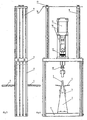
- eine perspektivische Darstellung einer Anschlagmaschine;
- Figur 2
- eine perspektivische Darstellung der in Figur 1 dargestellten Anschlagmaschine in umgeschwenktem Zustand;
- Figur 3
- die Seitenansicht von rechts der in Figur 1 dargestellten Anschlagmaschine und
- Figur 4
- die Vorderansicht der in Figur 1 dargestellten Anschlagmaschine.
- Die als Ausführungsbeispiel gewählte Anschlagmaschine weist eine Grundplatte 1 auf, mit der sie auf dem Boden aufsteht. Die Grundplatte 1 ist aus Aluminium hergestellt. Auf dem Grundkörper 1 ist ein Ambosshalter 2 vorgesehen. Der Ambosshalter 2 ist vorzugsweise aus Leichtmetall angefertigt. Der Ambosshalter 2 verjüngt sich in der Stirnansicht keilartig ausgehend von seinem der Grundplatte 1 zugewandten Fußteil zu seinem der Grundplatte 1 abgewandten Kopfteil. An dem Kopfteil des Ambosshalters 2 ist ein Amboss 3 befestigt.
- Seitlich sind an dem Ambosshalter 2 Auflagetische 4 für das Anschlaggut, in der Regel kastenförmige Behälter, vorgesehen. Die Auflagetische 4 sind über Führungen 5 an dem Ambosshalter 2 höhenverstellbar befestigt. Wie insbesondere der Vorderansicht gemäss Figur 4 zu entnehmen ist, sind die Auflagetische 4 unter einem Winkel zur Horizontalen ausgerichtet, sodass Ober- und Unterteil eines kastenförmigen Behälters jeweils unter einem Winkel beim Anschlagvorgang zueinander ausgerichtet sind. Damit der Behälter beim Anschlagen nicht auseinanderklafft, können an den Auflagetischen 4 verstellbare Seitenführungen vorgesehen sein, die als Haltevorrichtung für Ober- und Unterteil des kastenförmigen Behälters dienen. Die Seitenführungen können insbesondere in Bewegungsrichtung der Behälter verstellbar sein. Vorteilhaft können sie federnd gelagert sein.
- Die Anschlagmaschine weist einen Rahmen auf, der im Ausführungsbeispiel aus Aluminiumprofilen 6 und 9 sowie einer Aufnahmeplatte 7 besteht. Die Profile 6 bilden den dem Boden zugewandten Teil des Rahmens, die Profile 9 den dem Boden abgewandten Teil des Rahmens. Die Profile 6 des Rahmens sind rechtwinklig an den Stirnseiten der Grundplatte 1 vorgesehen. An ihrem freien Ende ist auf den Profilen 6 die Aufnahmeplatte 7 angeordnet, die auch als Kopfplatte bezeichnet werden kann. Die Aufnahmeplatte 7 ist aus Aluminium hergestellt. Sie teilt den Rahmen in einen oberen Teil mit den Profilen 9 und einem unteren Teil mit den Profilen 6. Die Aufnahmeplatte 7 ist schwenkbar an den Profilen angeordnet. Sie weist hierzu ein Scharnier 8 auf, das im Ausführungsbeispiel an einer der beiden Stirnseiten der Aufnahmeplatte 7 sowie an einer Längsseite eines der beiden Profile 6 angeordnet ist. Durch die gewählte Anordnung und Ausbildung des Scharniers 8 ergibt sich für die Aufnahmeplatte 7 ein Schwenkbereich von 180°. Die Aufnahmeplatte 7 ist mit einer Befestigungseinheit 18 versehen.
- Auf der den Profilen 6 abgewandten Seite sind auf der Aufnahmeplatte 7 rechtwinklig zu dieser ausgerichtet die Profile 9 befestigt. Die Profile 9 sind im Ausführungsbeispiel ebenfalls in Form von Aluminium-Profilen ausgebildet. Zwischen den Profilen 9 ist auf der Aufnahmeplatte 7 ein Gestell 10 befestigt, das einen - in der Regel pneumatischen - Antrieb 11 sowie einen Getriebeteil 12 hält. Mit Hilfe des Antriebs 11 sowie des Getriebeteils 12 wird eine Werkzeugaufnahme 13 bzw. ein Werkzeug nach Art eines Stößels im Wesentlichen senkrecht zu der Aufnahmeplatte 7 auf- und abbewegt. Die Werkzeugaufnahme 13 ist derart ausgebildet, dass sie sowohl Scharnier- als auch Verschlusswerkzeuge aufnehmen kann. Zwischen Getriebeteil 12 und Werkzeugaufnahme 13 ist eine Höhenverstellung 14 vorgesehen, die eine Anpassung an die Materialstärke der anzuschlagenden Beschläge ermöglicht. Zur Führung des Stößels dient die in der Kopf- bzw. Aufnahmeplatte 7 vorgesehene Öffnung 15, die dessen Durchtritt in Richtung des Ambosses 3 ermöglicht. Auf den der Aufnahmeplatte 7 abgewandten Enden der Profile 9 ist eine Auflage- bzw. Abdeckplatte 16 angeordnet. Die Befestigung der Platte 16 erfolgt mit Hilfe von Schnellverschlüssen 17.
- Wie dem Ausführungsbeispiel in Figur 2, in dem die Anschlagmaschine in umgeschwenktem Zustand dargestellt ist, zu entnehmen ist, stehen die Profile 9 in diesem Fall mit ihren der Aufnahmeplatte 7 abgewandten Enden auf dem Boden auf. Sie fungieren dann als Stützen. Die Länge der Profile 9 ist vorteilhaft so gewählt, dass eine solche Aufstellung auf dem Boden möglich ist, um einen stabilen Stand zu gewährleisten. Durch das Umschwenken ist die Anschlagmaschine mit wenigen Handgriffen von einer Scharnier- auf eine Verschlussmaschine umgerüstet. Die Auflage- und Abdeckplatte 16 wird hierzu auf den dem Boden abgewandten Enden der Profile 6 mit Hilfe der Schnellverschlüsse 17 befestigt. Für die Bearbeitung ist hierdurch eine Ablage geschaffen. Die Befestigungseinheit 18 nimmt in diesem in Figur 2 dargestellten Fall einen Bügel 19 auf, der mit einem Amboss 20 versehen ist. In der Werkzeugaufnahme 13 ist dann ein Verschlussanschlagwerkzeug 21 vorgesehen.
- Bei der Bearbeitung werden die Scharniere über eine - nicht dargestellte - Einführschiene, die an der Scharnierwerkzeug-Vorderseite befestigt ist, eingeschoben, wobei ein Scharnier das nächste vorantreibt. Die Scharniere werden mittels eines Anzugsmagneten an den Andruckstempel herangeführt. Die Scharnierlänge ist vom Werkzeug vorgegeben. Die Einführschiene und der Andruckstempel sind durch Passstifte gehalten. Hierdurch ist die Möglichkeit geschaffen, das Werkzeug selbst aus gehärtetem Material anzufertigen. Die Ausbildung des Anschlags der erfindungsgemäßen Maschine ermöglicht es, sowohl als Scharnieranschlag als auch als Verschlussanschlag verwendet zu werden.
- Die erfindungsgemäße Anschlagmaschine weist eine kompakte Bauweise auf. In dem in den Figuren 1, 3 und 4 dargestellten Zustand hat sie einen Platzbedarf von ca. 0,5 m in der Breite und ca. 0,2 m in der Tiefe; in aufgeschwenktem Zustand (Figur 2) beträgt die Breite ca. 1 m. Die Höhe der Anschlagmaschine ist kleiner als 1,5 m. Der Anschlagbereich liegt bei ca. 0,5 m. Sie eignet sich unter anderem als Tischmaschine.
- Durch die Verwendung von Leichtmetallen bzw. Leichmetalllegierungen ist das Gewicht der erfindungsgemäßen Anschlagmaschine gering; im Ausführungsbeispiel beträgt es weniger als 40 kg. Hierdurch ist in Verbindung mit den geringen Abmessungen der Anschlagmaschine die Möglichkeit geschaffen, die Maschine in vormontiertem Zustand per Post oder Paketdienst zu verschicken, was eine erhebliche Vereinfachung im Bereich des Versands darstellt.
Claims (6)
- Anschlagmaschine für an kastenförmige Behälter anschlagbare Beschläge mit einem Rahmen, der geteilt ausgebildet ist und aus Profilen (6, 9) sowie einer Aufnahmeplatte (7) besteht, einem Antrieb (11), einem Amboss (3) und einer Werkzeugaufnahme (13), dadurch gekennzeichnet, dass die Aufnahmeplatte (7) durch ein Scharnier (8) um die Profile (6) schwenkbar ist, wobei die Aufnahmeplatte im umgeschwenkten Zustand mit einer Befestigungseinheit (18) einen Bügel (19) aufnimmt, den mit einem Amboss (20) versehen ist.
- Anschlagmaschine nach Anspruch 1, dadurch gekennzeichnet, dass auf der Aufnahmeplatte (7) ein Gestell (10) befestigt ist, das den Antrieb (11) hält.
- Anschlagmaschine nach Anspruch 1 oder 2, dadurch gekennzeichnet, dass in der Aufnahmeplatte (7) eine Öffnung (15) vorgesehen ist.
- Anschlagmaschine nach einem der Ansprüche 1 bis 3, dadurch gekennzeichnet, dass die Werkzeugaufnahme (13) zur Aufnahme von Scharnier- und Verschlusswerkzeugen geeignet ist.
- Anschlagmaschine nach einem der Ansprüche 1 bis 4, dadurch gekennzeichnet, dass der Rahmen aus Aluminium hergestellt ist.
- Anschlagmaschine nach einem der Ansprüche 1 bis 5, dadurch gekennzeichnet, dass eine Höhenverstellung (14) vorgesehen ist.
Applications Claiming Priority (2)
| Application Number | Priority Date | Filing Date | Title |
|---|---|---|---|
| DE20210195U DE20210195U1 (de) | 2002-07-02 | 2002-07-02 | Anschlagmaschine |
| DE20210195U | 2002-07-02 |
Publications (2)
| Publication Number | Publication Date |
|---|---|
| EP1378331A1 EP1378331A1 (de) | 2004-01-07 |
| EP1378331B1 true EP1378331B1 (de) | 2007-03-28 |
Family
ID=7972741
Family Applications (1)
| Application Number | Title | Priority Date | Filing Date |
|---|---|---|---|
| EP03009292A Expired - Lifetime EP1378331B1 (de) | 2002-07-02 | 2003-04-24 | Anschlagmaschine |
Country Status (3)
| Country | Link |
|---|---|
| EP (1) | EP1378331B1 (de) |
| AT (1) | ATE358002T1 (de) |
| DE (2) | DE20210195U1 (de) |
Families Citing this family (1)
| Publication number | Priority date | Publication date | Assignee | Title |
|---|---|---|---|---|
| CN114274284B (zh) * | 2021-12-31 | 2022-07-22 | 广东展丰智能设备有限公司 | 一种钉枪用枪架组件 |
Family Cites Families (4)
| Publication number | Priority date | Publication date | Assignee | Title |
|---|---|---|---|---|
| DE1009910B (de) * | 1953-11-04 | 1957-06-06 | Heinrich Mezger | Heftmaschine mit mehreren Heftaggregaten |
| DE1117370B (de) * | 1960-07-07 | 1961-11-16 | Heinrich Mezger | Heftmaschine zur Herstellung von Boeden an Faltkartons |
| DE2403709C2 (de) * | 1974-01-26 | 1983-01-05 | Schmale GmbH & Co KG, 5880 Lüdenscheid | Anschlagmaschine |
| DE2555782A1 (de) * | 1975-12-11 | 1977-06-16 | Schmale & Co | Anschlagmaschine |
-
2002
- 2002-07-02 DE DE20210195U patent/DE20210195U1/de not_active Expired - Lifetime
-
2003
- 2003-04-24 AT AT03009292T patent/ATE358002T1/de not_active IP Right Cessation
- 2003-04-24 DE DE50306891T patent/DE50306891D1/de not_active Expired - Lifetime
- 2003-04-24 EP EP03009292A patent/EP1378331B1/de not_active Expired - Lifetime
Non-Patent Citations (1)
| Title |
|---|
| None * |
Also Published As
| Publication number | Publication date |
|---|---|
| DE20210195U1 (de) | 2002-10-24 |
| EP1378331A1 (de) | 2004-01-07 |
| ATE358002T1 (de) | 2007-04-15 |
| DE50306891D1 (de) | 2007-05-10 |
Similar Documents
| Publication | Publication Date | Title |
|---|---|---|
| DE3908496C2 (de) | Handhabungsvorrichtung für eine Biegemaschine, Verfahren zur Umkehrung der Lage eines Werkstückes in einem Biegeverfahren und Biegemaschine | |
| DE102017105016B3 (de) | Lagervorrichtung | |
| EP2707160B1 (de) | Fertigungsanlage mit einem werkzeugwechselsystem | |
| EP0945196B1 (de) | Vorrichtung zum Sortieren von Werkstückteilen an einer Maschine zum schneidenden Bearbeiten von Werkstücken | |
| EP3593953B1 (de) | Tragegestell mit klapperfrei verriegelbaren tragelementen | |
| DE3825506A1 (de) | Vorrichtung zum stanzen und gegebenenfalls praegen von flachen materialien | |
| DE3900078A1 (de) | Auswerfwerkzeug zum auswerfen von abfallstuecken in einer maschine zum stanzen von plattenfoermigen teilen | |
| DE3035657A1 (de) | Vorrichtung zum haltern von werkstuecken | |
| EP1378331B1 (de) | Anschlagmaschine | |
| EP1056556A1 (de) | Bördeleinrichtung mit press- und spannelementen | |
| DE102011109087B4 (de) | Spann- und Schließeinrichtung zum Verriegeln von an Containerseitenwänden schwenkbar gelagerten Türflügeln für aufnehmbare Container | |
| DE3809327A1 (de) | Stanze mit einem in der seitenansicht liegend u-foermigen maschinengestell | |
| DE60223987T2 (de) | Stanzmaschine | |
| DE2706533C3 (de) | Vorrichtung zum Biegen von Metallstangen zu Schnörkeln oder Rundungen | |
| DE3244022C2 (de) | Spannvorrichtung zum Fixieren von im Winkel zueinander verlaufenden Werkstücken | |
| DE3224266C2 (de) | ||
| AT410191B (de) | Vorrichtung zum abblocken von optischen gläsern, insbesondere brillengläsern | |
| DE3915855A1 (de) | Universal-biegewerkzeug | |
| DE7624356U1 (de) | Drehvorrichtung | |
| EP0510405A1 (de) | Warenaufnahme zur gestapelten oder aneinandergereihten Lagerung von Waren | |
| DE2910097C2 (de) | Vorrichtung zum Fräsen von Entwässerungsschlitzen in ein Fensterprofil | |
| DE2756627A1 (de) | Spannvorrichtung | |
| DE362490C (de) | Einrichtung zum Messen der Fadenspannung an Schiffchen von Stickmaschinen | |
| EP0847818A1 (de) | Transferpresse | |
| DE2934529A1 (de) | Schneidmaschine zum beschneiden von furnierpaketen o.dgl. |
Legal Events
| Date | Code | Title | Description |
|---|---|---|---|
| PUAI | Public reference made under article 153(3) epc to a published international application that has entered the european phase |
Free format text: ORIGINAL CODE: 0009012 |
|
| AK | Designated contracting states |
Kind code of ref document: A1 Designated state(s): AT BE BG CH CY CZ DE DK EE ES FI FR GB GR HU IE IT LI LU MC NL PT RO SE SI SK TR |
|
| AX | Request for extension of the european patent |
Extension state: AL LT LV MK |
|
| 17P | Request for examination filed |
Effective date: 20040701 |
|
| AKX | Designation fees paid |
Designated state(s): AT BE BG CH CY CZ DE DK EE ES FI FR GB GR HU IE IT LI LU MC NL PT RO SE SI SK TR |
|
| AXX | Extension fees paid |
Extension state: MK Payment date: 20040701 Extension state: LT Payment date: 20040701 Extension state: AL Payment date: 20040701 Extension state: LV Payment date: 20040701 |
|
| 17Q | First examination report despatched |
Effective date: 20041022 |
|
| GRAP | Despatch of communication of intention to grant a patent |
Free format text: ORIGINAL CODE: EPIDOSNIGR1 |
|
| GRAS | Grant fee paid |
Free format text: ORIGINAL CODE: EPIDOSNIGR3 |
|
| GRAA | (expected) grant |
Free format text: ORIGINAL CODE: 0009210 |
|
| AK | Designated contracting states |
Kind code of ref document: B1 Designated state(s): AT BE BG CH CY CZ DE DK EE ES FI FR GB GR HU IE IT LI LU MC NL PT RO SE SI SK TR |
|
| AX | Request for extension of the european patent |
Extension state: AL LT LV MK |
|
| PG25 | Lapsed in a contracting state [announced via postgrant information from national office to epo] |
Ref country code: SI Free format text: LAPSE BECAUSE OF FAILURE TO SUBMIT A TRANSLATION OF THE DESCRIPTION OR TO PAY THE FEE WITHIN THE PRESCRIBED TIME-LIMIT Effective date: 20070328 Ref country code: NL Free format text: LAPSE BECAUSE OF FAILURE TO SUBMIT A TRANSLATION OF THE DESCRIPTION OR TO PAY THE FEE WITHIN THE PRESCRIBED TIME-LIMIT Effective date: 20070328 Ref country code: FI Free format text: LAPSE BECAUSE OF FAILURE TO SUBMIT A TRANSLATION OF THE DESCRIPTION OR TO PAY THE FEE WITHIN THE PRESCRIBED TIME-LIMIT Effective date: 20070328 |
|
| REG | Reference to a national code |
Ref country code: GB Ref legal event code: FG4D Free format text: NOT ENGLISH |
|
| REG | Reference to a national code |
Ref country code: CH Ref legal event code: EP |
|
| REF | Corresponds to: |
Ref document number: 50306891 Country of ref document: DE Date of ref document: 20070510 Kind code of ref document: P |
|
| REG | Reference to a national code |
Ref country code: IE Ref legal event code: FG4D Free format text: LANGUAGE OF EP DOCUMENT: GERMAN |
|
| PG25 | Lapsed in a contracting state [announced via postgrant information from national office to epo] |
Ref country code: SE Free format text: LAPSE BECAUSE OF FAILURE TO SUBMIT A TRANSLATION OF THE DESCRIPTION OR TO PAY THE FEE WITHIN THE PRESCRIBED TIME-LIMIT Effective date: 20070628 |
|
| PG25 | Lapsed in a contracting state [announced via postgrant information from national office to epo] |
Ref country code: ES Free format text: LAPSE BECAUSE OF FAILURE TO SUBMIT A TRANSLATION OF THE DESCRIPTION OR TO PAY THE FEE WITHIN THE PRESCRIBED TIME-LIMIT Effective date: 20070709 |
|
| PG25 | Lapsed in a contracting state [announced via postgrant information from national office to epo] |
Ref country code: PT Free format text: LAPSE BECAUSE OF FAILURE TO SUBMIT A TRANSLATION OF THE DESCRIPTION OR TO PAY THE FEE WITHIN THE PRESCRIBED TIME-LIMIT Effective date: 20070828 |
|
| LTIE | Lt: invalidation of european patent or patent extension |
Effective date: 20070328 |
|
| NLV1 | Nl: lapsed or annulled due to failure to fulfill the requirements of art. 29p and 29m of the patents act | ||
| GBV | Gb: ep patent (uk) treated as always having been void in accordance with gb section 77(7)/1977 [no translation filed] |
Effective date: 20070328 |
|
| EN | Fr: translation not filed | ||
| PG25 | Lapsed in a contracting state [announced via postgrant information from national office to epo] |
Ref country code: SK Free format text: LAPSE BECAUSE OF FAILURE TO SUBMIT A TRANSLATION OF THE DESCRIPTION OR TO PAY THE FEE WITHIN THE PRESCRIBED TIME-LIMIT Effective date: 20070328 |
|
| REG | Reference to a national code |
Ref country code: IE Ref legal event code: FD4D |
|
| REG | Reference to a national code |
Ref country code: CH Ref legal event code: PL |
|
| BERE | Be: lapsed |
Owner name: SCHMALE GMBH. & CO. KG. Effective date: 20070430 |
|
| PG25 | Lapsed in a contracting state [announced via postgrant information from national office to epo] |
Ref country code: CZ Free format text: LAPSE BECAUSE OF FAILURE TO SUBMIT A TRANSLATION OF THE DESCRIPTION OR TO PAY THE FEE WITHIN THE PRESCRIBED TIME-LIMIT Effective date: 20070328 Ref country code: RO Free format text: LAPSE BECAUSE OF FAILURE TO SUBMIT A TRANSLATION OF THE DESCRIPTION OR TO PAY THE FEE WITHIN THE PRESCRIBED TIME-LIMIT Effective date: 20070328 |
|
| PG25 | Lapsed in a contracting state [announced via postgrant information from national office to epo] |
Ref country code: IE Free format text: LAPSE BECAUSE OF FAILURE TO SUBMIT A TRANSLATION OF THE DESCRIPTION OR TO PAY THE FEE WITHIN THE PRESCRIBED TIME-LIMIT Effective date: 20070328 Ref country code: DK Free format text: LAPSE BECAUSE OF FAILURE TO SUBMIT A TRANSLATION OF THE DESCRIPTION OR TO PAY THE FEE WITHIN THE PRESCRIBED TIME-LIMIT Effective date: 20070328 |
|
| PLBE | No opposition filed within time limit |
Free format text: ORIGINAL CODE: 0009261 |
|
| STAA | Information on the status of an ep patent application or granted ep patent |
Free format text: STATUS: NO OPPOSITION FILED WITHIN TIME LIMIT |
|
| PG25 | Lapsed in a contracting state [announced via postgrant information from national office to epo] |
Ref country code: CH Free format text: LAPSE BECAUSE OF NON-PAYMENT OF DUE FEES Effective date: 20070430 Ref country code: LI Free format text: LAPSE BECAUSE OF NON-PAYMENT OF DUE FEES Effective date: 20070430 |
|
| 26N | No opposition filed |
Effective date: 20080102 |
|
| PG25 | Lapsed in a contracting state [announced via postgrant information from national office to epo] |
Ref country code: BE Free format text: LAPSE BECAUSE OF NON-PAYMENT OF DUE FEES Effective date: 20070430 |
|
| PG25 | Lapsed in a contracting state [announced via postgrant information from national office to epo] |
Ref country code: FR Free format text: LAPSE BECAUSE OF FAILURE TO SUBMIT A TRANSLATION OF THE DESCRIPTION OR TO PAY THE FEE WITHIN THE PRESCRIBED TIME-LIMIT Effective date: 20071116 Ref country code: GB Free format text: LAPSE BECAUSE OF FAILURE TO SUBMIT A TRANSLATION OF THE DESCRIPTION OR TO PAY THE FEE WITHIN THE PRESCRIBED TIME-LIMIT Effective date: 20070328 Ref country code: GR Free format text: LAPSE BECAUSE OF FAILURE TO SUBMIT A TRANSLATION OF THE DESCRIPTION OR TO PAY THE FEE WITHIN THE PRESCRIBED TIME-LIMIT Effective date: 20070629 Ref country code: IT Free format text: LAPSE BECAUSE OF FAILURE TO SUBMIT A TRANSLATION OF THE DESCRIPTION OR TO PAY THE FEE WITHIN THE PRESCRIBED TIME-LIMIT Effective date: 20070328 |
|
| PG25 | Lapsed in a contracting state [announced via postgrant information from national office to epo] |
Ref country code: AT Free format text: LAPSE BECAUSE OF NON-PAYMENT OF DUE FEES Effective date: 20070424 |
|
| PG25 | Lapsed in a contracting state [announced via postgrant information from national office to epo] |
Ref country code: FR Free format text: LAPSE BECAUSE OF FAILURE TO SUBMIT A TRANSLATION OF THE DESCRIPTION OR TO PAY THE FEE WITHIN THE PRESCRIBED TIME-LIMIT Effective date: 20070328 |
|
| PG25 | Lapsed in a contracting state [announced via postgrant information from national office to epo] |
Ref country code: EE Free format text: LAPSE BECAUSE OF FAILURE TO SUBMIT A TRANSLATION OF THE DESCRIPTION OR TO PAY THE FEE WITHIN THE PRESCRIBED TIME-LIMIT Effective date: 20070328 |
|
| PG25 | Lapsed in a contracting state [announced via postgrant information from national office to epo] |
Ref country code: MC Free format text: LAPSE BECAUSE OF NON-PAYMENT OF DUE FEES Effective date: 20070430 |
|
| PG25 | Lapsed in a contracting state [announced via postgrant information from national office to epo] |
Ref country code: CY Free format text: LAPSE BECAUSE OF FAILURE TO SUBMIT A TRANSLATION OF THE DESCRIPTION OR TO PAY THE FEE WITHIN THE PRESCRIBED TIME-LIMIT Effective date: 20070328 |
|
| PG25 | Lapsed in a contracting state [announced via postgrant information from national office to epo] |
Ref country code: BG Free format text: LAPSE BECAUSE OF FAILURE TO SUBMIT A TRANSLATION OF THE DESCRIPTION OR TO PAY THE FEE WITHIN THE PRESCRIBED TIME-LIMIT Effective date: 20070628 Ref country code: LU Free format text: LAPSE BECAUSE OF NON-PAYMENT OF DUE FEES Effective date: 20070424 |
|
| PG25 | Lapsed in a contracting state [announced via postgrant information from national office to epo] |
Ref country code: TR Free format text: LAPSE BECAUSE OF FAILURE TO SUBMIT A TRANSLATION OF THE DESCRIPTION OR TO PAY THE FEE WITHIN THE PRESCRIBED TIME-LIMIT Effective date: 20070328 Ref country code: HU Free format text: LAPSE BECAUSE OF FAILURE TO SUBMIT A TRANSLATION OF THE DESCRIPTION OR TO PAY THE FEE WITHIN THE PRESCRIBED TIME-LIMIT Effective date: 20070929 |
|
| PGFP | Annual fee paid to national office [announced via postgrant information from national office to epo] |
Ref country code: DE Payment date: 20220405 Year of fee payment: 20 |
|
| REG | Reference to a national code |
Ref country code: DE Ref legal event code: R071 Ref document number: 50306891 Country of ref document: DE |