EP1380466B1 - Halter für einen Getränkebehälter - Google Patents
Halter für einen Getränkebehälter Download PDFInfo
- Publication number
- EP1380466B1 EP1380466B1 EP03014223A EP03014223A EP1380466B1 EP 1380466 B1 EP1380466 B1 EP 1380466B1 EP 03014223 A EP03014223 A EP 03014223A EP 03014223 A EP03014223 A EP 03014223A EP 1380466 B1 EP1380466 B1 EP 1380466B1
- Authority
- EP
- European Patent Office
- Prior art keywords
- holder
- retaining ring
- lowered
- lid
- container
- Prior art date
- Legal status (The legal status is an assumption and is not a legal conclusion. Google has not performed a legal analysis and makes no representation as to the accuracy of the status listed.)
- Expired - Lifetime
Links
- 235000013361 beverage Nutrition 0.000 title description 11
- 238000009434 installation Methods 0.000 description 3
- 230000008878 coupling Effects 0.000 description 1
- 238000010168 coupling process Methods 0.000 description 1
- 238000005859 coupling reaction Methods 0.000 description 1
- 230000014759 maintenance of location Effects 0.000 description 1
- 230000003287 optical effect Effects 0.000 description 1
Images
Classifications
-
- B—PERFORMING OPERATIONS; TRANSPORTING
- B60—VEHICLES IN GENERAL
- B60N—SEATS SPECIALLY ADAPTED FOR VEHICLES; VEHICLE PASSENGER ACCOMMODATION NOT OTHERWISE PROVIDED FOR
- B60N3/00—Arrangements or adaptations of other passenger fittings, not otherwise provided for
- B60N3/10—Arrangements or adaptations of other passenger fittings, not otherwise provided for of receptacles for food or beverages, e.g. refrigerated
- B60N3/105—Arrangements or adaptations of other passenger fittings, not otherwise provided for of receptacles for food or beverages, e.g. refrigerated for receptables of different size or shape
- B60N3/106—Arrangements or adaptations of other passenger fittings, not otherwise provided for of receptacles for food or beverages, e.g. refrigerated for receptables of different size or shape with adjustable clamping mechanisms
-
- B—PERFORMING OPERATIONS; TRANSPORTING
- B60—VEHICLES IN GENERAL
- B60N—SEATS SPECIALLY ADAPTED FOR VEHICLES; VEHICLE PASSENGER ACCOMMODATION NOT OTHERWISE PROVIDED FOR
- B60N3/00—Arrangements or adaptations of other passenger fittings, not otherwise provided for
- B60N3/10—Arrangements or adaptations of other passenger fittings, not otherwise provided for of receptacles for food or beverages, e.g. refrigerated
- B60N3/102—Arrangements or adaptations of other passenger fittings, not otherwise provided for of receptacles for food or beverages, e.g. refrigerated storable or foldable in a non-use position
Definitions
- the invention relates to a holder for a beverage container with the features of the preamble of claim 1.
- the holder is intended for installation in a vehicle for holding beverage cans, bottles or the like.
- a space-saving holder in which a retaining ring is guided by a arranged on a container receiving guide between a lowered and a raised position up and down.
- a pin and arranged on the Behaltefact On the retaining ring is a pin and arranged on the Behaltefact a helical circumferential groove, so that the retaining ring can be moved by rotation in the lowered or raised position. Even in the lowered position of the retaining ring there is an upwardly open recess, which may be undesirable in the area of the center console for optical reasons.
- the invention is therefore an object of the invention to provide a holder for a beverage container, which reaches a large adjustment depth with a small space and fits visually appealing in the surrounding space when not in use.
- the invention provides that the adjustment depth of the container receptacle is increased by a retaining ring.
- the retaining ring is guided by a arranged on the container receiving guide between a lowered and a raised position.
- the container receptacle requires only a small depth, for example, only one third of the height of a beverage can.
- installation is possible, for example in the area of the center console even in confined spaces inside the center console.
- the retaining ring in the lowered position protrudes barely or not at all beyond the aperture surrounding the holder and thus does not constitute a hindrance.
- Very low beverage containers for example small paper cups, still give the holder sufficient hold in this lowered position of the holding ring.
- the retaining ring is raised and gives good grip in this position. In addition to the small space, this results in the advantage that the setting depth is adaptable to different beverage container sizes.
- both the raising and the lowering of the retaining ring takes place indirectly via a pivotally openable lid of the holder.
- the cover and retaining ring are coupled together via a link control, wherein on the cover a control pin is arranged, which engages in a control cam on the retaining ring.
- the lid has a holder, the recess of the container receptacle at the lowered position of the retaining ring, d. H. in non-use position, not visible.
- the lid may be shaped to match the surrounding contour. Due to the coupling of lid and retaining ring, the lid does not first have to be opened and then the retaining ring raised, but the retaining ring is automatically brought into the position of use. This simplifies the handling.
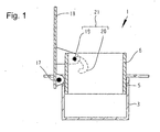
- FIGURE 1 shows a holder according to the invention in a sectional view.
- the holder 1 shown in Figure 1 is intended for installation in a motor vehicle, for example in the area of the center console.
- the holder 1 is used to set a beverage container such as a displayed beverage can.
- the holder 1 has a container receptacle 3.
- the retaining ring 6 is shown in the raised position.
- the lid 18 is attached to the closing of the holder 1 via the pivot bearing 17.
- On the cover 18, a control pin 19 is mounted, which engages in a arranged on the retaining ring 6 control cam 20.
- lid 18 and retaining ring 6 are positively coupled in the form of a link control 21.
- the retaining ring 6 is raised or lowered.
- the retention of the retaining ring 6 in the illustrated raised position can be achieved by appropriate friction conditions in the slide control 21 in the pivot bearing 17 and / or in the guide 5 of the retaining ring 6 in the container receptacle 3.
- a latching mechanism (not shown) may be provided.
Landscapes
- Engineering & Computer Science (AREA)
- Physics & Mathematics (AREA)
- Thermal Sciences (AREA)
- Transportation (AREA)
- Mechanical Engineering (AREA)
- Passenger Equipment (AREA)
- Vehicle Step Arrangements And Article Storage (AREA)
- Filling Of Jars Or Cans And Processes For Cleaning And Sealing Jars (AREA)
Description
- Die Erfindung betrifft einen Halter für einen Getränkebehälter mit den Merkmalen des Oberbegriffs des Anspruchs 1. Der Halter ist für den Einbau in ein Fahrzeug zum Halten von Getränkedosen, Flaschen oder dgl. vorgesehen.
- Aus dem Stand der Technik sind eine Vielzahl derartiger Halter mit einer topfförmigen Behälteraufnahme bekannt. So werden beispielsweise entsprechende Vertiefungen im Bereich der Mittelkonsole von Kraftfahrzeugen angeordnet. Dabei besteht häufig das Problem, dass aufgrund mangelnden Platzes keine ausreichende Einstelltiefe für hohe Getränkebehälter, wie Flaschen, erreicht werden kann.
- Aus der Druckschrift DE 197 52 385 A1 ist ein platzsparender Halter bekannt, bei dem ein Haltering durch eine an einer Behälteraufnahme angeordneten Führung zwischen einer abgesenkten und einer angehobenen Stellung auf- und abbeweglich geführt ist. Am Haltering ist ein Zapfen und an der Behalteaufnahme eine wendelartig umlaufende Nut angeordnet, so dass der Haltering durch Drehung in die abgesenkte bzw. angehobene Stellung verbracht werden kann. Auch in der abgesenkten Position des Halterings besteht eine nach oben offene Vertiefung, was im Bereich der Mittelkonsole aus optischen Gründen unerwünscht sein kann.
- Der Erfindung liegt daher die Aufgabe zugrunde, einen Halter für einen Getränkebehälter zu schaffen, der bei geringem Bauraum eine große Einstelltiefe erreicht und sich bei Nichtbenutzung optisch ansprechend in den umgebenden Bauraum einfügt.
- Diese Aufgabe wird erfindungsgemäß durch die Merkmale des Anspruchs 1 gelöst. Die Erfindung sieht vor, dass die Einstelltiefe der Behälteraufnahme durch einen Haltering vergrößert wird. Der Haltering wird durch eine an der Behälteraufnahme angeordnete Führung zwischen einer abgesenkten und einer angehobenen Stellung geführt. Die Behälteraufnahme benötigt dabei nur eine geringe Tiefe, beispielsweise nur ein Drittel der Höhe einer Getränkedose. Hierdurch ist ein Einbau beispielsweise im Bereich der Mittelkonsole auch bei beengten Platzverhältnissen im Inneren der Mittelkonsole möglich. Gleichzeitig ragt der Haltering in der abgesenkten Position nur kaum oder gar nicht über die den Halter umgebende Blende hinaus und stellt damit kein Hindemis dar. Sehr niedrigen Getränkebehältern, beispielsweise kleinen Pappbechem, gibt der Halter dennoch bereits in dieser abgesenkten Position des Halterings ausreichend Halt. Zum Halten höherer Getränkebehälter wird der Haltering angehoben und gibt in dieser Stellung guten Halt. Neben dem geringen Bauraum ergibt sich damit der Vorteil, dass die Einstelltiefe an unterschiedliche Getränkebehältergrößen anpassbar ist.
- Erfindungsgemäß erfolgt sowohl das anheben als auch das Absenken des Halterings indirekt über einen schwenkend öffenbaren Deckel des Halters. Dazu sind Deckel und Haltering über eine Kulissensteuerung miteinander gekoppelt, wobei am Deckel ein Steuerzapfen angeordnet ist, der in eine Steuerkurve am Haltering eingreift. Durch das Öffnen des Deckels wird der Haltering, geführt durch die Führung an der Behälteraufnahme, nach oben gezogen. Entsprechend umgekehrt wird der Haltering beim Schließen des Deckels abgesenkt.
- Dadurch dass der Deckel einen Halter aufweist, ist die Vertiefung der Behälteraufnahme bei der abgesenkten Stellung des Halterings, d. h. in der Nichtgebrauchsstellung, nicht sichtbar. Der Deckel kann derart geformt sein, dass er der umgebenden Kontur angepasst ist. Durch die Koppelung von Deckel und Haltering muss nicht zuerst der Deckel geöffnet und dann der Haltering angehoben werden, sondern der Haltering wird automatisch in die Gebrauchsstellung gebracht. Dies vereinfacht die Handhabung.
- Die Erfindung wird nachfolgend anhand eines in der Zeichnung dargestellten Ausführungsbeispiels näher erläutert. Die einzige Figur 1 zeigt einen erfindungsgemäßen Halter in Schnittdarstellung.
- Der in Figur 1 dargestellte Halter 1 ist für den Einbau in einen Kraftwagen beispielsweise im Bereich der Mittelkonsole vorgesehen. Der Halter 1 dient dem Einstellen eines Getränkebehälters wie beispielsweise einer dargestellten Getränkedose. Zu dessen Aufnahme weist der Halter 1 eine Behälteraufnahme 3 auf. Der Haltering 6 ist in der angehobenen Stellung dargestellt. An der Behälteraufnahme 3 ist über das Schwenklager 17 der Deckel 18 zum Verschließen des Halters 1 angebracht. Am Deckel 18 ist ein Steuerzapfen 19 angebracht, der in eine am Haltering 6 angeordnete Steuerkurve 20 eingreift. Hierdurch sind Deckel 18 und Haltering 6 in Form einer Kulissensteuerung 21 zwangsgekoppelt. Durch das Öffnen bzw. Schließen des Deckels 18 wird der Haltering 6 angehoben bzw. abgesenkt. Das Verbleiben des Halterings 6 in der dargestellten angehobenen Stellung kann durch entsprechende Reibungsverhältnisse in der Kulissensteuerung 21 im Schwenklager 17 und/oder in der Führung 5 des Halterings 6 in der Behälteraufnahme 3 erreicht werden. Alternativ kann ein Rastmechanismus (nicht dargestellt) vorgesehen werden.
Claims (1)
- Halter (1), mit einer topfförmigen Behälteraufnahme (3) für einen Getränkebehälter, wobei der Halter (1) einen Haltering (6) und eine an der Behälteraufnahme (3) angeordnete Führung (5) aufweist, und wobei die Führung (5) den Haltering (6) zwischen einer abgesenkten und einer angehobenen Stellung auf- und abbeweglich führt, dadurch gekennzeichnet, dass der Halter (1) einen schwenkend offenbaren Deckel (18) aufweist und wobei der Haltering (6) über eine Kulissensteuerung (21) mit einem am Deckel (18) angeordneten Steuerzapfen (19) und einer am Haltering (6) angeordneten Steuerkurve (20) gekoppelt ist.
Applications Claiming Priority (2)
| Application Number | Priority Date | Filing Date | Title |
|---|---|---|---|
| DE10231519 | 2002-07-12 | ||
| DE10231519A DE10231519A1 (de) | 2002-07-12 | 2002-07-12 | Halter für einen Getränkebehälter |
Publications (3)
| Publication Number | Publication Date |
|---|---|
| EP1380466A2 EP1380466A2 (de) | 2004-01-14 |
| EP1380466A3 EP1380466A3 (de) | 2004-07-07 |
| EP1380466B1 true EP1380466B1 (de) | 2006-05-31 |
Family
ID=29723863
Family Applications (1)
| Application Number | Title | Priority Date | Filing Date |
|---|---|---|---|
| EP03014223A Expired - Lifetime EP1380466B1 (de) | 2002-07-12 | 2003-06-25 | Halter für einen Getränkebehälter |
Country Status (5)
| Country | Link |
|---|---|
| US (1) | US20040069792A1 (de) |
| EP (1) | EP1380466B1 (de) |
| JP (1) | JP3887615B2 (de) |
| AT (1) | ATE327923T1 (de) |
| DE (2) | DE10231519A1 (de) |
Cited By (2)
| Publication number | Priority date | Publication date | Assignee | Title |
|---|---|---|---|---|
| WO2013171282A1 (de) | 2012-05-16 | 2013-11-21 | Bos Gmbh & Co. Kg | Aufnahmevorrichtung für wenigstens ein flaschen- oder becherbehältnis in einem fahrzeuginnenraum |
| DE102012208275A1 (de) | 2012-05-16 | 2013-11-21 | Bos Gmbh & Co. Kg | Aufnahmevorrichtung für wenigstens ein Flaschen- oder Becherbehältnis in einem Fahrzeuginnenraum |
Families Citing this family (22)
| Publication number | Priority date | Publication date | Assignee | Title |
|---|---|---|---|---|
| DE20218006U1 (de) * | 2002-11-21 | 2003-01-23 | Reum GmbH & Co. Betriebs KG, 74736 Hardheim | Haltevorrichtung um lösbaren Halten von Gegenständen |
| DE10350118A1 (de) * | 2003-10-28 | 2005-06-09 | Olho-Technik Oleff & Holtmann Ohg | Flaschen- oder Becherhalter für ein Kraftfahrzeug |
| DE102004050286B4 (de) | 2004-10-15 | 2020-03-26 | Fischer Automotive Systems Gmbh & Co. Kg | Halter für einen Getränkebehälter zum Einbau in einem Kraftwagen |
| DE102004060272A1 (de) * | 2004-12-15 | 2006-06-29 | Fischer Automotive Systems Gmbh | Haltevorrichtung für einen Getränkebehälter zum Einbau in einem Kraftwagen |
| FR2886236B1 (fr) * | 2005-05-30 | 2007-08-17 | Faurecia Interieur Ind Snc | Dispositif porte-recipient escamotable pour interieur de vehicule automobile |
| DE102005039266B4 (de) | 2005-08-19 | 2010-02-11 | Dr. Schneider Kunststoffwerke Gmbh | Vorrichtung zum Halten von Getränkedosen, Trinkflaschen und ähnlichen Behältnissen |
| KR100748883B1 (ko) | 2005-11-29 | 2007-08-13 | 현대자동차주식회사 | 확장형 컵 홀더 |
| CA2629964A1 (en) | 2005-11-30 | 2007-06-07 | Astellas Pharma Inc. | 2-aminobenzamide derivative |
| US7438356B2 (en) | 2005-12-29 | 2008-10-21 | Tranquilease, Llc | Portable heated stadium seat and method |
| DE102006027497A1 (de) * | 2006-06-14 | 2007-12-20 | Daimlerchrysler Ag | Halteeinrichtung für Getränkebehälter |
| JP2009040196A (ja) * | 2007-08-08 | 2009-02-26 | Toyoda Gosei Co Ltd | カップホルダ |
| DE102008059252A1 (de) * | 2008-11-27 | 2010-06-02 | GM Global Technology Operations, Inc., Detroit | Kraftfahrzeug mit Konsole, Konsole mit Gefäßhaltevorrichtung und Gefäßhaltevorrichtung |
| DE102011080693A1 (de) | 2011-08-09 | 2013-02-14 | Robert Bosch Gmbh | Magnetanker |
| DE102012222554A1 (de) * | 2012-11-13 | 2014-05-15 | F.S. Fehrer Automotive Gmbh | Trinkgefäßhalter |
| CN103112380B (zh) * | 2013-02-21 | 2015-08-05 | 上海延锋江森座椅有限公司 | 深度可调节杯托 |
| DE102013204000A1 (de) * | 2013-03-08 | 2014-09-11 | Bos Gmbh & Co. Kg | Schwenkbare Lehnenanordnung für einen Fahrzeuginnenraum |
| JP6271381B2 (ja) * | 2014-09-17 | 2018-01-31 | 明和工業株式会社 | カップホルダ |
| JP6361932B2 (ja) * | 2015-05-12 | 2018-07-25 | 豊田合成株式会社 | 昇降式容器ホルダ |
| KR102586932B1 (ko) * | 2018-05-25 | 2023-10-10 | 현대자동차주식회사 | 자동차 시트용 사이드 테이블 어셈블리 |
| USD979335S1 (en) * | 2020-06-18 | 2023-02-28 | Yuanfeng Su | Cup holder for seating |
| CN216833367U (zh) * | 2021-12-29 | 2022-06-28 | 东莞市锦驰电子科技有限公司 | 一种可替换的车载杯架 |
| DE102022210103A1 (de) * | 2022-09-26 | 2024-03-28 | Bos Gmbh & Co. Kg | Behältnisaufnahmevorrichtung für einen Fahrzeuginnenraum |
Family Cites Families (20)
| Publication number | Priority date | Publication date | Assignee | Title |
|---|---|---|---|---|
| US1957293A (en) * | 1930-03-15 | 1934-05-01 | Evans Case Co | Cigarette container construction |
| US1985615A (en) * | 1933-01-11 | 1934-12-25 | Scovill Manufacturing Co | Container |
| US2031115A (en) * | 1934-10-12 | 1936-02-18 | Charles V Lindbloom | Sanitary toothbrush holder |
| US3236588A (en) * | 1962-03-05 | 1966-02-22 | Edwin E Emerson | Thermometer dispenser and sterilizer |
| US3445322A (en) * | 1965-10-18 | 1969-05-20 | Ignatius T Agro | Laminated building component |
| JP2538940Y2 (ja) * | 1991-03-01 | 1997-06-18 | 本田技研工業株式会社 | カップホルダ装置 |
| US5370757A (en) * | 1991-08-30 | 1994-12-06 | Basf Corporation | Process for manufacturing substantially 100% nylon 6 carpet |
| DE4200823A1 (de) * | 1992-01-15 | 1993-07-22 | Bayerische Motoren Werke Ag | Gefaesshalter |
| DE4224700A1 (de) * | 1992-07-25 | 1994-01-27 | Euwe Eugen Wexler Gmbh | Haltevorrichtung für Getränkebehälter |
| FR2703378B1 (fr) * | 1993-03-30 | 1995-06-02 | Pierre Clement | Elément de paroi à isolation dynamique pour le renouvellement d'air dans les bâtiments en vue de les rendre plus confortables et plus économiques. |
| DE19507612A1 (de) * | 1995-03-04 | 1996-09-05 | Fischer Artur Werke Gmbh | Halterung für einen Getränkebehälter |
| US5634621A (en) * | 1995-06-07 | 1997-06-03 | Manchester Plastics, Inc. | Three-stage dual cup holder |
| DE19630528A1 (de) * | 1996-07-29 | 1998-02-05 | Fischer Artur Werke Gmbh | Vorrichtung zum Halten zweier Getränkebehälter in der Mittelkonsole eines Kraftwagens |
| DE19752385A1 (de) * | 1997-11-26 | 1999-05-27 | Volkswagen Ag | Kraftfahrzeug mit mindestens einem auf der Innenseite einer Handschuhkastenverschlußklappe angebrachten Funktionselement |
| JPH11206544A (ja) * | 1998-01-19 | 1999-08-03 | Tatsushi Matsushita | 吸着式カップホルダー |
| DE29812146U1 (de) * | 1998-07-08 | 1998-09-17 | OLHO-TECHNIK Oleff + Hoffmann oHG, 32584 Löhne | In ein Kraftfahrzeug einbaubare Vorrichtung zum Halten eines Trinkgefäßes |
| JP3644581B2 (ja) * | 1999-03-26 | 2005-04-27 | 豊田合成株式会社 | ホルダー |
| US6427960B1 (en) * | 2000-10-07 | 2002-08-06 | Collins & Aikman Products Co. | Container holding assembly |
| DE10062161A1 (de) * | 2000-12-14 | 2002-06-20 | Volkswagen Ag | Handschuhkastendeckel |
| DE10101642A1 (de) * | 2001-01-16 | 2002-07-25 | Faurecia Autositze Gmbh & Co | Fahrzeughalter für Flüssigkeitsbehälter |
-
2002
- 2002-07-12 DE DE10231519A patent/DE10231519A1/de not_active Withdrawn
-
2003
- 2003-06-25 DE DE50303549T patent/DE50303549D1/de not_active Expired - Lifetime
- 2003-06-25 EP EP03014223A patent/EP1380466B1/de not_active Expired - Lifetime
- 2003-06-25 AT AT03014223T patent/ATE327923T1/de not_active IP Right Cessation
- 2003-07-10 JP JP2003195256A patent/JP3887615B2/ja not_active Expired - Fee Related
- 2003-07-11 US US10/617,973 patent/US20040069792A1/en not_active Abandoned
Cited By (3)
| Publication number | Priority date | Publication date | Assignee | Title |
|---|---|---|---|---|
| WO2013171282A1 (de) | 2012-05-16 | 2013-11-21 | Bos Gmbh & Co. Kg | Aufnahmevorrichtung für wenigstens ein flaschen- oder becherbehältnis in einem fahrzeuginnenraum |
| DE102012208275A1 (de) | 2012-05-16 | 2013-11-21 | Bos Gmbh & Co. Kg | Aufnahmevorrichtung für wenigstens ein Flaschen- oder Becherbehältnis in einem Fahrzeuginnenraum |
| DE102012208278A1 (de) | 2012-05-16 | 2013-11-21 | Bos Gmbh & Co. Kg | Aufnahmevorrichtung für wenigstens ein Flaschen- oder Becherbehältnis in einem Fahrzeuginnenraum |
Also Published As
| Publication number | Publication date |
|---|---|
| DE50303549D1 (de) | 2006-07-06 |
| ATE327923T1 (de) | 2006-06-15 |
| EP1380466A3 (de) | 2004-07-07 |
| US20040069792A1 (en) | 2004-04-15 |
| EP1380466A2 (de) | 2004-01-14 |
| JP3887615B2 (ja) | 2007-02-28 |
| JP2004042895A (ja) | 2004-02-12 |
| DE10231519A1 (de) | 2004-01-22 |
Similar Documents
| Publication | Publication Date | Title |
|---|---|---|
| EP1380466B1 (de) | Halter für einen Getränkebehälter | |
| EP0697308B1 (de) | Vorrichtung zum Halten von zwei Getränkebehältnissen in der Mittelkonsole eines Kraftfahrzeuges | |
| EP1093962B1 (de) | Halter für einen Getränkebehälter | |
| EP1300281B1 (de) | Halter für einen Getränkebehälter | |
| EP1255662B1 (de) | Halterung für getränkebehälter | |
| DE102019116123B4 (de) | Behälterhalter mit Rückhalteelementen zur Sicherung eines Behälters | |
| EP0756965A2 (de) | Halterung für zwei Getränkebehälter | |
| DE29812146U1 (de) | In ein Kraftfahrzeug einbaubare Vorrichtung zum Halten eines Trinkgefäßes | |
| DE102014218412B4 (de) | Ablagefach mit Halterung | |
| DE10032657C2 (de) | Mittelkonsole in einem Kraftfahrzeuginnenraum | |
| DE102012208275A1 (de) | Aufnahmevorrichtung für wenigstens ein Flaschen- oder Becherbehältnis in einem Fahrzeuginnenraum | |
| EP1138549B1 (de) | Halterung für einen Getränkebehälter | |
| WO2008055555A1 (de) | Staufach mit einer abdeckeinrichtung | |
| EP0745037B1 (de) | Haltevorrichtung für flüssigkeitsbehälter, insbesondere zum einbau in kraftfahrzeuge | |
| DE10112649A1 (de) | In ein Kraftfahrzeug einbaubarer Becherhalter | |
| DE3700614A1 (de) | Telefonarmlehne fuer fahrzeuge, insbes. personenkraftwagen | |
| DE10016463A1 (de) | Halter für einen Getränkebehälter | |
| DE102009009527A1 (de) | Ablagefach | |
| DE19749366A1 (de) | Vorrichtung zum Haltern von Getränkebehältnissen | |
| DE102005019035B4 (de) | Halter für Getränkebehälter | |
| DE10138292B4 (de) | Konsole mit Getränkehaltern mit einem Schubladenprinzip | |
| DE4228848C1 (de) | Haltevorrichtung für Getränkeflaschen an einem Fahrzeugsitz mit Armlehne | |
| EP1258392B1 (de) | Gefässhalter, insbesondere als Innenausstattung für Fahrzeuge | |
| DE20308296U1 (de) | Ablagefach | |
| EP1103416B1 (de) | Halter für einen Getränkebehälter in einem Kraftwagen |
Legal Events
| Date | Code | Title | Description |
|---|---|---|---|
| PUAI | Public reference made under article 153(3) epc to a published international application that has entered the european phase |
Free format text: ORIGINAL CODE: 0009012 |
|
| AK | Designated contracting states |
Kind code of ref document: A2 Designated state(s): AT BE BG CH CY CZ DE DK EE ES FI FR GB GR HU IE IT LI LU MC NL PT RO SE SI SK TR |
|
| AX | Request for extension of the european patent |
Extension state: AL LT LV MK |
|
| PUAL | Search report despatched |
Free format text: ORIGINAL CODE: 0009013 |
|
| AK | Designated contracting states |
Kind code of ref document: A3 Designated state(s): AT BE BG CH CY CZ DE DK EE ES FI FR GB GR HU IE IT LI LU MC NL PT RO SE SI SK TR |
|
| AX | Request for extension of the european patent |
Extension state: AL LT LV MK |
|
| 17P | Request for examination filed |
Effective date: 20041111 |
|
| 17Q | First examination report despatched |
Effective date: 20050131 |
|
| AKX | Designation fees paid |
Designated state(s): AT BE BG CH CY CZ DE DK EE ES FI FR GB GR HU IE IT LI LU MC NL PT RO SE SI SK TR |
|
| GRAP | Despatch of communication of intention to grant a patent |
Free format text: ORIGINAL CODE: EPIDOSNIGR1 |
|
| GRAS | Grant fee paid |
Free format text: ORIGINAL CODE: EPIDOSNIGR3 |
|
| GRAA | (expected) grant |
Free format text: ORIGINAL CODE: 0009210 |
|
| AK | Designated contracting states |
Kind code of ref document: B1 Designated state(s): AT BE BG CH CY CZ DE DK EE ES FI FR GB GR HU IE IT LI LU MC NL PT RO SE SI SK TR |
|
| PG25 | Lapsed in a contracting state [announced via postgrant information from national office to epo] |
Ref country code: IT Free format text: LAPSE BECAUSE OF FAILURE TO SUBMIT A TRANSLATION OF THE DESCRIPTION OR TO PAY THE FEE WITHIN THE PRESCRIBED TIME-LIMIT;WARNING: LAPSES OF ITALIAN PATENTS WITH EFFECTIVE DATE BEFORE 2007 MAY HAVE OCCURRED AT ANY TIME BEFORE 2007. THE CORRECT EFFECTIVE DATE MAY BE DIFFERENT FROM THE ONE RECORDED. Effective date: 20060531 Ref country code: SI Free format text: LAPSE BECAUSE OF FAILURE TO SUBMIT A TRANSLATION OF THE DESCRIPTION OR TO PAY THE FEE WITHIN THE PRESCRIBED TIME-LIMIT Effective date: 20060531 Ref country code: NL Free format text: LAPSE BECAUSE OF FAILURE TO SUBMIT A TRANSLATION OF THE DESCRIPTION OR TO PAY THE FEE WITHIN THE PRESCRIBED TIME-LIMIT Effective date: 20060531 Ref country code: RO Free format text: LAPSE BECAUSE OF FAILURE TO SUBMIT A TRANSLATION OF THE DESCRIPTION OR TO PAY THE FEE WITHIN THE PRESCRIBED TIME-LIMIT Effective date: 20060531 Ref country code: FI Free format text: LAPSE BECAUSE OF FAILURE TO SUBMIT A TRANSLATION OF THE DESCRIPTION OR TO PAY THE FEE WITHIN THE PRESCRIBED TIME-LIMIT Effective date: 20060531 Ref country code: CZ Free format text: LAPSE BECAUSE OF FAILURE TO SUBMIT A TRANSLATION OF THE DESCRIPTION OR TO PAY THE FEE WITHIN THE PRESCRIBED TIME-LIMIT Effective date: 20060531 Ref country code: SK Free format text: LAPSE BECAUSE OF FAILURE TO SUBMIT A TRANSLATION OF THE DESCRIPTION OR TO PAY THE FEE WITHIN THE PRESCRIBED TIME-LIMIT Effective date: 20060531 Ref country code: IE Free format text: LAPSE BECAUSE OF FAILURE TO SUBMIT A TRANSLATION OF THE DESCRIPTION OR TO PAY THE FEE WITHIN THE PRESCRIBED TIME-LIMIT Effective date: 20060531 |
|
| REG | Reference to a national code |
Ref country code: GB Ref legal event code: FG4D Free format text: NOT ENGLISH Ref country code: CH Ref legal event code: EP |
|
| REG | Reference to a national code |
Ref country code: IE Ref legal event code: FG4D Free format text: LANGUAGE OF EP DOCUMENT: GERMAN |
|
| PG25 | Lapsed in a contracting state [announced via postgrant information from national office to epo] |
Ref country code: BE Free format text: LAPSE BECAUSE OF NON-PAYMENT OF DUE FEES Effective date: 20060630 Ref country code: MC Free format text: LAPSE BECAUSE OF NON-PAYMENT OF DUE FEES Effective date: 20060630 |
|
| REF | Corresponds to: |
Ref document number: 50303549 Country of ref document: DE Date of ref document: 20060706 Kind code of ref document: P |
|
| PG25 | Lapsed in a contracting state [announced via postgrant information from national office to epo] |
Ref country code: DK Free format text: LAPSE BECAUSE OF FAILURE TO SUBMIT A TRANSLATION OF THE DESCRIPTION OR TO PAY THE FEE WITHIN THE PRESCRIBED TIME-LIMIT Effective date: 20060831 Ref country code: SE Free format text: LAPSE BECAUSE OF FAILURE TO SUBMIT A TRANSLATION OF THE DESCRIPTION OR TO PAY THE FEE WITHIN THE PRESCRIBED TIME-LIMIT Effective date: 20060831 |
|
| PG25 | Lapsed in a contracting state [announced via postgrant information from national office to epo] |
Ref country code: ES Free format text: LAPSE BECAUSE OF FAILURE TO SUBMIT A TRANSLATION OF THE DESCRIPTION OR TO PAY THE FEE WITHIN THE PRESCRIBED TIME-LIMIT Effective date: 20060911 |
|
| GBT | Gb: translation of ep patent filed (gb section 77(6)(a)/1977) |
Effective date: 20060925 |
|
| PG25 | Lapsed in a contracting state [announced via postgrant information from national office to epo] |
Ref country code: PT Free format text: LAPSE BECAUSE OF FAILURE TO SUBMIT A TRANSLATION OF THE DESCRIPTION OR TO PAY THE FEE WITHIN THE PRESCRIBED TIME-LIMIT Effective date: 20061031 |
|
| NLV1 | Nl: lapsed or annulled due to failure to fulfill the requirements of art. 29p and 29m of the patents act | ||
| ET | Fr: translation filed | ||
| REG | Reference to a national code |
Ref country code: IE Ref legal event code: FD4D |
|
| PLBE | No opposition filed within time limit |
Free format text: ORIGINAL CODE: 0009261 |
|
| STAA | Information on the status of an ep patent application or granted ep patent |
Free format text: STATUS: NO OPPOSITION FILED WITHIN TIME LIMIT |
|
| 26N | No opposition filed |
Effective date: 20070301 |
|
| PG25 | Lapsed in a contracting state [announced via postgrant information from national office to epo] |
Ref country code: AT Free format text: LAPSE BECAUSE OF NON-PAYMENT OF DUE FEES Effective date: 20060625 |
|
| BERE | Be: lapsed |
Owner name: FISCHER AUTOMOTIVE SYSTEMS G.M.B.H. Effective date: 20060630 |
|
| REG | Reference to a national code |
Ref country code: CH Ref legal event code: PL |
|
| PG25 | Lapsed in a contracting state [announced via postgrant information from national office to epo] |
Ref country code: GR Free format text: LAPSE BECAUSE OF FAILURE TO SUBMIT A TRANSLATION OF THE DESCRIPTION OR TO PAY THE FEE WITHIN THE PRESCRIBED TIME-LIMIT Effective date: 20060901 Ref country code: CH Free format text: LAPSE BECAUSE OF NON-PAYMENT OF DUE FEES Effective date: 20070630 Ref country code: LI Free format text: LAPSE BECAUSE OF NON-PAYMENT OF DUE FEES Effective date: 20070630 |
|
| PG25 | Lapsed in a contracting state [announced via postgrant information from national office to epo] |
Ref country code: BG Free format text: LAPSE BECAUSE OF FAILURE TO SUBMIT A TRANSLATION OF THE DESCRIPTION OR TO PAY THE FEE WITHIN THE PRESCRIBED TIME-LIMIT Effective date: 20060831 Ref country code: EE Free format text: LAPSE BECAUSE OF FAILURE TO SUBMIT A TRANSLATION OF THE DESCRIPTION OR TO PAY THE FEE WITHIN THE PRESCRIBED TIME-LIMIT Effective date: 20060531 |
|
| PG25 | Lapsed in a contracting state [announced via postgrant information from national office to epo] |
Ref country code: HU Free format text: LAPSE BECAUSE OF FAILURE TO SUBMIT A TRANSLATION OF THE DESCRIPTION OR TO PAY THE FEE WITHIN THE PRESCRIBED TIME-LIMIT Effective date: 20061201 Ref country code: LU Free format text: LAPSE BECAUSE OF NON-PAYMENT OF DUE FEES Effective date: 20060625 Ref country code: TR Free format text: LAPSE BECAUSE OF FAILURE TO SUBMIT A TRANSLATION OF THE DESCRIPTION OR TO PAY THE FEE WITHIN THE PRESCRIBED TIME-LIMIT Effective date: 20060531 |
|
| PG25 | Lapsed in a contracting state [announced via postgrant information from national office to epo] |
Ref country code: CY Free format text: LAPSE BECAUSE OF FAILURE TO SUBMIT A TRANSLATION OF THE DESCRIPTION OR TO PAY THE FEE WITHIN THE PRESCRIBED TIME-LIMIT Effective date: 20060531 |
|
| PGFP | Annual fee paid to national office [announced via postgrant information from national office to epo] |
Ref country code: FR Payment date: 20090615 Year of fee payment: 7 |
|
| PGFP | Annual fee paid to national office [announced via postgrant information from national office to epo] |
Ref country code: GB Payment date: 20090618 Year of fee payment: 7 |
|
| GBPC | Gb: european patent ceased through non-payment of renewal fee |
Effective date: 20100625 |
|
| REG | Reference to a national code |
Ref country code: FR Ref legal event code: ST Effective date: 20110228 |
|
| PG25 | Lapsed in a contracting state [announced via postgrant information from national office to epo] |
Ref country code: FR Free format text: LAPSE BECAUSE OF NON-PAYMENT OF DUE FEES Effective date: 20100630 |
|
| PG25 | Lapsed in a contracting state [announced via postgrant information from national office to epo] |
Ref country code: GB Free format text: LAPSE BECAUSE OF NON-PAYMENT OF DUE FEES Effective date: 20100625 |
|
| PGFP | Annual fee paid to national office [announced via postgrant information from national office to epo] |
Ref country code: DE Payment date: 20130416 Year of fee payment: 11 |
|
| REG | Reference to a national code |
Ref country code: DE Ref legal event code: R119 Ref document number: 50303549 Country of ref document: DE |
|
| REG | Reference to a national code |
Ref country code: DE Ref legal event code: R119 Ref document number: 50303549 Country of ref document: DE Effective date: 20150101 |
|
| PG25 | Lapsed in a contracting state [announced via postgrant information from national office to epo] |
Ref country code: DE Free format text: LAPSE BECAUSE OF NON-PAYMENT OF DUE FEES Effective date: 20150101 |