EP1383650B1 - Tubular polymeric composites for tubing and hose constructions - Google Patents
Tubular polymeric composites for tubing and hose constructions Download PDFInfo
- Publication number
- EP1383650B1 EP1383650B1 EP02753873A EP02753873A EP1383650B1 EP 1383650 B1 EP1383650 B1 EP 1383650B1 EP 02753873 A EP02753873 A EP 02753873A EP 02753873 A EP02753873 A EP 02753873A EP 1383650 B1 EP1383650 B1 EP 1383650B1
- Authority
- EP
- European Patent Office
- Prior art keywords
- layer
- article
- thermoplastic material
- mole
- copolymer
- Prior art date
- Legal status (The legal status is an assumption and is not a legal conclusion. Google has not performed a legal analysis and makes no representation as to the accuracy of the status listed.)
- Revoked
Links
Images

Classifications
-
- B—PERFORMING OPERATIONS; TRANSPORTING
- B32—LAYERED PRODUCTS
- B32B—LAYERED PRODUCTS, i.e. PRODUCTS BUILT-UP OF STRATA OF FLAT OR NON-FLAT, e.g. CELLULAR OR HONEYCOMB, FORM
- B32B1/00—Layered products having a non-planar shape
- B32B1/08—Tubular products
-
- B—PERFORMING OPERATIONS; TRANSPORTING
- B32—LAYERED PRODUCTS
- B32B—LAYERED PRODUCTS, i.e. PRODUCTS BUILT-UP OF STRATA OF FLAT OR NON-FLAT, e.g. CELLULAR OR HONEYCOMB, FORM
- B32B27/00—Layered products comprising a layer of synthetic resin
- B32B27/06—Layered products comprising a layer of synthetic resin as the main or only constituent of a layer, which is next to another layer of the same or of a different material
- B32B27/08—Layered products comprising a layer of synthetic resin as the main or only constituent of a layer, which is next to another layer of the same or of a different material of synthetic resin
-
- B—PERFORMING OPERATIONS; TRANSPORTING
- B32—LAYERED PRODUCTS
- B32B—LAYERED PRODUCTS, i.e. PRODUCTS BUILT-UP OF STRATA OF FLAT OR NON-FLAT, e.g. CELLULAR OR HONEYCOMB, FORM
- B32B27/00—Layered products comprising a layer of synthetic resin
- B32B27/12—Layered products comprising a layer of synthetic resin next to a fibrous or filamentary layer
-
- B—PERFORMING OPERATIONS; TRANSPORTING
- B32—LAYERED PRODUCTS
- B32B—LAYERED PRODUCTS, i.e. PRODUCTS BUILT-UP OF STRATA OF FLAT OR NON-FLAT, e.g. CELLULAR OR HONEYCOMB, FORM
- B32B27/00—Layered products comprising a layer of synthetic resin
- B32B27/28—Layered products comprising a layer of synthetic resin comprising synthetic resins not wholly covered by any one of the sub-groups B32B27/30 - B32B27/42
-
- B—PERFORMING OPERATIONS; TRANSPORTING
- B32—LAYERED PRODUCTS
- B32B—LAYERED PRODUCTS, i.e. PRODUCTS BUILT-UP OF STRATA OF FLAT OR NON-FLAT, e.g. CELLULAR OR HONEYCOMB, FORM
- B32B27/00—Layered products comprising a layer of synthetic resin
- B32B27/34—Layered products comprising a layer of synthetic resin comprising polyamides
-
- B—PERFORMING OPERATIONS; TRANSPORTING
- B32—LAYERED PRODUCTS
- B32B—LAYERED PRODUCTS, i.e. PRODUCTS BUILT-UP OF STRATA OF FLAT OR NON-FLAT, e.g. CELLULAR OR HONEYCOMB, FORM
- B32B37/00—Methods or apparatus for laminating, e.g. by curing or by ultrasonic bonding
- B32B37/14—Methods or apparatus for laminating, e.g. by curing or by ultrasonic bonding characterised by the properties of the layers
- B32B37/15—Methods or apparatus for laminating, e.g. by curing or by ultrasonic bonding characterised by the properties of the layers with at least one layer being manufactured and immediately laminated before reaching its stable state, e.g. in which a layer is extruded and laminated while in semi-molten state
- B32B37/153—Methods or apparatus for laminating, e.g. by curing or by ultrasonic bonding characterised by the properties of the layers with at least one layer being manufactured and immediately laminated before reaching its stable state, e.g. in which a layer is extruded and laminated while in semi-molten state at least one layer is extruded and immediately laminated while in semi-molten state
-
- F—MECHANICAL ENGINEERING; LIGHTING; HEATING; WEAPONS; BLASTING
- F16—ENGINEERING ELEMENTS AND UNITS; GENERAL MEASURES FOR PRODUCING AND MAINTAINING EFFECTIVE FUNCTIONING OF MACHINES OR INSTALLATIONS; THERMAL INSULATION IN GENERAL
- F16L—PIPES; JOINTS OR FITTINGS FOR PIPES; SUPPORTS FOR PIPES, CABLES OR PROTECTIVE TUBING; MEANS FOR THERMAL INSULATION IN GENERAL
- F16L11/00—Hoses, i.e. flexible pipes
- F16L11/04—Hoses, i.e. flexible pipes made of rubber or flexible plastics
-
- F—MECHANICAL ENGINEERING; LIGHTING; HEATING; WEAPONS; BLASTING
- F16—ENGINEERING ELEMENTS AND UNITS; GENERAL MEASURES FOR PRODUCING AND MAINTAINING EFFECTIVE FUNCTIONING OF MACHINES OR INSTALLATIONS; THERMAL INSULATION IN GENERAL
- F16L—PIPES; JOINTS OR FITTINGS FOR PIPES; SUPPORTS FOR PIPES, CABLES OR PROTECTIVE TUBING; MEANS FOR THERMAL INSULATION IN GENERAL
- F16L11/00—Hoses, i.e. flexible pipes
- F16L11/04—Hoses, i.e. flexible pipes made of rubber or flexible plastics
- F16L11/045—Hoses, i.e. flexible pipes made of rubber or flexible plastics with four or more layers without reinforcement
-
- F—MECHANICAL ENGINEERING; LIGHTING; HEATING; WEAPONS; BLASTING
- F16—ENGINEERING ELEMENTS AND UNITS; GENERAL MEASURES FOR PRODUCING AND MAINTAINING EFFECTIVE FUNCTIONING OF MACHINES OR INSTALLATIONS; THERMAL INSULATION IN GENERAL
- F16L—PIPES; JOINTS OR FITTINGS FOR PIPES; SUPPORTS FOR PIPES, CABLES OR PROTECTIVE TUBING; MEANS FOR THERMAL INSULATION IN GENERAL
- F16L11/00—Hoses, i.e. flexible pipes
- F16L11/04—Hoses, i.e. flexible pipes made of rubber or flexible plastics
- F16L11/08—Hoses, i.e. flexible pipes made of rubber or flexible plastics with reinforcements embedded in the wall
- F16L11/081—Hoses, i.e. flexible pipes made of rubber or flexible plastics with reinforcements embedded in the wall comprising one or more layers of a helically wound cord or wire
- F16L11/082—Hoses, i.e. flexible pipes made of rubber or flexible plastics with reinforcements embedded in the wall comprising one or more layers of a helically wound cord or wire two layers
-
- B—PERFORMING OPERATIONS; TRANSPORTING
- B32—LAYERED PRODUCTS
- B32B—LAYERED PRODUCTS, i.e. PRODUCTS BUILT-UP OF STRATA OF FLAT OR NON-FLAT, e.g. CELLULAR OR HONEYCOMB, FORM
- B32B2250/00—Layers arrangement
- B32B2250/24—All layers being polymeric
-
- B—PERFORMING OPERATIONS; TRANSPORTING
- B32—LAYERED PRODUCTS
- B32B—LAYERED PRODUCTS, i.e. PRODUCTS BUILT-UP OF STRATA OF FLAT OR NON-FLAT, e.g. CELLULAR OR HONEYCOMB, FORM
- B32B2307/00—Properties of the layers or laminate
- B32B2307/70—Other properties
- B32B2307/714—Inert, i.e. inert to chemical degradation, corrosion
-
- B—PERFORMING OPERATIONS; TRANSPORTING
- B32—LAYERED PRODUCTS
- B32B—LAYERED PRODUCTS, i.e. PRODUCTS BUILT-UP OF STRATA OF FLAT OR NON-FLAT, e.g. CELLULAR OR HONEYCOMB, FORM
- B32B2377/00—Polyamides
-
- B—PERFORMING OPERATIONS; TRANSPORTING
- B32—LAYERED PRODUCTS
- B32B—LAYERED PRODUCTS, i.e. PRODUCTS BUILT-UP OF STRATA OF FLAT OR NON-FLAT, e.g. CELLULAR OR HONEYCOMB, FORM
- B32B2597/00—Tubular articles, e.g. hoses, pipes
-
- B—PERFORMING OPERATIONS; TRANSPORTING
- B32—LAYERED PRODUCTS
- B32B—LAYERED PRODUCTS, i.e. PRODUCTS BUILT-UP OF STRATA OF FLAT OR NON-FLAT, e.g. CELLULAR OR HONEYCOMB, FORM
- B32B2605/00—Vehicles
Definitions
- the present invention relates broadly to two or more layer tubular polymeric laminates or composites and to articles such as tubing and hoses constructed thereof, and more particularly to tubular polymeric laminates or composites formed of a layer of a thermoplastic fluoropolymer material bonded directly to a layer of a more general purpose thermoplastic resin material which may be a nylon or other polyamide.
- Fluoropolymers are known to exhibit exceptional resistance to chemical degradation and vapor permeation. Accordingly, these materials are desirable for use as liners in tubing, hoses, and other conduits such as for conveying fuel or fuel vapor in automotive, aerospace, or marine applications, or for conveying petroleum and other hydrocarbons and organic or inorganic solvents in a variety of transport, motion control, natural resource recovery, and chemical process applications.
- fluoropolymers also known to have low surface energies and high electronegativites which, although contributing to the lubricity and "non-stick" properties of such materials, often makes the bonding of other materials thereto difficult.
- the tie layer which may be formed as a co- or tri-extrusion with the liner and second layers, is formulated to be compatible chemically with both the fluoropolymer material of the liner and the material of the second layer such that a thermal fusion bond may be achieved between the liner and tie layer and the tie layer and second layer to thereby consolidate the tubing into an integral structure.
- tie layers dictates the selection of specific materials for the liner and second layer so as to be compatible with the material of the tie layer, or vice versa, and is believed limited to the use of melt processible fluoropolymers such as polyvinylidene fluoride (PVDF) or ethylene tetraflurorethylene (ETFE).
- PVDF polyvinylidene fluoride
- ETFE ethylene tetraflurorethylene
- modified fluoropolymer materials which may be fusion bonded, such as by co-extrusion or molding, to polyamides and epoxies. Such materials are formulated as a fluororesin copolymer having terminal carbonate end groups.
- the fluororesin copolymer may comprise, based on the copolymer, between about 30-81 mole % of a tetrafluoroethylene (TFE) monomer, and about 19-70 mole % of at least one other monomer.
- TFE tetrafluoroethylene
- a preferred composition is a terpolymer of about 40-81 mole % TFE, 6-43 mole % ethylene, and 10-30 mole % of hexafluoropropylene (HFP), and in that regard may be characterized as a modified ethylene tetraflurorethylene (ETFE) copolymer or as an "EFEP" (ethylene-perfluoroethylene) copolymer.
- EFE modified ethylene tetraflurorethylene copolymer
- the composition also may contain 0-10 mole % of a fluorovinyl compound.
- the carbonate end groups which may be incorporated into the copolymer chains by the use of a peroxycarbonate polymerization initiator, may be considered an activator in having a high reactivity with the polyamides bonds and/or terminal amino or carboxyl groups of materials such as polyamides.
- these modified fluoropolymer materials are able to be fusion bonded, such as by co-extrusion or molding, to a general purpose resin such as a polyamide or epoxy at a temperature below the thermal decomposition temperature of the resin, and preferably at a temperature within the range of between about 150-260°C other otherwise within the range of the preferred fusion bonding temperature of the resin.
- the fluororesin copolymer may be formulated to have a melt viscosity which allows flow of the copolymer within such temperature range.
- Modified fluoropolymer materials of the above-described type are sold commercially by Daikin America, Inc. (Orangeburg, NY) under the designations Neoflon TM RP-5000 and RP-5000AS Series.
- Publication FR-A-2689956 describes a fuel transport hose having a fluorine resin inner layer and a polyamide or polyester outer layer.
- Publication WO-A-9314933 describes a laminar film formed of a layer of tetrafluoroethylene copolymer and a layer of a polyimide.
- Publication US-A-5662975 describes a theromplastic tube having an inner surface which is coated with an inner layer of polyvinylidene fluoride.
- Publication US-A-4603712 describes a reinforced, vulcanized elastomeric hose having a tube which may be a fluoroplastic , an outer cover, and a reinforcement layer.
- tubular polymeric composites of two or more layers including a fluororesin layer fusion bonded directly to a nylon or other amide or general purpose resin layer would be useful as elements in a variety of hose and tubing constructions.
- hoses and tubing of the type herein involved may be exposed to a variety of environmental factors and mechanical stresses that cannot always be predicted. It is anticipated, therefore, that tubing and hose constructions which offer chemical and/or moisture resistance, but which are still economical would be well-received by numerous industries for use in high pressure and other fluid transfer and motion control applications.
- a two or more layer tabular composite may be formed by fusion bonding, such as by extrusion, co-extrusion, or molding.
- a layer of a thermoplastic fluoropolymer material which may be bonded directly, i.e., without the use of an adhesive or tie layer, to a layer of a more general purpose thermoplastic resin material which may be a nylon or other polyamide
- the composite of the invention is particularly adapted for use as a core tube in a reinforced hose construction, and as tubing for vehicular airbrake systems and other applications requiring chemical and/or environmental resistance.
- the fluoropolymer material layer which may be both chemically and environmentally-resistant, is provided as an outermost layer of the composite structure or member and of the article constructed thereof.
- the composite structure of the invention may be formed as having an outer fluoropolymer layer, and an inner nylon or other resin layer bonded directly to the fluoropolymer layer.
- the structure so formed may be used as a core tube over which one or more layers of a fibrous reinforcement layer are braided or wound to provide resistance to internal pressure, such as in the case of a medium or high pressure, i.e., 150-60,000 psi (1-413 MPa), hose construction, or to external pressure such as in the case of a collapse-resistant hose for oil recovery, vacuum, or other applications.
- the composite structure of the invention as formed as having an outer fluoropolymer layer, alternatively or in addition to the core tube may be provided between a cover, which itself may be the nylon or other resin layer of the composite or a polyurethane or other layer surrounding the composite, and the reinforcement layers of the hose so as to provide resistance to the penetration of external moisture or chemicals.
- the composite structure of the invention may be formed as having an inner nylon or other resin layer, which may be reinforced or unreinforced, and an outer fluoropolymer layer bonded directly to the resin layer.
- the structure so formed may be used, either as coiled or uncoiled, as tubing such as for tractor/trailer airbrake systems.
- the outer fluoropolymer layer of the composite structure may form the outermost layer of the tubing and thereby provide external chemical resistance such as against methanol and other solvents and corrodants which may be used in the cleaning of the vehicle.
- the present invention accordingly, comprises the structures and article constructed thereof possessing the combination of elements which are exemplified in the detailed disclosure to follow.
- Advantages of the present invention include a tubular composite structure which may be used alone as tubing or as core tube in combination with other materials in a multitude of hose arrangements to provide resistance to internal and/or external chemicals and moisture.
- the precepts of the two or more layer tubular polymeric composite or laminate of the invention herein involved are described in connection with its utilization as a core tube or other member within a flexible pressure or vacuum hose construction such as for fuel transfer, oil or other natural resource recovery, chemical or pharmaceutical processing, or other applications requiring chemical or environmental resistance, or for use by itself as flexible tubing such as for airbrake applications.
- a flexible pressure or vacuum hose construction such as for fuel transfer, oil or other natural resource recovery, chemical or pharmaceutical processing, or other applications requiring chemical or environmental resistance, or for use by itself as flexible tubing such as for airbrake applications.
- aspects of the present invention may find use in other hose and tubing constructions in other fluid transfer applications, and in a variety of hydraulic or pneumatic power or control applications. Use within those such other applications therefore should be considered to be expressly within the scope of the present invention.
- member 10 has an outer circumferential surface, 12, and an inner circumferential surface, 14, and is formed of as a laminate of a tubular first layer, 16, and a tubular second layer, 18, which is concentric with and integrally adjoins the first layer 16.
- the member outer surface 12 is shown to be formed of the first layer 16, and the member inner surface 14 is shown to be formed of the second layer 18, the relative orientation of the layers may be reversed as shown in Fig.3, in accordance with an embodiment of the invention, such that the outer surface 12 is formed of the second layer 18, and the inner surface 14 is formed of the first layer 16.
- the outer and inner surfaces 12 and 14 are shown to be, respectively, the innermost and outermost surfaces of the member 10, it will be appreciated that in a multi-layer structure of member 10, one or more additional layers may be provided to surround the member outer surface 12, and/or one or more additional layers may be provided to be surrounded by the member inner surface 14.
- each of the layers 16 and 18 may be of any thickness, both absolute and relative to the thickness of the other layer, but for many applications, and as maybe irrespective of which of the layers 16 and 18 forms the outer surface 12 and which forms the inner surface 14, the first layer 16 may be relatively thick as having a thickness, referenced at "t 1 ", of between about 0.025-0.25 inch (0.63- 6.4 mm), with second layer 18 being relatively thin as having a thickness, referenced at "t2", of between about 0.001-0.1 inch (0.02-2.50 mm).
- the wall thickness t 2 of the second layer 18 may be maintained at the minimum necessary to provide the desired solvent, gas, or liquid permeation resistance, while for strength and flexibility considerations, the thickness t 1 of the first layer 16 will be 1.25-75 times thicker than the thickness t 2 .
- member 10 may be of any diametric and lengthwise extent, and may be generally round in cross-section as shown, but alternatively may be of an elliptical, polygonal, or other geometric cross-section.
- the first layer 16 is formed of a first thermoplastic material
- the second layer 18 is formed of a second thermoplastic material different from the first material.
- the outer surface of the first layer 16 itself, and the inner surface of the second layer 18 itself are directly bonded together, i.e., without the use of an intermediate tie-layer or adhesive, and also generally without preparation, priming, or other or treatment of surfaces so as to allow the member 10 to be formed by a continuous co-extrusion or other extrusion such as cross-head or sequential extrusion, in addition to molding or co-molding, or other processes such as coating, or a combination of extrusion, molding, and/or coating.
- a thermal "fusion" bond may be formed therebetween, such as by the intermingling of melt material from the layers.
- the bond formed therebetween the layers 16 and 18 generally will depend upon the respective compositions thereof, but may consist of one or more components which may be chemical, such as by covalent, ionic, or hydrogen bonding or cross-linking reactions, electrostatic, van der Waals, or other attractive forces, or mechanical, such as by chain intermingling, in nature.
- an integral, cohesive fusion bond or "weld” is formed between the layers 16 and 18 which generally may have a bond strength, such as a peel strength, of between about 3.5-110 pounds per linear inch (pli) (5.25-192.6 Newtons per linear centimeter (N/cm)).
- pli pounds per linear inch
- N/cm Newtons per linear centimeter
- First layer 16 may be formed of any thermoplastic material, which may be filled or unfilled, but for reasons of cost typically will be a general purpose resin.
- thermoplastic material is used interchangeably with “melt processible material,” and is in contrast to non-melt processible materials such as thermosets or non-thermosetting materials which otherwise exhibit a melt viscosity that is sufficiently high so as to preclude flow and processing by conventional melt extrusion or molding operations, and therefore necessitating that the material be processed using sintering or solvent processing techniques.
- Such general purpose resin materials include polyamides, polyolefins, polyesters, polyvinyl chlorides, ethylene vinyl alcohols (EVA), polyacetals, polyoxymethylenes (POM), silicones, thermoplastic rubbers (TPR) such as polyolefin-ethylene-propylene-diene monomer (EPDM) and other blends, copolymer rubbers, thermoplastic polyurethanes (TPU) and other thermoplastic elastomers (TPE), and blends of any of the foregoing.
- Such resins typically will have a melting point of between about 110-230°C, and a thermal decomposition temperature, which defines the upper processing limit of the resin, of between about 150-260°C.
- melting point may be a transition from a form-stable crystalline or glassy solid phase to a softened or otherwise viscous phase which may be generally characterized as exhibiting intermolecular chain rotation and, as between layers, chain diffusion and/or other intermingling.
- melting point also is used interchangeably with glass transition or softening point.
- a polyamide and, particularly, a plasticized or unplasticized nylon such as Nylon 6, 6/66, 11, 12, or 6/12, may be preferred.
- the specific nylon may be chosen for reasons of cost and/or for service temperature, chemical compatibility with the fluid being handled, fluid, solvent, moisture, or environmental resistance, flexural modulus, hardness, or other physical property, and typically will have a melting point of between about 175-235°C and a thermal decomposition temperature of between about 195-280°C.
- Second layer 18 preferably is formed of fluoropolymer material which is more chemically-resistant, but typically higher in cost and less flexible, impact resistant, or otherwise less strong or tough than the resin material of the first layer 12.
- chemical resistance should be understood to mean the ability to resist swelling, crazing, stress cracking, corrosion, or otherwise to withstand attack from mild acidic or alkaline solutions, phosphate-ester solutions, and alcohols and other organic solvents and hydrocarbons, as well as inorganic solvents such as water or brine.
- the fluoropolymer material may be as is described in European Patent Publ. No. EP 992,518, and in that regard may be an ETFE-based fluoropolymer material that has been modified, i.e., an EFEP, to be melt processible, such as by co-extrusion or molding, to the nylon or other polyamide or other resin material of the first layer 16.
- an EFEP ETFE-based fluoropolymer material that has been modified, i.e., an EFEP, to be melt processible, such as by co-extrusion or molding, to the nylon or other polyamide or other resin material of the first layer 16.
- such fluoropolymer material may be formulated as a fluororesin copolymer having terminal functional groups, which may be carbonate end groups, which are reactive with the amide or other functional groups of the nylon or other resin material of the first layer 16.
- the fluororesin copolymer may comprise, based on the copolymer, between about 30-81 mole % of a tetrafluoroethylene (TFE) monomer, and about 19-70 mole % of at least one other monomer.
- TFE tetrafluoroethylene
- a preferred composition is a terpolymer of about 40-81 mole % TFE, 6-43 mole % ethylene, and 10-30 mole % of hexafluoropropylene (HFP), and in that regard may be characterized as a modified ethylene tetraflurorethylene (ETFE) copolymer or as an "EFEP" (ethylene-perfluoroethylene) copolymer.
- EFE modified ethylene tetraflurorethylene copolymer
- the composition also may contain 0-10 mole % of a fluorovinyl compound.
- the carbonate end groups which may be incorporated into the copolymer chains by the use of a peroxycarbonate polymerization initiator, may be considered an activator in having a high reactivity with the polyamides bonds and/or terminal amino or carboxyl groups of materials such as polyamides.
- these modified fluoropolymer materials are able to be fusion bonded, such as by co-extrusion or molding, to a general purpose resin such as a nylon or other polyamide at a temperature below the thermal decomposition temperature of the resin, and preferably at a temperature within the range of between about 150-280°C or otherwise within the range of the preferred fusion bonding temperature of the resin.
- the fluororesin copolymer may be formulated to have melting point, such as between about 90-200°C, and a melt viscosity, such as a melt flow rate of between about 0.1-100 g/10 minutes under a load of 5 kg, which allows flow of the copolymer within such fusion bonding temperature range of the resin.
- Modified ETFE i.e., EFEP. fluoropolymer materials of the above-described type are sold commercially by Daikin America, Inc. (Orangeburg, NY) under the designations Neoflon TM RP-5000 and RP-5000AS Series. Such materials have a melting point of about 195°C, which is lower than the melting point of 220°C or higher for unmodified or conventionally modified ETFE materials.
- one or both of the first and second thermoplastic materials of the layers 16 and 18 may be compounded with one or more fillers and additives.
- fillers and additives which may be in liquid, powder, particulate, flake, fiber, or other form, may include electrically-conductive fillers, pigments, microwave-attenuating fillers, thermally-conductive fillers, lubricants, wetting agents, stabilizers, antioxidants, pigments, coloring or opacifying agents, luminescents, light reflectants, chain extending oils, tackifiers, blowing agents, foaming or anti-foaming agents, reinforcements such as glass, carbon, or textile fibers, and fire retardants such as halogenated compounds, metal oxides and salts, intercalated graphite particles, borates, siloxanes, phosphates, glass, hollow or solid glass or elastomeric microspheres, silica, silicates, mica, and the like.
- the fillers and additives are
- a representative hose construction incorporating member 10 is shown generally at 100 in the cut-away view of Fig. 2 as extending along a central longitudinal axis, 112.
- the composite member 10 is provided as a core about which the remainder of the hose is constructed, and in that regard the member inner surface 14 forms the innermost surface of the hose and defines the inner diameter thereof.
- one or more reinforcement layers, 130a-b may be provided as wound on directly or otherwise to surround the outer surface 12 of the member 10.
- Each of the reinforcement layers 130 may be conventionally formed as braided, knitted, wrapped, or, as is shown, spiral, i.e., helically, wound of, for example, from 1 to about 60 ends of monofilament, continuous multi-filament, i.e., yarn, stranded, cord, roving, thread, tape, or ply, or short "staple" strands of a fiber material.
- the fiber material which may be the same or different in layers 130a-b, may be a natural or synthetic polymeric material such as a nylon, cotton, polyester, polyamide, aramid, polyolefin, polyvinyl alcohol (PVA), polyvinyl acetate, or polyphenylene bezobisoxazole (PBO), or blend, a steel, which may be stainless or galvanized, brass, zinc or zinc-plated, or other metal wire, or a blend thereof.
- a natural or synthetic polymeric material such as a nylon, cotton, polyester, polyamide, aramid, polyolefin, polyvinyl alcohol (PVA), polyvinyl acetate, or polyphenylene bezobisoxazole (PBO), or blend
- PVA polyvinyl alcohol
- PBO polyphenylene bezobisoxazole
- a steel which may be stainless or galvanized, brass, zinc or zinc-plated, or other metal wire, or a blend thereof.
- the reinforcement layers 130 are oppositely wound in pairs so as to counterbalance torsional twisting effects.
- the spiral wound layers 130a-b from 1 to about 60 parallel ends of, preferably, a 420-6600 denier (470-7400 decitex), multi-filament aramid, polyester, nylon, PVA, or PBO yarn may be helically wound under tension in one direction, i.e., either left or right hand, with the next immediately succeeding layer 130 being wound in the opposite direction.
- the layers 130a-b may be wound as is shown in Fig.
- the innermost reinforcement layer 130a may be bonded, by means of fusion, mechanical, chemical, or adhesive bonding, or a combination thereof or otherwise, to the outer circumferential outer surface 12 of member 10.
- Such bond may be effected by solvating, tackifying, or plasticizing the surface 12 with an appropriate solvent, such as a carboxylic or other organic acid, tackifier, or plasticizer such as an aqueous or other solution of an amine such as n-methyl pyrrolidone or a phenol such as meta-cresol or resorcinol, or with the use of a urethane, epoxy, vinyl chloride, vinyl acetate, methyl acrylic, or other adhesive having an affinity to the materials forming surface 12 and layer 130a, or otherwise in the manner described, for example, in U.S. Patent. Nos.
- an appropriate solvent such as a carboxylic or other organic acid, tackifier, or plasticizer such as an aqueous or other solution of an amine such as n-methyl pyrrolidone or a phenol such as meta-cresol or resorcinol, or with the use of a urethane, epoxy, vinyl chloride, vinyl acetate, methyl acrylic
- the outermost reinforcement layer 130b may be sheathed within one or more layers of a coaxially-surrounding protective cover or jacket, referenced at 140, having a circumferential interior surface, 142, and an opposing circumferential exterior surface, 144.
- cover 140 may be spray-applied, dip coated, cross-head or co-extruded, or otherwise conventionally extruded, spiral or longitudinally, i.e., "cigarette,” wrapped, or braided over the reinforcement layer 130b as, for example, a 0.02-0.15 inch (0.5-3.8 mm) thick layer of an abrasion-resistant, preferably melt-processible, thermoplastic material, copolymer, alloy, or blend of a fiber, glass, ceramic, or metal-filled or unfilled polyamide, polyolefin, polyester, polyvinyl chloride, fluoropolymer, thermoplastic rubber (TPR), thermoplastic elastomer (TPE), thermoplastic olefm (TPO), or, most preferably, a thermoplastic polyurethane (TPU) elastomer.
- TPU thermoplastic polyurethane
- thermoplastic material for forming cover 140 may have a hardness of between about 60-98 Shore A durometer.
- Cover 140 alternatively may be formed of a vulcanizable natural or synthetic rubber such as SBR, polybutadiene, EPDM, butyl, neoprene, nitrile, polyisoprene, silicone, fluorosilicone, buna-N, copolymer rubbers, or blends such as ethylene-propylene rubber. Any of these materials forming cover 140 may be loaded with metal particles, carbon black, or another electrically-conductive particulate, flake, or fiber filler so as to render hose 100 electrically-conductive for static dissipation or other applications.
- Separate electrically-conductive fiber or resin layers (not shown), which may be in the form of spiral or "cigarette-wrapped” tapes or otherwise provided, also may be included in the hose construction 100 between the member 10 and the innermost reinforcement layer 130a, between the reinforcement layers 130, or between the outermost reinforcement layer 130b and cover 140.
- the interior surface 142 of cover 140 may be bonded to the outermost reinforcement layer 130b.
- Such bond may be by fusion, chemical, mechanical, or adhesive means, or a combination thereof or other means, and preferably will exhibit a strength of at least about 8 pli (1.43 kg/linear cm).
- the bond may be effected by solvating, tackifying, or plasticizing the surface of the outermost reinforcement layer 130b with an appropriate solvent, such as a carboxylic or other organic acid, tackifier, or plasticizer such as an aqueous or other solution of an amine such as n-methyl pyrrolidone or a phenol such as meta-cresol or resorcinol, or with the use of a urethane or other adhesive having an affinity to the materials forming reinforcement layer 130b and cover 140, or otherwise in the manner described in the above-cited references or in the manner to be described in connection with the bonding between layers 30a-b.
- an appropriate solvent such as a carboxylic or other organic acid, tackifier, or plasticizer such as an aqueous or other solution of an amine such as n-methyl pyrrolidone or a phenol such as meta-cresol or resorcinol, or with the use of a urethane or other adhesive having an affinity to the materials forming
- cover 140 is provided as having an innermost cover layer, 146, which is formed of a first, preferably, thermoplastic material and which defines the interior cover surface 142, and a surrounding outermost cover layer, 148, which, is formed of a second, preferably, thermoplastic material and which defines the exterior cover surface 144.
- first thermoplastic material forming the innermost cover layer 146 may be selected as having a flexural modulus which is lower than the flexural modulus of the outermost cover layer 148.
- the first thermoplastic material forming the more flexible innermost layer 146 may be a polyamide, polyolefin, polyester, EVA, TPO, TPE, TPU, TPR, fluoroelastomer or other fluoropolymer, polyvinyl chloride, silicone, polyurethane, a natural or synthetic rubber, or a copolymer of blend thereof, with the second material being, independently, a less flexible but harder, i.e., at least about 60 Shore A durometer, filled or unfilled polyamide, polyurethane, polyester, polyolefin, fluoropolymer, TPE, ionomer resin such as "Surlyn®" (DuPont, Wilmington, DE), or a copolymer or blend thereof.
- the second material being, independently, a less flexible but harder, i.e., at least about 60 Shore A durometer, filled or unfilled polyamide, polyurethane, polyester, polyolefin, fluoropolymer, TPE, ionomer
- the respective layers 144 and 146 may be fusion bonded together at their interface.
- the respective layers 144 and 146 may be bonded together with an adhesive or by means of a surface treatment or tie layer (not shown) interposed therebetween.
- each of the reinforcement layers, such as layer 130a, within hose 100 may be bonded, typically chemically and also, in most instances, mechanically, to its immediately succeeding layer, such as layer 130b, so as to provide for the more efficient transfer of induced internal or external stresses.
- chemically bonded it is meant that the layers are bonded together, such as by fusion or cross-linking, directly or indirectly through an intermediate adhesive, resin, or other interlayer, as referenced at 160 in Fig.
- a bonding agent which may be a plasticizer, tackifier, solvent, or the like, such that atoms of the materials forming the reinforcement layers 130a-b are bonded to atoms of the other layer 130a or 130b or to atoms of the material forming interlayer 160.
- the chemical bond may be either covalent, ionic, or hydridic, i.e., hydrogen, bridge bonding, and may result, along with any mechanical bonding, in the formation of an integral reinforcement structure.
- Hose constructions of the type herein involved are described further in commonly-assigned, co-pending application U.S.S.N 10/040,809, filed January 8, 2002, and in the references cited therein.
- reinforcement layers 130a-b alternatively may be provided as a spiral-wound metal or resin coil encapsulated between two elastomeric layers.
- hose construction 100 of Fig. 2 is shown to employ composite member 10 as a core, composite member 10 additionally or instead may be provided as surrounding the reinforcement layer 130 so as to provide, for example, protection against external moisture permeation, and/or as a substitute for the cover 140.
- composite member 10 additionally or instead may be provided as surrounding the reinforcement layer 130 so as to provide, for example, protection against external moisture permeation, and/or as a substitute for the cover 140.
- the illustrative hose construction 100 has been described wherein two spiral wound reinforcement layers 130 are employed, other constructions may be envisioned.
- one or more braided and/or knitted layers which may be formed of natural, synthetic, or metal fiber, may be used in combination with, or instead of, the spiral wound layers 130 depending upon the specific requirements of the particular application involved.
- FIG. 3 a representative tubing construction, such as for airbrake applications, is shown generally at 150, as incorporating member 10' embodying the invention.
- Member 10' is constructed generally as was described in connection with member 10 of Fig. 1, but as wherein the orientation of the first and second layers 16 and 18 is reversed such that the outer surface 12 of member 10' is formed of the fluoropolymer material of the second layer 18, which functions as a cover or jacket, while the inner surface 14 of member 10' is formed of the resin material of the first layer 16 which functions as a core.
- the outer surface 12 of the member 10' may be seen to form the outermost surface of the tubing 150, with the inner surface 14 of the member 10' forming the innermost surface of the tubing 150.
- tubing 150 the fluoropolymer material of the layer 18 may provide a protective barrier layer against external moisture and corrodants such as methanol and other solvents which may be used to clean the vehicle on which the tubing 150 is used.
- Tubing 150 may be linear and used in a harness or bundle or, and as is shown in phantom at 152, thermoformed or otherwise formed into helically-wound into a coil for use as a brake coil of the type described, for example, in commonly-assigned U.S. Pat. No. 6,098,666, and the references cited therein. Such coil may be both extendable and self-retracting.
- Representative airbrake and other coil tubing assemblies are shown in U.S. Patent Nos. 3,3,977,440; 4,009,734; and 5,232,645; and in U.K. Patent Application 2,239,503.
- the outer surface, 154, of the first layer 16 itself may be surrounded by one or more layers of a relatively open braided, wound, or other reinforcement (not shown).
- a relatively open braided, wound, or other reinforcement conventionally may be a nylon, polyester, or aramid filament or yarn.
- the material of the second layer 18 may be filled with a pigment or otherwise may contain a dye or other colorant such as for color-coding the tubing 150.
Landscapes
- Engineering & Computer Science (AREA)
- General Engineering & Computer Science (AREA)
- Mechanical Engineering (AREA)
- Rigid Pipes And Flexible Pipes (AREA)
- Laminated Bodies (AREA)
Abstract
Description
- The present invention relates broadly to two or more layer tubular polymeric laminates or composites and to articles such as tubing and hoses constructed thereof, and more particularly to tubular polymeric laminates or composites formed of a layer of a thermoplastic fluoropolymer material bonded directly to a layer of a more general purpose thermoplastic resin material which may be a nylon or other polyamide.
- Fluoropolymers are known to exhibit exceptional resistance to chemical degradation and vapor permeation. Accordingly, these materials are desirable for use as liners in tubing, hoses, and other conduits such as for conveying fuel or fuel vapor in automotive, aerospace, or marine applications, or for conveying petroleum and other hydrocarbons and organic or inorganic solvents in a variety of transport, motion control, natural resource recovery, and chemical process applications. However, fluoropolymers also known to have low surface energies and high electronegativites which, although contributing to the lubricity and "non-stick" properties of such materials, often makes the bonding of other materials thereto difficult.
- Heretofore, conventional techniques for laminating polyamides, polyurethanes, and other common polymeric materials to fluoropolymers has been to etch the surface of the fluoropolymer by treatment with a chemical, such as a solution of sodium or other alkali metal in ammonium, an amine, or other solvent, or with a plasma. In general, such treatments, which are further described in U.S. Patent Nos. 2,789,063; 5,062,456; and 5,653,266, and in Benderly, A.A., J. Appl. Polym. Sci., 6(20), 221-225 (1962), and Schonhorn, H., Hansen, R.H., J. Appl. Polym. Sci., 11, 1461-1474 (1967), are known to be more effective when the fluoropolymer contains reactive chemical groups. Other methods of bonding PTFE and other fluoropolymers, and the use of such methods in the manufacture of articles such as tubing and ion exchange members, are described in U.S. Patent Nos. 6,016,848; 5,653,266; 5,599,614; 5,141,800; and 4,954,388, and in International. (PCT) Publ. No. WO 95/16730.
- Another technique, often used in the construction of multi-layer tubing for fuel line applications, involves the provision of a bonding or tie layer between an inner fluoropolymer layer or liner and a second layer of a stronger, tougher, and, typically, less-expensive material, such as a nylon, polyamide, or polyurethane, which is used as a reinforcement or cover for the liner. The tie layer, which may be formed as a co- or tri-extrusion with the liner and second layers, is formulated to be compatible chemically with both the fluoropolymer material of the liner and the material of the second layer such that a thermal fusion bond may be achieved between the liner and tie layer and the tie layer and second layer to thereby consolidate the tubing into an integral structure. The use of such tie layers dictates the selection of specific materials for the liner and second layer so as to be compatible with the material of the tie layer, or vice versa, and is believed limited to the use of melt processible fluoropolymers such as polyvinylidene fluoride (PVDF) or ethylene tetraflurorethylene (ETFE). The use of tie layers in the bonding of multi-layer tubing constructions is described further in U.S. Patent Nos. 6,066,377; 6,041,826; 6,039,085; 6,012,496; 5,996,642; 5,937,911; 5,891,373; 5,884,672; 5,884,671; 5,865,218; 5,743,304; 5,716,684; 5,678,611; 5,570,711; 5,566,720; 5,524,673; 5,507,320; 5,500,263; 5,480,271; 5,469,892; 5,460,771; 5,419,374, 5,383,087; 5,284,184; 5,219,003; 5,167,259; 5,167,259; 5,112,692; 5,112,692; 5,093,166; 5,076,329; 5,076,329; 5,038,833; 5,038,833; 4,706,713; 4,627,844; and 3,561,493, in German Patent Publ. Nos. DE 4001126; 3942354; and 3921723; and 3821723, in Japanese Patent Publ. Nos. JP 61171982; 4224939; and 140585, in Europe Patent Publ. Nos. EP 1002980 and 551094, in International (PCT) Publ. Nos. WO 99/41538; 99/41073; 97/44186; and 93/21466, and in U.K. Patent Publ. No. GB 2204376.
- More recently, and as is described further in European Patent Publ. No. EP 992,518, modified fluoropolymer materials have been developed which may be fusion bonded, such as by co-extrusion or molding, to polyamides and epoxies. Such materials are formulated as a fluororesin copolymer having terminal carbonate end groups.
- The fluororesin copolymer may comprise, based on the copolymer, between about 30-81 mole % of a tetrafluoroethylene (TFE) monomer, and about 19-70 mole % of at least one other monomer. A preferred composition is a terpolymer of about 40-81 mole % TFE, 6-43 mole % ethylene, and 10-30 mole % of hexafluoropropylene (HFP), and in that regard may be characterized as a modified ethylene tetraflurorethylene (ETFE) copolymer or as an "EFEP" (ethylene-perfluoroethylene) copolymer. The composition also may contain 0-10 mole % of a fluorovinyl compound. The carbonate end groups, which may be incorporated into the copolymer chains by the use of a peroxycarbonate polymerization initiator, may be considered an activator in having a high reactivity with the polyamides bonds and/or terminal amino or carboxyl groups of materials such as polyamides.
- Advantageously, these modified fluoropolymer materials are able to be fusion bonded, such as by co-extrusion or molding, to a general purpose resin such as a polyamide or epoxy at a temperature below the thermal decomposition temperature of the resin, and preferably at a temperature within the range of between about 150-260°C other otherwise within the range of the preferred fusion bonding temperature of the resin. In this regard, the fluororesin copolymer may be formulated to have a melt viscosity which allows flow of the copolymer within such temperature range. Modified fluoropolymer materials of the above-described type are sold commercially by Daikin America, Inc. (Orangeburg, NY) under the designations Neoflon™ RP-5000 and RP-5000AS Series.
- Publication FR-A-2689956 describes a fuel transport hose having a fluorine resin inner layer and a polyamide or polyester outer layer. Publication WO-A-9314933 describes a laminar film formed of a layer of tetrafluoroethylene copolymer and a layer of a polyimide. Publication US-A-5662975 describes a theromplastic tube having an inner surface which is coated with an inner layer of polyvinylidene fluoride. Publication US-A-4603712 describes a reinforced, vulcanized elastomeric hose having a tube which may be a fluoroplastic , an outer cover, and a reinforcement layer.
- It is believed that tubular polymeric composites of two or more layers including a fluororesin layer fusion bonded directly to a nylon or other amide or general purpose resin layer would be useful as elements in a variety of hose and tubing constructions. In this regard, in severe or even normal service environments, such as in mobile or industrial hydraulic and pneumatic applications, or in crude oil and other energy recovery applications, hoses and tubing of the type herein involved may be exposed to a variety of environmental factors and mechanical stresses that cannot always be predicted. It is anticipated, therefore, that tubing and hose constructions which offer chemical and/or moisture resistance, but which are still economical would be well-received by numerous industries for use in high pressure and other fluid transfer and motion control applications.
- The present invention provides an article as set out in claim 1. In an embodiment, a two or more layer tabular composite may be formed by fusion bonding, such as by extrusion, co-extrusion, or molding. In being formed of a layer of a thermoplastic fluoropolymer material which may be bonded directly, i.e., without the use of an adhesive or tie layer, to a layer of a more general purpose thermoplastic resin material which may be a nylon or other polyamide, the composite of the invention is particularly adapted for use as a core tube in a reinforced hose construction, and as tubing for vehicular airbrake systems and other applications requiring chemical and/or environmental resistance. The fluoropolymer material layer, which may be both chemically and environmentally-resistant, is provided as an outermost layer of the composite structure or member and of the article constructed thereof.
- In a representative hose embodiment, the composite structure of the invention may be formed as having an outer fluoropolymer layer, and an inner nylon or other resin layer bonded directly to the fluoropolymer layer. The structure so formed may be used as a core tube over which one or more layers of a fibrous reinforcement layer are braided or wound to provide resistance to internal pressure, such as in the case of a medium or high pressure, i.e., 150-60,000 psi (1-413 MPa), hose construction, or to external pressure such as in the case of a collapse-resistant hose for oil recovery, vacuum, or other applications. The composite structure of the invention, as formed as having an outer fluoropolymer layer, alternatively or in addition to the core tube may be provided between a cover, which itself may be the nylon or other resin layer of the composite or a polyurethane or other layer surrounding the composite, and the reinforcement layers of the hose so as to provide resistance to the penetration of external moisture or chemicals.
- In a representative tubing embodiment, the composite structure of the invention may be formed as having an inner nylon or other resin layer, which may be reinforced or unreinforced, and an outer fluoropolymer layer bonded directly to the resin layer. The structure so formed may be used, either as coiled or uncoiled, as tubing such as for tractor/trailer airbrake systems. Advantageously, the outer fluoropolymer layer of the composite structure may form the outermost layer of the tubing and thereby provide external chemical resistance such as against methanol and other solvents and corrodants which may be used in the cleaning of the vehicle.
- The present invention, accordingly, comprises the structures and article constructed thereof possessing the combination of elements which are exemplified in the detailed disclosure to follow. Advantages of the present invention include a tubular composite structure which may be used alone as tubing or as core tube in combination with other materials in a multitude of hose arrangements to provide resistance to internal and/or external chemicals and moisture. These and other advantages will be readily apparent to those skilled in the art based upon the disclosure contained herein.
- For a fuller understanding of the nature and objects of the invention, reference should be had to the following detailed description taken in connection with the accompanying drawings wherein:
- Fig. 1 is a side elevational, cut-away view of a representative tubular polymeric composite member;
- Fig. 2 is a side elevational, cut-away view of a representative flexible thermoplastic reinforced hose construction including the composite member of Fig. 1; and
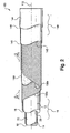
- Fig. 3 is a side elevational, cut-away view of a representative flexible thermoplastic tubing construction according to an embodiment of the invention.
- The drawings will be described further in connection with the following Detailed Description of the Invention.
- Certain terminology may be employed in the description to follow for convenience rather than for any limiting purpose. For example, the terms "forward," "rearward," "right," "left," "upper," and "lower" designate directions in the drawings to which reference is made, with the terms "inward," "interior," "inner," or "inboard" and "outward," "exterior," "outer," or "outboard" referring, respectively, to directions toward and away from the center of the referenced element, and the terms "radial" or "horizontal" and "axial" or "vertical" referring, respectively, to directions, axes, planes perpendicular and parallel to the central longitudinal axis of the referenced element. Terminology of similar import other than the words specifically mentioned above likewise is to be considered as being used for purposes of convenience rather than in any limiting sense.
- In the figures, elements having an alphanumeric designation may be referenced herein collectively or in the alternative, as will be apparent from context, by the numeric portion of the designation only. Further, the constituent parts of various elements in the figures may be designated with separate reference numerals which shall be understood to refer to that constituent part of the element and not the element as a whole. General references, along with references to spaces, surfaces, dimensions, and extents, may be designated with arrows.
- For the illustrative purposes of the discourse to follow, the precepts of the two or more layer tubular polymeric composite or laminate of the invention herein involved are described in connection with its utilization as a core tube or other member within a flexible pressure or vacuum hose construction such as for fuel transfer, oil or other natural resource recovery, chemical or pharmaceutical processing, or other applications requiring chemical or environmental resistance, or for use by itself as flexible tubing such as for airbrake applications. It will be appreciated, however, that aspects of the present invention may find use in other hose and tubing constructions in other fluid transfer applications, and in a variety of hydraulic or pneumatic power or control applications. Use within those such other applications therefore should be considered to be expressly within the scope of the present invention.
- Referring then to the figures wherein corresponding reference characters are used to designate corresponding elements throughout the several views with equivalent elements being referenced with prime or sequential alphanumeric designations, a representative two or more layer tubular polymeric composite member is shown generally in perspective cut-away at 10 in Fig. 1. In basic construction,
member 10 has an outer circumferential surface, 12, and an inner circumferential surface, 14, and is formed of as a laminate of a tubular first layer, 16, and a tubular second layer, 18, which is concentric with and integrally adjoins thefirst layer 16. Although the memberouter surface 12 is shown to be formed of thefirst layer 16, and the memberinner surface 14 is shown to be formed of thesecond layer 18, the relative orientation of the layers may be reversed as shown in Fig.3, in accordance with an embodiment of the invention, such that theouter surface 12 is formed of thesecond layer 18, and theinner surface 14 is formed of thefirst layer 16. Also, although the outer andinner surfaces member 10, it will be appreciated that in a multi-layer structure ofmember 10, one or more additional layers may be provided to surround the memberouter surface 12, and/or one or more additional layers may be provided to be surrounded by the memberinner surface 14. - The wall thicknesses of each of the
layers layers outer surface 12 and which forms theinner surface 14, thefirst layer 16 may be relatively thick as having a thickness, referenced at "t1", of between about 0.025-0.25 inch (0.63- 6.4 mm), withsecond layer 18 being relatively thin as having a thickness, referenced at "t2", of between about 0.001-0.1 inch (0.02-2.50 mm). For cost considerations, the wall thickness t2 of thesecond layer 18 may be maintained at the minimum necessary to provide the desired solvent, gas, or liquid permeation resistance, while for strength and flexibility considerations, the thickness t1 of thefirst layer 16 will be 1.25-75 times thicker than the thickness t2. Overall,member 10 may be of any diametric and lengthwise extent, and may be generally round in cross-section as shown, but alternatively may be of an elliptical, polygonal, or other geometric cross-section. - The
first layer 16 is formed of a first thermoplastic material, and thesecond layer 18 is formed of a second thermoplastic material different from the first material. In this regard, and as may be seen in cut-away in Fig. 3, the outer surface of thefirst layer 16 itself, and the inner surface of thesecond layer 18 itself, are directly bonded together, i.e., without the use of an intermediate tie-layer or adhesive, and also generally without preparation, priming, or other or treatment of surfaces so as to allow themember 10 to be formed by a continuous co-extrusion or other extrusion such as cross-head or sequential extrusion, in addition to molding or co-molding, or other processes such as coating, or a combination of extrusion, molding, and/or coating. With thelayers layers layers respective layers -
First layer 16 may be formed of any thermoplastic material, which may be filled or unfilled, but for reasons of cost typically will be a general purpose resin. As used herein, the term "thermoplastic material" is used interchangeably with "melt processible material," and is in contrast to non-melt processible materials such as thermosets or non-thermosetting materials which otherwise exhibit a melt viscosity that is sufficiently high so as to preclude flow and processing by conventional melt extrusion or molding operations, and therefore necessitating that the material be processed using sintering or solvent processing techniques. Such general purpose resin materials include polyamides, polyolefins, polyesters, polyvinyl chlorides, ethylene vinyl alcohols (EVA), polyacetals, polyoxymethylenes (POM), silicones, thermoplastic rubbers (TPR) such as polyolefin-ethylene-propylene-diene monomer (EPDM) and other blends, copolymer rubbers, thermoplastic polyurethanes (TPU) and other thermoplastic elastomers (TPE), and blends of any of the foregoing. Such resins typically will have a melting point of between about 110-230°C, and a thermal decomposition temperature, which defines the upper processing limit of the resin, of between about 150-260°C. As used herein, "melting point" may be a transition from a form-stable crystalline or glassy solid phase to a softened or otherwise viscous phase which may be generally characterized as exhibiting intermolecular chain rotation and, as between layers, chain diffusion and/or other intermingling. For amorphous or other thermoplastic resins not having a clearly defined melting peak, the term melting point also is used interchangeably with glass transition or softening point. - In many applications, a polyamide and, particularly, a plasticized or unplasticized nylon such as Nylon 6, 6/66, 11, 12, or 6/12, may be preferred. The specific nylon may be chosen for reasons of cost and/or for service temperature, chemical compatibility with the fluid being handled, fluid, solvent, moisture, or environmental resistance, flexural modulus, hardness, or other physical property, and typically will have a melting point of between about 175-235°C and a thermal decomposition temperature of between about 195-280°C.
-
Second layer 18 preferably is formed of fluoropolymer material which is more chemically-resistant, but typically higher in cost and less flexible, impact resistant, or otherwise less strong or tough than the resin material of thefirst layer 12. As used herein, "chemical resistance" should be understood to mean the ability to resist swelling, crazing, stress cracking, corrosion, or otherwise to withstand attack from mild acidic or alkaline solutions, phosphate-ester solutions, and alcohols and other organic solvents and hydrocarbons, as well as inorganic solvents such as water or brine. - The fluoropolymer material may be as is described in European Patent Publ. No. EP 992,518, and in that regard may be an ETFE-based fluoropolymer material that has been modified, i.e., an EFEP, to be melt processible, such as by co-extrusion or molding, to the nylon or other polyamide or other resin material of the
first layer 16. As mentioned, such fluoropolymer material may be formulated as a fluororesin copolymer having terminal functional groups, which may be carbonate end groups, which are reactive with the amide or other functional groups of the nylon or other resin material of thefirst layer 16. - The fluororesin copolymer may comprise, based on the copolymer, between about 30-81 mole % of a tetrafluoroethylene (TFE) monomer, and about 19-70 mole % of at least one other monomer. A preferred composition is a terpolymer of about 40-81 mole % TFE, 6-43 mole % ethylene, and 10-30 mole % of hexafluoropropylene (HFP), and in that regard may be characterized as a modified ethylene tetraflurorethylene (ETFE) copolymer or as an "EFEP" (ethylene-perfluoroethylene) copolymer. The composition also may contain 0-10 mole % of a fluorovinyl compound. The carbonate end groups, which may be incorporated into the copolymer chains by the use of a peroxycarbonate polymerization initiator, may be considered an activator in having a high reactivity with the polyamides bonds and/or terminal amino or carboxyl groups of materials such as polyamides.
- Advantageously, these modified fluoropolymer materials are able to be fusion bonded, such as by co-extrusion or molding, to a general purpose resin such as a nylon or other polyamide at a temperature below the thermal decomposition temperature of the resin, and preferably at a temperature within the range of between about 150-280°C or otherwise within the range of the preferred fusion bonding temperature of the resin. In this regard, the fluororesin copolymer may be formulated to have melting point, such as between about 90-200°C, and a melt viscosity, such as a melt flow rate of between about 0.1-100 g/10 minutes under a load of 5 kg, which allows flow of the copolymer within such fusion bonding temperature range of the resin. Modified ETFE, i.e., EFEP. fluoropolymer materials of the above-described type are sold commercially by Daikin America, Inc. (Orangeburg, NY) under the designations Neoflon™ RP-5000 and RP-5000AS Series. Such materials have a melting point of about 195°C, which is lower than the melting point of 220°C or higher for unmodified or conventionally modified ETFE materials.
- As depending upon the requirements of the particular application involved, one or both of the first and second thermoplastic materials of the
layers - Turning next to Fig. 2, a representative hose
construction incorporating member 10 is shown generally at 100 in the cut-away view of Fig. 2 as extending along a central longitudinal axis, 112. In thehose 100, thecomposite member 10 is provided as a core about which the remainder of the hose is constructed, and in that regard the memberinner surface 14 forms the innermost surface of the hose and defines the inner diameter thereof. - As is shown in Fig. 2, one or more reinforcement layers, 130a-b, may be provided as wound on directly or otherwise to surround the
outer surface 12 of themember 10. Each of the reinforcement layers 130 may be conventionally formed as braided, knitted, wrapped, or, as is shown, spiral, i.e., helically, wound of, for example, from 1 to about 60 ends of monofilament, continuous multi-filament, i.e., yarn, stranded, cord, roving, thread, tape, or ply, or short "staple" strands of a fiber material. The fiber material, which may be the same or different inlayers 130a-b, may be a natural or synthetic polymeric material such as a nylon, cotton, polyester, polyamide, aramid, polyolefin, polyvinyl alcohol (PVA), polyvinyl acetate, or polyphenylene bezobisoxazole (PBO), or blend, a steel, which may be stainless or galvanized, brass, zinc or zinc-plated, or other metal wire, or a blend thereof. - In the illustrated
spiral wound construction 100 of Fig. 2, which also may contain additional braided and/or knitted layers (not shown), the reinforcement layers 130 are oppositely wound in pairs so as to counterbalance torsional twisting effects. For each of the spiral woundlayers 130a-b, from 1 to about 60 parallel ends of, preferably, a 420-6600 denier (470-7400 decitex), multi-filament aramid, polyester, nylon, PVA, or PBO yarn may be helically wound under tension in one direction, i.e., either left or right hand, with the next immediately succeeding layer 130 being wound in the opposite direction. Thelayers 130a-b may be wound as is shown in Fig. 2 directly over theouter surface 12 ofmember 10, or, alternatively, over one or more intervening reinforcement or other layers, as having a predetermined pitched angle, referenced at θ in Fig. 2 forlayer 130a and at -0 forlayer 130b, measured relative to thelongitudinal axis 112 of thehose 100. - To better control the elongation and contraction of
hose 100, and for improved impulse fatigue life, theinnermost reinforcement layer 130a may be bonded, by means of fusion, mechanical, chemical, or adhesive bonding, or a combination thereof or otherwise, to the outer circumferentialouter surface 12 ofmember 10. Such bond may be effected by solvating, tackifying, or plasticizing thesurface 12 with an appropriate solvent, such as a carboxylic or other organic acid, tackifier, or plasticizer such as an aqueous or other solution of an amine such as n-methyl pyrrolidone or a phenol such as meta-cresol or resorcinol, or with the use of a urethane, epoxy, vinyl chloride, vinyl acetate, methyl acrylic, or other adhesive having an affinity to thematerials forming surface 12 andlayer 130a, or otherwise in the manner described, for example, in U.S. Patent. Nos. 3,654,967; 3,682,201; 3,773,089; 3,790,419; 3,861,973; 3,881,975; 3,905,398; 3,914,146; 3,982,982; 3,988,188; 4,007,070; 4,064,913; 4,343,333; 4,898,212; and in Japanese (Kokai) Publ. No. 10-169854 A2 and Canadian Patent No. 973,074. - The
outermost reinforcement layer 130b, in turn, may be sheathed within one or more layers of a coaxially-surrounding protective cover or jacket, referenced at 140, having a circumferential interior surface, 142, and an opposing circumferential exterior surface, 144. Depending upon its construction,cover 140 may be spray-applied, dip coated, cross-head or co-extruded, or otherwise conventionally extruded, spiral or longitudinally, i.e., "cigarette," wrapped, or braided over thereinforcement layer 130b as, for example, a 0.02-0.15 inch (0.5-3.8 mm) thick layer of an abrasion-resistant, preferably melt-processible, thermoplastic material, copolymer, alloy, or blend of a fiber, glass, ceramic, or metal-filled or unfilled polyamide, polyolefin, polyester, polyvinyl chloride, fluoropolymer, thermoplastic rubber (TPR), thermoplastic elastomer (TPE), thermoplastic olefm (TPO), or, most preferably, a thermoplastic polyurethane (TPU) elastomer. By "abrasion-resistant," it is meant that such thermoplastic material for formingcover 140 may have a hardness of between about 60-98 Shore A durometer. Cover 140 alternatively may be formed of a vulcanizable natural or synthetic rubber such as SBR, polybutadiene, EPDM, butyl, neoprene, nitrile, polyisoprene, silicone, fluorosilicone, buna-N, copolymer rubbers, or blends such as ethylene-propylene rubber. Any of thesematerials forming cover 140 may be loaded with metal particles, carbon black, or another electrically-conductive particulate, flake, or fiber filler so as to renderhose 100 electrically-conductive for static dissipation or other applications. Separate electrically-conductive fiber or resin layers (not shown), which may be in the form of spiral or "cigarette-wrapped" tapes or otherwise provided, also may be included in thehose construction 100 between themember 10 and theinnermost reinforcement layer 130a, between the reinforcement layers 130, or between theoutermost reinforcement layer 130b andcover 140. - Similar to the bonding of
member 10 to theinnermost reinforcement layer 130a, theinterior surface 142 ofcover 140 may be bonded to theoutermost reinforcement layer 130b. Such bond, again, may be by fusion, chemical, mechanical, or adhesive means, or a combination thereof or other means, and preferably will exhibit a strength of at least about 8 pli (1.43 kg/linear cm). As before, the bond may be effected by solvating, tackifying, or plasticizing the surface of theoutermost reinforcement layer 130b with an appropriate solvent, such as a carboxylic or other organic acid, tackifier, or plasticizer such as an aqueous or other solution of an amine such as n-methyl pyrrolidone or a phenol such as meta-cresol or resorcinol, or with the use of a urethane or other adhesive having an affinity to the materials formingreinforcement layer 130b and cover 140, or otherwise in the manner described in the above-cited references or in the manner to be described in connection with the bonding between layers 30a-b. - In the illustrative multi-layer construction of
cover 140 shown in Figs. 2, cover 140 is provided as having an innermost cover layer, 146, which is formed of a first, preferably, thermoplastic material and which defines theinterior cover surface 142, and a surrounding outermost cover layer, 148, which, is formed of a second, preferably, thermoplastic material and which defines theexterior cover surface 144. Depending upon the application, the relative thicknesses of thelayers hose 100, the first thermoplastic material forming theinnermost cover layer 146 may be selected as having a flexural modulus which is lower than the flexural modulus of theoutermost cover layer 148. In this way, the thickness of the less flexibleoutermost cover layer 148 may be decreased as compared to a single layer construction ofcover 140. Although many combinations of materials may be used, the first thermoplastic material forming the more flexibleinnermost layer 146 may be a polyamide, polyolefin, polyester, EVA, TPO, TPE, TPU, TPR, fluoroelastomer or other fluoropolymer, polyvinyl chloride, silicone, polyurethane, a natural or synthetic rubber, or a copolymer of blend thereof, with the second material being, independently, a less flexible but harder, i.e., at least about 60 Shore A durometer, filled or unfilled polyamide, polyurethane, polyester, polyolefin, fluoropolymer, TPE, ionomer resin such as "Surlyn®" (DuPont, Wilmington, DE), or a copolymer or blend thereof. If formed of chemically compatible thermoplastic materials, therespective layers respective layers - With continuing reference to Fig. 2, each of the reinforcement layers, such as
layer 130a, withinhose 100 may be bonded, typically chemically and also, in most instances, mechanically, to its immediately succeeding layer, such aslayer 130b, so as to provide for the more efficient transfer of induced internal or external stresses. By "chemically bonded," it is meant that the layers are bonded together, such as by fusion or cross-linking, directly or indirectly through an intermediate adhesive, resin, or other interlayer, as referenced at 160 in Fig. 2, or otherwise via a bonding agent, which may be a plasticizer, tackifier, solvent, or the like, such that atoms of the materials forming the reinforcement layers 130a-b are bonded to atoms of theother layer material forming interlayer 160. The chemical bond may be either covalent, ionic, or hydridic, i.e., hydrogen, bridge bonding, and may result, along with any mechanical bonding, in the formation of an integral reinforcement structure. Hose constructions of the type herein involved are described further in commonly-assigned, co-pending application U.S.S.N 10/040,809, filed January 8, 2002, and in the references cited therein. In a collapse-resistant construction, such as is described further in commonly-assigned, co-pending application U.S.S.N 09/466,375, filed December 17, 1999,reinforcement layers 130a-b alternatively may be provided as a spiral-wound metal or resin coil encapsulated between two elastomeric layers. - Although the
hose construction 100 of Fig. 2 is shown to employcomposite member 10 as a core,composite member 10 additionally or instead may be provided as surrounding the reinforcement layer 130 so as to provide, for example, protection against external moisture permeation, and/or as a substitute for thecover 140. Also, although theillustrative hose construction 100 has been described wherein two spiral wound reinforcement layers 130 are employed, other constructions may be envisioned. For example, and as was mentioned, one or more braided and/or knitted layers, which may be formed of natural, synthetic, or metal fiber, may be used in combination with, or instead of, the spiral wound layers 130 depending upon the specific requirements of the particular application involved. - Turning next to Fig. 3, a representative tubing construction, such as for airbrake applications, is shown generally at 150, as incorporating member 10' embodying the invention. Member 10' is constructed generally as was described in connection with
member 10 of Fig. 1, but as wherein the orientation of the first andsecond layers outer surface 12 of member 10' is formed of the fluoropolymer material of thesecond layer 18, which functions as a cover or jacket, while theinner surface 14 of member 10' is formed of the resin material of thefirst layer 16 which functions as a core. Further in this regard, theouter surface 12 of the member 10' may be seen to form the outermost surface of thetubing 150, with theinner surface 14 of the member 10' forming the innermost surface of thetubing 150. Accordingly, intubing 150 the fluoropolymer material of thelayer 18 may provide a protective barrier layer against external moisture and corrodants such as methanol and other solvents which may be used to clean the vehicle on which thetubing 150 is used.Tubing 150 may be linear and used in a harness or bundle or, and as is shown in phantom at 152, thermoformed or otherwise formed into helically-wound into a coil for use as a brake coil of the type described, for example, in commonly-assigned U.S. Pat. No. 6,098,666, and the references cited therein. Such coil may be both extendable and self-retracting. Representative airbrake and other coil tubing assemblies are shown in U.S. Patent Nos. 3,3,977,440; 4,009,734; and 5,232,645; and in U.K. Patent Application 2,239,503. - In a reinforced construction, the outer surface, 154, of the
first layer 16 itself may be surrounded by one or more layers of a relatively open braided, wound, or other reinforcement (not shown). Such reinforcement conventionally may be a nylon, polyester, or aramid filament or yarn. Also, the material of thesecond layer 18 may be filled with a pigment or otherwise may contain a dye or other colorant such as for color-coding thetubing 150. - Thus, two or more layer tubular polymeric composites, and articles such as hose and tubing constructed thereof, have been described. As it is anticipated that certain changes may be made in the present invention without departing from the precepts herein involved, it is intended that all matter contained in the foregoing description shall be interpreted as illustrative and not in a limiting sense.
Claims (14)
- An article having an innermost surface and an outermost surface, the article comprising a tubular polymeric composite member having a circumferential inner surface and a circumferential outer surface, said composite member comprising a tubular first layer and a tubular second layer concentric with and adjoining the first layer,
characterized in that:the first layer is formed of a first thermoplastic material having amide functional groups; andthe second layer is formed of a second thermoplastic material different from the first thermoplastic material, the second thermoplastic material having terminal carbonate functional groups reactive with the amide functional groups and being fusion bondable to the first thermoplastic material and comprising a fluoropolymer, and the second layer being fusion bonded directly to the first layer, wherein the outer surface of the composite member is formed by the second layer and forms the outermost surface of the article. - The article of claim 1 wherein the second thermoplastic material comprises a fluororesin copolymer.
- The article of claim 2 wherein the fluororesin copolymer comprises, based on the copolymer:between about 30-81 mole % tetrafluoroethylene; andbetween about 19-70 mole % of at least one other monomer.
- The article of claim 2 wherein the fluororesin copolymer comprises:between about 40-81 mole % tetrafluoroethylene;between about 6-43 mole % ethylene; andbetween about 10-30 mole % of hexafluoropropylene.
- The article of claim 4 wherein the fluororesin copolymer further comprises between about 0-10% of a fluorovinyl compound.
- The article of claim 2 wherein the second thermoplastic material has a melting point of between about 90-200°C and a melt flow rate of between about 0.1-100 g/10 minutes under a load of 5 kg.
- The article of claim 1 wherein the second thermoplastic material comprises the reaction product of a fluororesin copolymer and a peroxycarbonate initiator.
- The article of claim 7 wherein the fluororesin copolymer comprises tetrafluoroethylene.
- The article of claim 8 wherein the fluororesin copolymer further comprises ethylene.
- The article of claim 1 wherein the first thermoplastic material comprises a polyamide.
- The article of claim 1 wherein:the article further comprises a reinforcement layer surrounding the outer surface of the composite member, the reinforcement layer including one or more filaments of one or more fibers braided or wound to surround the outer surface of the composite.
- The article of claim 1 wherein the composite member is formed into a helical coil.
- The article of claim 1 wherein the first thermoplastic material has a thermal decomposition temperature of between about 150-260°C, and the second thermoplastic material is melt-processible at a temperature which is less than the thermal decomposition temperature of the first thermoplastic material.
- The article of claim 1 wherein:the article further comprises a tubular core having a circumferential outer surface, and a reinforcement layer surrounding the outer surface of the core, the reinforcement layer including one or more filaments of one or more fibers braided or wound to surround the outer surface of the core; andthe composite member has a circumferential inner surface surrounding the reinforcement layer.
Applications Claiming Priority (5)
| Application Number | Priority Date | Filing Date | Title |
|---|---|---|---|
| US27887101P | 2001-03-26 | 2001-03-26 | |
| US278871P | 2001-03-26 | ||
| US28311801P | 2001-04-11 | 2001-04-11 | |
| US283118P | 2001-04-11 | ||
| PCT/US2002/009689 WO2002076734A1 (en) | 2001-03-26 | 2002-03-26 | Tubular polymeric composites for tubing and hose constructions |
Publications (2)
| Publication Number | Publication Date |
|---|---|
| EP1383650A1 EP1383650A1 (en) | 2004-01-28 |
| EP1383650B1 true EP1383650B1 (en) | 2006-08-16 |
Family
ID=26959314
Family Applications (1)
| Application Number | Title | Priority Date | Filing Date |
|---|---|---|---|
| EP02753873A Revoked EP1383650B1 (en) | 2001-03-26 | 2002-03-26 | Tubular polymeric composites for tubing and hose constructions |
Country Status (11)
| Country | Link |
|---|---|
| US (1) | US6776195B2 (en) |
| EP (1) | EP1383650B1 (en) |
| KR (1) | KR100853905B1 (en) |
| AT (1) | ATE336370T1 (en) |
| AU (1) | AU2002306948B2 (en) |
| BR (1) | BR8203366U (en) |
| CA (1) | CA2441976C (en) |
| DE (1) | DE60213962T2 (en) |
| DK (1) | DK1383650T3 (en) |
| MX (1) | MXPA03008580A (en) |
| WO (1) | WO2002076734A1 (en) |
Cited By (2)
| Publication number | Priority date | Publication date | Assignee | Title |
|---|---|---|---|---|
| EP2103856A1 (en) | 2008-03-19 | 2009-09-23 | ContiTech Schlauch GmbH | Hose with an electrically conductive inner coating |
| EP2177348A1 (en) | 2008-10-15 | 2010-04-21 | ContiTech Schlauch GmbH | Tube with use in pharmaceutical and food sector |
Families Citing this family (67)
| Publication number | Priority date | Publication date | Assignee | Title |
|---|---|---|---|---|
| EP1270211A1 (en) * | 2001-06-19 | 2003-01-02 | Atofina | Structure comprising a fluoropolymer layer and a piperazine based bonding agent |
| FR2835306B1 (en) * | 2002-01-31 | 2004-05-21 | Nobel Plastiques | PIPE FOR TRANSPORTING AUTOMOTIVE FLUIDS, COMPRISING A SMOOTH INTERIOR TUBE AND AN OUTER RING TUBE |
| US20030186008A1 (en) * | 2002-03-29 | 2003-10-02 | Sutton Stephen P. | Spirally wound packages of soft thermoplastic elastomer tape, film, or sheet and processes for producing same |
| FR2845453B1 (en) * | 2002-10-07 | 2004-11-26 | Nobel Plastiques | PIPELINE FOR THE TRANSPORT OF HYDROGEN-CONTAINING FLUIDS |
| CN1809457B (en) * | 2003-06-17 | 2010-10-06 | 大金工业株式会社 | Laminated resin molded article, method for producing laminated resin molded article, and multilayer molded article |
| EP1658163B1 (en) | 2003-08-19 | 2020-01-01 | Solvay Specialty Polymers USA, LLC. | Impact-modified polyamide hollow body |
| JP4502309B2 (en) * | 2003-08-26 | 2010-07-14 | 株式会社潤工社 | Cylindrical member made of fluororesin |
| WO2005100843A2 (en) * | 2004-04-06 | 2005-10-27 | E.I. Dupont De Nemours And Company | Lined vessels for conveying chemicals |
| US20050287326A1 (en) * | 2004-06-29 | 2005-12-29 | Crane Resistoflex | Smooth inner bore hose with continuous fluoropolymer liner |
| US8413723B2 (en) * | 2006-01-12 | 2013-04-09 | Schlumberger Technology Corporation | Methods of using enhanced wellbore electrical cables |
| GB0505207D0 (en) * | 2005-03-14 | 2005-04-20 | Wellstream Int Ltd | Pipe fitting |
| US20070036926A1 (en) * | 2005-08-12 | 2007-02-15 | Fish Robert B Jr | Multilayered pipes |
| US7722819B2 (en) * | 2005-10-11 | 2010-05-25 | Meadwestvaco Calmar, Inc. | Fragrance product, dispenser, and dispenser assembly |
| US20070087150A1 (en) | 2005-10-19 | 2007-04-19 | Powell Steven M | Tubular Copolyester Member for Tubing and Hose Constructions |
| DE102005056286A1 (en) * | 2005-11-24 | 2007-05-31 | Degussa Gmbh | Producing a composite part from plastic parts that cannot be directly welded together comprises using an intermediate film with surfaces compatible with each part |
| US20080314470A1 (en) * | 2005-11-30 | 2008-12-25 | Parker Hannifin Corporation | High Temperature Thermoplastic Power Steering Hose |
| US20070181202A1 (en) * | 2006-02-03 | 2007-08-09 | Electrovations, Inc., A Corporation Of The State Of Ohio | Brake hose |
| EA012030B1 (en) * | 2006-02-27 | 2009-06-30 | Белл Хеликоптер Текстрон, Инк. | Fluid conduit with self-healing protective sleeve |
| WO2007101259A2 (en) * | 2006-02-28 | 2007-09-07 | Vici Metronics, Inc. | Dual-layer chemically-inert tubing and machine |
| JP4993188B2 (en) * | 2006-03-29 | 2012-08-08 | 国立大学法人東北大学 | Resin piping |
| WO2007120642A2 (en) * | 2006-04-11 | 2007-10-25 | Daikin Industries, Ltd. | Dual-containment pipe containing fluoropolymer |
| US20070248823A1 (en) * | 2006-04-24 | 2007-10-25 | Daikin Industries, Ltd. | Fluorine containing copolymer fiber and fabric |
| US8048351B2 (en) * | 2006-08-14 | 2011-11-01 | Swagelok Company | Bio-pharmaceutical hose |
| US20080053552A1 (en) * | 2006-09-01 | 2008-03-06 | Shope Jeffrey R | Wireless rubber vacuum hose |
| US8336679B2 (en) * | 2006-09-12 | 2012-12-25 | Honda Motor Co., Ltd. | Brake system and method |
| US20080145584A1 (en) * | 2006-12-15 | 2008-06-19 | Fish Robert B | Multilayered composite articles |
| EP1974903A1 (en) * | 2007-03-29 | 2008-10-01 | Tokai Rubber Industries, Ltd. | Low gas-permeable hose |
| US20090017244A1 (en) * | 2007-07-10 | 2009-01-15 | Nicola Martino | Nylon tubing constructions |
| WO2009020181A1 (en) * | 2007-08-08 | 2009-02-12 | Daikin Industries, Ltd. | Multilayer body composed of fluororesin layer and elastomer layer |
| US8936583B2 (en) | 2007-09-28 | 2015-01-20 | Hollister Incorporated | Multi-layer catheter tubes with odor barrier |
| DK2203208T3 (en) | 2007-09-28 | 2019-07-29 | Hollister Inc | MULTI-LOW SMALL BARRIER HOSE AND COMBINATION OF AIR BARRIER HOSE AND AIR BARRIER COLLECTION BAG |
| US20090151805A1 (en) * | 2007-12-13 | 2009-06-18 | Martino Nick A | Blow-out prevention hose bundle for offshore oil rigs |
| JP5305373B2 (en) * | 2007-12-28 | 2013-10-02 | 国立大学法人東北大学 | Resin piping |
| US8697992B2 (en) | 2008-02-01 | 2014-04-15 | Schlumberger Technology Corporation | Extended length cable assembly for a hydrocarbon well application |
| WO2009123929A2 (en) * | 2008-04-03 | 2009-10-08 | Rodney Ruskin | Low friction lining for drip irrigation conduits |
| ITVI20080188A1 (en) * | 2008-08-05 | 2010-02-06 | Fitt Spa | FLEXIBLE HOSE WITH METALLIC APPEARANCE. |
| CA2742672C (en) * | 2008-11-21 | 2017-06-27 | Parker-Hannifin Corporation | Low temperature, high pressure rubber hose |
| US8356637B2 (en) * | 2009-03-18 | 2013-01-22 | Eaton Corporation | Hydraulic supply hose including an integral tensile load member |
| US12163394B2 (en) | 2009-04-17 | 2024-12-10 | Schlumberger Technology Corporation | Reduced torque wireline cable |
| US11387014B2 (en) | 2009-04-17 | 2022-07-12 | Schlumberger Technology Corporation | Torque-balanced, gas-sealed wireline cables |
| US9412492B2 (en) | 2009-04-17 | 2016-08-09 | Schlumberger Technology Corporation | Torque-balanced, gas-sealed wireline cables |
| US20100282354A1 (en) * | 2009-05-05 | 2010-11-11 | Electrovations, Inc. | Brake hose |
| US8955552B2 (en) | 2009-07-24 | 2015-02-17 | Parker-Hannifin Corporation | Fire resistant hose assembly |
| CA2774775A1 (en) | 2009-09-22 | 2011-03-31 | Schlumberger Canada Limited | Wireline cable for use with downhole tractor assemblies |
| EP2347707B1 (en) * | 2010-01-22 | 2015-07-15 | Dräger Medical GmbH | Tube for a blood pressure cuff, blood pressure cuff and method |
| US20130011595A1 (en) | 2010-04-29 | 2013-01-10 | Parker-Hannifin Corporation | Nylon airbrake tubing constructions |
| US8713944B2 (en) | 2010-09-23 | 2014-05-06 | Delavan Inc. | High temperature manifolds for gas turbine engines |
| US10238776B2 (en) * | 2010-12-29 | 2019-03-26 | St. Jude Medical, Atrial Fibrillation Division, Inc. | Hydrophobic catheter and composition |
| CN202691565U (en) * | 2012-06-05 | 2013-01-23 | 张家港中集圣达因低温装备有限公司 | Glass steel tube and low temperature pressure vessel |
| EP2897800B1 (en) | 2012-09-24 | 2018-10-31 | Eaton Corporation | Air brake tubing and compositions for making the same |
| WO2014099116A1 (en) * | 2012-12-19 | 2014-06-26 | Utc Fire & Security Americas Corporation, Inc. | Flexible conduit for use in a fire suppression system |
| US9913933B2 (en) | 2013-03-15 | 2018-03-13 | St. Jude Medical, Cardiology Division, Inc. | Multilayered catheter shaft containing polyvinylidene fluoride polymers |
| KR20150046790A (en) * | 2013-09-24 | 2015-05-04 | 한일튜브 주식회사 | Hydrogen transfer tube |
| EP3069875B1 (en) * | 2015-03-17 | 2017-07-05 | Evonik Degussa GmbH | Multilayer compound with one fluoropolymer layer |
| ES2734306T3 (en) * | 2017-01-10 | 2019-12-05 | Thermoplastic composite tube with multi-layer intermediate layer | |
| EP3687784A4 (en) * | 2017-09-28 | 2021-06-30 | Saint-Gobain Performance Plastics Corporation | FUEL PIPES AND METHOD OF MANUFACTURING AND USING THEREOF |
| DE102018114583A1 (en) * | 2018-06-18 | 2019-12-19 | Nemos Gmbh | Arrangement for transmitting torsional moments, in particular as a torsion spring or drive shaft made of fiber composite materials in order to achieve a high specific material utilization |
| DE102018118460A1 (en) * | 2018-07-31 | 2020-02-06 | Shimano Inc. | HYDRAULIC DEVICE |
| JP2022533707A (en) | 2019-05-22 | 2022-07-25 | サン-ゴバン パフォーマンス プラスティックス コーポレイション | Multilayer flexible tube and manufacturing method thereof |
| GB2599553B (en) | 2019-06-28 | 2025-03-26 | Schlumberger Technology Bv | Stranded fiber-optic cable |
| US12104718B2 (en) | 2021-02-17 | 2024-10-01 | Gamra Composites, Inc. | Fiber reinforced hoses, composite materials and articles, and related methods |
| US12145329B2 (en) | 2021-02-17 | 2024-11-19 | Gamra Composites, Inc. | Fiber reinforced composite materials, articles and related methods |
| CN112963632A (en) * | 2021-03-11 | 2021-06-15 | 四川泰鑫实业发展有限责任公司 | Flexible composite pipe and production method and production device thereof |
| WO2022261390A1 (en) | 2021-06-10 | 2022-12-15 | Schlumberger Technology Corporation | Electro-optical wireline cables |
| KR102584204B1 (en) * | 2021-09-03 | 2023-10-05 | 주식회사 에스엠티 | Core insertion type spiral tube and making method for the same |
| US20240325707A1 (en) * | 2023-03-31 | 2024-10-03 | Carefusion 303, Inc. | Multilayer medical tubing with low sorbability |
| CN121273985B (en) * | 2025-12-08 | 2026-04-14 | 万华化学集团股份有限公司 | High-temperature-resistant polyamide composite reinforced pipe and preparation method thereof |
Family Cites Families (24)
| Publication number | Priority date | Publication date | Assignee | Title |
|---|---|---|---|---|
| US3722550A (en) | 1970-03-10 | 1973-03-27 | Moore & Co Samuel | Composite tubing and method for making the same |
| US3977440A (en) * | 1972-05-03 | 1976-08-31 | Samuel Moore And Company | Composite brake hose |
| US4009734A (en) * | 1976-02-26 | 1977-03-01 | Parker-Hannifin Corporation | Coiled tubing |
| US4603712A (en) | 1985-03-29 | 1986-08-05 | The Gates Rubber Company | Compounded polychloroprene formulation used as an adhesive layer in the manufacture of elastomeric articles |
| DE4112668A1 (en) | 1991-04-18 | 1992-10-22 | Huels Chemische Werke Ag | THERMOPLASTIC MULTILAYER COMPOSITION |
| US5232645A (en) * | 1992-01-03 | 1993-08-03 | Ramos Jr Phillip M | Process for making coiled brake tubing |
| WO1993014933A1 (en) * | 1992-01-30 | 1993-08-05 | E.I. Du Pont De Nemours And Company | Laminar structure of polyimide and low melting fluoropolymer |
| JP2578705B2 (en) * | 1992-03-30 | 1997-02-05 | 東海ゴム工業株式会社 | Resin tube for fuel pipe and method of manufacturing the same |
| DE4215608A1 (en) | 1992-05-12 | 1993-11-18 | Huels Chemische Werke Ag | Multi-layer plastic pipe |
| US6634389B2 (en) * | 1992-06-11 | 2003-10-21 | Itt Industries, Inc. | Multi-layer fuel and vapor tube |
| FR2700292B1 (en) * | 1993-01-13 | 1995-02-24 | Atochem Elf Sa | Composite tubular article formed from a vulcanized elastomer associated with a thermoplastic elastomer having polyamide sequences, in particular gasoline pipe and process for preparing such an article. |
| EP0637509B1 (en) * | 1993-08-03 | 2002-10-23 | Nitta Moore Company | A tube for fuel transportation |
| DE69430050D1 (en) | 1993-09-10 | 2002-04-11 | Tokai Rubber Ind Ltd | FUEL HOSE METHOD AND DEVICE FOR PRODUCING IT |
| DE4336289A1 (en) | 1993-10-25 | 1995-04-27 | Huels Chemische Werke Ag | Multi-layer plastic tube |
| DE4410148A1 (en) | 1994-03-24 | 1995-09-28 | Huels Chemische Werke Ag | Multi-layer plastic tube |
| DE69826007T2 (en) * | 1997-06-23 | 2005-09-15 | Daikin Industries, Ltd. | TETRAFLUORETHYLENE COPOLYMER AND ITS USE |
| US6071579A (en) | 1998-02-11 | 2000-06-06 | Furon | Laminated air brake tubing |
| US6066377A (en) | 1998-08-17 | 2000-05-23 | Furon | Laminated air brake tubing |
| FR2785965B1 (en) * | 1998-11-17 | 2001-01-19 | Tricoflex Sa | MULTILAYER HOSE FOR THE TRANSPORT OF HIGHLY SOLVENT CHEMICALS |
| US6098666A (en) | 1999-01-13 | 2000-08-08 | Parker-Hannifin Corporation | Dual coil tubing assembly |
| FR2791116B1 (en) * | 1999-03-16 | 2001-04-27 | Atochem Elf Sa | POLYAMIDE-BASED ANTISTATIC TUBE FOR FUEL TRANSPORT |
| EP1217279B2 (en) * | 1999-09-30 | 2012-11-14 | Asahi Glass Company, Limited | Fuel hose |
| WO2001081077A1 (en) * | 2000-04-24 | 2001-11-01 | Asahi Glass Company, Limited | Hose for fuel |
| JP2003287165A (en) * | 2002-01-24 | 2003-10-10 | Tokai Rubber Ind Ltd | Hose for fuel |
-
2002
- 2002-03-26 US US10/108,715 patent/US6776195B2/en not_active Expired - Lifetime
- 2002-03-26 AT AT02753873T patent/ATE336370T1/en not_active IP Right Cessation
- 2002-03-26 BR BR8203366-8U patent/BR8203366U/en not_active Application Discontinuation
- 2002-03-26 KR KR1020037012473A patent/KR100853905B1/en not_active Expired - Fee Related
- 2002-03-26 DE DE60213962T patent/DE60213962T2/en not_active Expired - Lifetime
- 2002-03-26 AU AU2002306948A patent/AU2002306948B2/en not_active Ceased
- 2002-03-26 MX MXPA03008580A patent/MXPA03008580A/en active IP Right Grant
- 2002-03-26 CA CA002441976A patent/CA2441976C/en not_active Expired - Lifetime
- 2002-03-26 EP EP02753873A patent/EP1383650B1/en not_active Revoked
- 2002-03-26 DK DK02753873T patent/DK1383650T3/en active
- 2002-03-26 WO PCT/US2002/009689 patent/WO2002076734A1/en not_active Ceased
Cited By (5)
| Publication number | Priority date | Publication date | Assignee | Title |
|---|---|---|---|---|
| EP2103856A1 (en) | 2008-03-19 | 2009-09-23 | ContiTech Schlauch GmbH | Hose with an electrically conductive inner coating |
| DE102008014988A1 (en) | 2008-03-19 | 2009-09-24 | Contitech Schlauch Gmbh | Hose with an electrically conductive inner layer |
| EP2177348A1 (en) | 2008-10-15 | 2010-04-21 | ContiTech Schlauch GmbH | Tube with use in pharmaceutical and food sector |
| DE102008037452A1 (en) | 2008-10-15 | 2010-04-22 | Contitech Schlauch Gmbh | Hose with application in the pharmaceutical and food industry |
| DE102008037452B4 (en) | 2008-10-15 | 2018-12-06 | Contitech Schlauch Gmbh | Pharmaceutical and food tube |
Also Published As
| Publication number | Publication date |
|---|---|
| KR100853905B1 (en) | 2008-08-25 |
| US20020134451A1 (en) | 2002-09-26 |
| KR20030085057A (en) | 2003-11-01 |
| BR8203366U (en) | 2004-03-02 |
| WO2002076734A1 (en) | 2002-10-03 |
| CA2441976C (en) | 2010-01-19 |
| MXPA03008580A (en) | 2003-12-08 |
| AU2002306948B2 (en) | 2007-03-01 |
| DE60213962T2 (en) | 2007-08-30 |
| DE60213962D1 (en) | 2006-09-28 |
| EP1383650A1 (en) | 2004-01-28 |
| US6776195B2 (en) | 2004-08-17 |
| DK1383650T3 (en) | 2006-12-27 |
| ATE336370T1 (en) | 2006-09-15 |
| CA2441976A1 (en) | 2002-10-03 |
Similar Documents
| Publication | Publication Date | Title |
|---|---|---|
| AU2002306948B2 (en) | Tubular polymeric composites for tubing and hose constructions | |
| AU2002306948A1 (en) | Tubular polymeric composites for tubing and hose constructions | |
| US8394471B2 (en) | Electrically-conductive hose | |
| AU2002243482B2 (en) | Thermoplastic reinforced hose construction and method of making the same | |
| EP1565681B1 (en) | Tubular polymeric composites for tubing and hose constructions | |
| EP1834126B1 (en) | Fire resistant hose construction | |
| EP3609696B1 (en) | High pressure compact spiral hydraulic hose | |
| AU2002243482A1 (en) | Thermoplastic reinforced hose construction and method of making the same | |
| EP2411718B1 (en) | Compact high pressure rubber hose | |
| US20190186656A1 (en) | Spiral Hydraulic Hose | |
| US20090151805A1 (en) | Blow-out prevention hose bundle for offshore oil rigs | |
| CA2742672C (en) | Low temperature, high pressure rubber hose | |
| WO2017207306A1 (en) | Light weight, high performance tubed fuel line | |
| US20070087150A1 (en) | Tubular Copolyester Member for Tubing and Hose Constructions | |
| US20060280889A1 (en) | Tubular nylon alloy members for tubing and hose constructions |
Legal Events
| Date | Code | Title | Description |
|---|---|---|---|
| PUAI | Public reference made under article 153(3) epc to a published international application that has entered the european phase |
Free format text: ORIGINAL CODE: 0009012 |
|
| 17P | Request for examination filed |
Effective date: 20030923 |
|
| AK | Designated contracting states |
Kind code of ref document: A1 Designated state(s): AT BE CH CY DE DK ES FI FR GB GR IE IT LI LU MC NL PT SE TR |
|
| AX | Request for extension of the european patent |
Extension state: AL LT LV MK RO SI |
|
| 17Q | First examination report despatched |
Effective date: 20040706 |
|
| TPAC | Observations filed by third parties |
Free format text: ORIGINAL CODE: EPIDOSNTIPA |
|
| GRAP | Despatch of communication of intention to grant a patent |
Free format text: ORIGINAL CODE: EPIDOSNIGR1 |
|
| GRAS | Grant fee paid |
Free format text: ORIGINAL CODE: EPIDOSNIGR3 |
|
| GRAA | (expected) grant |
Free format text: ORIGINAL CODE: 0009210 |
|
| AK | Designated contracting states |
Kind code of ref document: B1 Designated state(s): AT BE CH CY DE DK ES FI FR GB GR IE IT LI LU MC NL PT SE TR |
|
| PG25 | Lapsed in a contracting state [announced via postgrant information from national office to epo] |
Ref country code: LI Free format text: LAPSE BECAUSE OF FAILURE TO SUBMIT A TRANSLATION OF THE DESCRIPTION OR TO PAY THE FEE WITHIN THE PRESCRIBED TIME-LIMIT Effective date: 20060816 Ref country code: IT Free format text: LAPSE BECAUSE OF FAILURE TO SUBMIT A TRANSLATION OF THE DESCRIPTION OR TO PAY THE FEE WITHIN THE PRESCRIBED TIME-LIMIT;WARNING: LAPSES OF ITALIAN PATENTS WITH EFFECTIVE DATE BEFORE 2007 MAY HAVE OCCURRED AT ANY TIME BEFORE 2007. THE CORRECT EFFECTIVE DATE MAY BE DIFFERENT FROM THE ONE RECORDED. Effective date: 20060816 Ref country code: CH Free format text: LAPSE BECAUSE OF FAILURE TO SUBMIT A TRANSLATION OF THE DESCRIPTION OR TO PAY THE FEE WITHIN THE PRESCRIBED TIME-LIMIT Effective date: 20060816 Ref country code: FI Free format text: LAPSE BECAUSE OF FAILURE TO SUBMIT A TRANSLATION OF THE DESCRIPTION OR TO PAY THE FEE WITHIN THE PRESCRIBED TIME-LIMIT Effective date: 20060816 Ref country code: BE Free format text: LAPSE BECAUSE OF FAILURE TO SUBMIT A TRANSLATION OF THE DESCRIPTION OR TO PAY THE FEE WITHIN THE PRESCRIBED TIME-LIMIT Effective date: 20060816 Ref country code: AT Free format text: LAPSE BECAUSE OF FAILURE TO SUBMIT A TRANSLATION OF THE DESCRIPTION OR TO PAY THE FEE WITHIN THE PRESCRIBED TIME-LIMIT Effective date: 20060816 |
|
| REG | Reference to a national code |
Ref country code: GB Ref legal event code: FG4D |
|
| REG | Reference to a national code |
Ref country code: CH Ref legal event code: EP |
|
| REG | Reference to a national code |
Ref country code: IE Ref legal event code: FG4D |
|
| REF | Corresponds to: |
Ref document number: 60213962 Country of ref document: DE Date of ref document: 20060928 Kind code of ref document: P |
|
| REG | Reference to a national code |
Ref country code: SE Ref legal event code: TRGR |
|
| PG25 | Lapsed in a contracting state [announced via postgrant information from national office to epo] |
Ref country code: ES Free format text: LAPSE BECAUSE OF FAILURE TO SUBMIT A TRANSLATION OF THE DESCRIPTION OR TO PAY THE FEE WITHIN THE PRESCRIBED TIME-LIMIT Effective date: 20061127 |
|
| REG | Reference to a national code |
Ref country code: DK Ref legal event code: T3 |
|
| PG25 | Lapsed in a contracting state [announced via postgrant information from national office to epo] |
Ref country code: PT Free format text: LAPSE BECAUSE OF FAILURE TO SUBMIT A TRANSLATION OF THE DESCRIPTION OR TO PAY THE FEE WITHIN THE PRESCRIBED TIME-LIMIT Effective date: 20070116 |
|
| REG | Reference to a national code |
Ref country code: CH Ref legal event code: PL |
|
| ET | Fr: translation filed | ||
| PLBI | Opposition filed |
Free format text: ORIGINAL CODE: 0009260 |
|
| PLAX | Notice of opposition and request to file observation + time limit sent |
Free format text: ORIGINAL CODE: EPIDOSNOBS2 |
|
| 26 | Opposition filed |
Opponent name: DEGUSSA GMBH Effective date: 20070515 |
|
| NLR1 | Nl: opposition has been filed with the epo |
Opponent name: DEGUSSA GMBH |
|
| PLAF | Information modified related to communication of a notice of opposition and request to file observations + time limit |
Free format text: ORIGINAL CODE: EPIDOSCOBS2 |
|
| PLAB | Opposition data, opponent's data or that of the opponent's representative modified |
Free format text: ORIGINAL CODE: 0009299OPPO |
|
| R26 | Opposition filed (corrected) |
Opponent name: EVONIK DEGUSSA GMBH Effective date: 20070515 |
|
| PLAF | Information modified related to communication of a notice of opposition and request to file observations + time limit |
Free format text: ORIGINAL CODE: EPIDOSCOBS2 |
|
| NLR1 | Nl: opposition has been filed with the epo |
Opponent name: EVONIK DEGUSSA GMBH |
|
| PG25 | Lapsed in a contracting state [announced via postgrant information from national office to epo] |
Ref country code: MC Free format text: LAPSE BECAUSE OF NON-PAYMENT OF DUE FEES Effective date: 20070331 |
|
| PLAF | Information modified related to communication of a notice of opposition and request to file observations + time limit |
Free format text: ORIGINAL CODE: EPIDOSCOBS2 |
|
| PLBB | Reply of patent proprietor to notice(s) of opposition received |
Free format text: ORIGINAL CODE: EPIDOSNOBS3 |
|
| PG25 | Lapsed in a contracting state [announced via postgrant information from national office to epo] |
Ref country code: GR Free format text: LAPSE BECAUSE OF FAILURE TO SUBMIT A TRANSLATION OF THE DESCRIPTION OR TO PAY THE FEE WITHIN THE PRESCRIBED TIME-LIMIT Effective date: 20061117 |
|
| PG25 | Lapsed in a contracting state [announced via postgrant information from national office to epo] |
Ref country code: LU Free format text: LAPSE BECAUSE OF NON-PAYMENT OF DUE FEES Effective date: 20070326 Ref country code: CY Free format text: LAPSE BECAUSE OF FAILURE TO SUBMIT A TRANSLATION OF THE DESCRIPTION OR TO PAY THE FEE WITHIN THE PRESCRIBED TIME-LIMIT Effective date: 20060816 |
|
| PG25 | Lapsed in a contracting state [announced via postgrant information from national office to epo] |
Ref country code: TR Free format text: LAPSE BECAUSE OF FAILURE TO SUBMIT A TRANSLATION OF THE DESCRIPTION OR TO PAY THE FEE WITHIN THE PRESCRIBED TIME-LIMIT Effective date: 20060816 |
|
| PLAB | Opposition data, opponent's data or that of the opponent's representative modified |
Free format text: ORIGINAL CODE: 0009299OPPO |
|
| R26 | Opposition filed (corrected) |
Opponent name: EVONIK DEGUSSA GMBH Effective date: 20070515 |
|
| NLR1 | Nl: opposition has been filed with the epo |
Opponent name: EVONIK DEGUSSA GMBH |
|
| PLAB | Opposition data, opponent's data or that of the opponent's representative modified |
Free format text: ORIGINAL CODE: 0009299OPPO |
|
| R26 | Opposition filed (corrected) |
Opponent name: EVONIK CARBON BLACK GMBH Effective date: 20070515 |
|
| PGFP | Annual fee paid to national office [announced via postgrant information from national office to epo] |
Ref country code: DK Payment date: 20110315 Year of fee payment: 10 Ref country code: IE Payment date: 20110328 Year of fee payment: 10 |
|
| PGFP | Annual fee paid to national office [announced via postgrant information from national office to epo] |
Ref country code: NL Payment date: 20110316 Year of fee payment: 10 Ref country code: SE Payment date: 20110314 Year of fee payment: 10 Ref country code: FR Payment date: 20110404 Year of fee payment: 10 |
|
| PGFP | Annual fee paid to national office [announced via postgrant information from national office to epo] |
Ref country code: DE Payment date: 20110325 Year of fee payment: 10 Ref country code: GB Payment date: 20110321 Year of fee payment: 10 |
|
| PLAB | Opposition data, opponent's data or that of the opponent's representative modified |
Free format text: ORIGINAL CODE: 0009299OPPO |
|
| R26 | Opposition filed (corrected) |
Opponent name: EVONIK DEGUSSA GMBH Effective date: 20070515 |
|
| RDAF | Communication despatched that patent is revoked |
Free format text: ORIGINAL CODE: EPIDOSNREV1 |
|
| PGFP | Annual fee paid to national office [announced via postgrant information from national office to epo] |
Ref country code: IT Payment date: 20110329 Year of fee payment: 10 |
|
| REG | Reference to a national code |
Ref country code: DE Ref legal event code: R064 Ref document number: 60213962 Country of ref document: DE Ref country code: DE Ref legal event code: R103 Ref document number: 60213962 Country of ref document: DE |
|
| PLAB | Opposition data, opponent's data or that of the opponent's representative modified |
Free format text: ORIGINAL CODE: 0009299OPPO |
|
| RDAG | Patent revoked |
Free format text: ORIGINAL CODE: 0009271 |
|
| STAA | Information on the status of an ep patent application or granted ep patent |
Free format text: STATUS: PATENT REVOKED |
|
| 27W | Patent revoked |
Effective date: 20111007 |
|
| GBPR | Gb: patent revoked under art. 102 of the ep convention designating the uk as contracting state |
Effective date: 20111007 |
|
| R26 | Opposition filed (corrected) |
Opponent name: EVONIK DEGUSSA GMBH Effective date: 20070515 |
|
| REG | Reference to a national code |
Ref country code: DE Ref legal event code: R107 Ref document number: 60213962 Country of ref document: DE Effective date: 20120405 |
|
| REG | Reference to a national code |
Ref country code: SE Ref legal event code: ECNC |