EP1384546A2 - Method of controlling a power supply for short circuit arc welding - Google Patents
Method of controlling a power supply for short circuit arc welding Download PDFInfo
- Publication number
- EP1384546A2 EP1384546A2 EP03254551A EP03254551A EP1384546A2 EP 1384546 A2 EP1384546 A2 EP 1384546A2 EP 03254551 A EP03254551 A EP 03254551A EP 03254551 A EP03254551 A EP 03254551A EP 1384546 A2 EP1384546 A2 EP 1384546A2
- Authority
- EP
- European Patent Office
- Prior art keywords
- wire
- short circuit
- arc
- current
- state
- Prior art date
- Legal status (The legal status is an assumption and is not a legal conclusion. Google has not performed a legal analysis and makes no representation as to the accuracy of the status listed.)
- Granted
Links
Images

Classifications
-
- B—PERFORMING OPERATIONS; TRANSPORTING
- B23—MACHINE TOOLS; METAL-WORKING NOT OTHERWISE PROVIDED FOR
- B23K—SOLDERING OR UNSOLDERING; WELDING; CLADDING OR PLATING BY SOLDERING OR WELDING; CUTTING BY APPLYING HEAT LOCALLY, e.g. FLAME CUTTING; WORKING BY LASER BEAM
- B23K9/00—Arc welding or cutting
- B23K9/09—Arrangements or circuits for arc welding with pulsed current or voltage
- B23K9/091—Arrangements or circuits for arc welding with pulsed current or voltage characterised by the circuits
- B23K9/092—Arrangements or circuits for arc welding with pulsed current or voltage characterised by the circuits characterised by the shape of the pulses produced
-
- B—PERFORMING OPERATIONS; TRANSPORTING
- B23—MACHINE TOOLS; METAL-WORKING NOT OTHERWISE PROVIDED FOR
- B23K—SOLDERING OR UNSOLDERING; WELDING; CLADDING OR PLATING BY SOLDERING OR WELDING; CUTTING BY APPLYING HEAT LOCALLY, e.g. FLAME CUTTING; WORKING BY LASER BEAM
- B23K9/00—Arc welding or cutting
- B23K9/09—Arrangements or circuits for arc welding with pulsed current or voltage
- B23K9/091—Arrangements or circuits for arc welding with pulsed current or voltage characterised by the circuits
-
- B—PERFORMING OPERATIONS; TRANSPORTING
- B23—MACHINE TOOLS; METAL-WORKING NOT OTHERWISE PROVIDED FOR
- B23K—SOLDERING OR UNSOLDERING; WELDING; CLADDING OR PLATING BY SOLDERING OR WELDING; CUTTING BY APPLYING HEAT LOCALLY, e.g. FLAME CUTTING; WORKING BY LASER BEAM
- B23K9/00—Arc welding or cutting
- B23K9/12—Automatic feeding or moving of electrodes or work for spot or seam welding or cutting
- B23K9/124—Circuits or methods for feeding welding wire
-
- B—PERFORMING OPERATIONS; TRANSPORTING
- B23—MACHINE TOOLS; METAL-WORKING NOT OTHERWISE PROVIDED FOR
- B23K—SOLDERING OR UNSOLDERING; WELDING; CLADDING OR PLATING BY SOLDERING OR WELDING; CUTTING BY APPLYING HEAT LOCALLY, e.g. FLAME CUTTING; WORKING BY LASER BEAM
- B23K9/00—Arc welding or cutting
- B23K9/12—Automatic feeding or moving of electrodes or work for spot or seam welding or cutting
- B23K9/124—Circuits or methods for feeding welding wire
- B23K9/125—Feeding of electrodes
-
- B—PERFORMING OPERATIONS; TRANSPORTING
- B23—MACHINE TOOLS; METAL-WORKING NOT OTHERWISE PROVIDED FOR
- B23K—SOLDERING OR UNSOLDERING; WELDING; CLADDING OR PLATING BY SOLDERING OR WELDING; CUTTING BY APPLYING HEAT LOCALLY, e.g. FLAME CUTTING; WORKING BY LASER BEAM
- B23K9/00—Arc welding or cutting
- B23K9/24—Features related to electrodes
- B23K9/28—Supporting devices for electrodes
- B23K9/29—Supporting devices adapted for making use of shielding means
- B23K9/291—Supporting devices adapted for making use of shielding means the shielding means being a gas
- B23K9/295—Supporting devices adapted for making use of shielding means the shielding means being a gas using consumable wire electrodes
-
- B—PERFORMING OPERATIONS; TRANSPORTING
- B23—MACHINE TOOLS; METAL-WORKING NOT OTHERWISE PROVIDED FOR
- B23K—SOLDERING OR UNSOLDERING; WELDING; CLADDING OR PLATING BY SOLDERING OR WELDING; CUTTING BY APPLYING HEAT LOCALLY, e.g. FLAME CUTTING; WORKING BY LASER BEAM
- B23K9/00—Arc welding or cutting
- B23K9/24—Features related to electrodes
- B23K9/28—Supporting devices for electrodes
- B23K9/30—Vibrating holders for electrodes
Definitions
- the present invention relates generally to the art of welding. More specifically, it relates to welding using a short circuit process.
- MIG welding is a widely used process that gives high heat input into the wire electrode and the workpiece, and thus can give high deposition rates.
- the process can be unstable and control of the arc length can be difficult.
- the MIG process is often performed as a short circuit welding.
- Short circuit welding is often performed as a MIG process.
- short circuit welding includes a short circuit state, wherein the welding wire is touching the weld pool thus creating a short circuit, and an arc state, wherein an arc is formed between the welding wire and the weld pool.
- the wire melts, and during the short circuit state the molten metal is transferred from the end of the wire to the weld puddle.
- Disadvantages of short circuit welding relate to the transitions between states, and instability of the process. Transition from the short circuit state to the arc state was typically caused by providing sufficient current to "pinch" off a droplet. The pinching off at high current can result in a violent disintegration of the molten metal bridge producing excessive weld spatter. Instability also results from the weld pool being pushed away.
- the present inventors have published descriptions of a controlled short circuit welding process where mechanical movement of the wire (advancing and retracting) is used to control the transition between welding states.
- the short circuit state is entered by advancing the wire until the wire touches the weld pool.
- the arc state is entered by retracting the wire until the wire does not touch the weld pool, and an arc forms.
- This system allows a typical output control to be used to control the energy delivered to the weld. By separating control of the transitions from control of energy, the system allows for better control of each.
- a controlled short circuit welding system requires the capability of advancing and retracting the wire.
- the inventors have disclosed in the literature the use of a stepper motor to control the wire movement.
- a stepper motor adequately provides for short term advancing and retracting of the wire.
- a stepper motor does not necessarily provide adequate feeding of the wire over the long term. Accordingly, a system that provides for advancing and retracting of the wire, and long term feeding of the wire, is desirable.
- controlled short circuit welding Another problem with controlled short circuit welding is that the prior art has not fully taken advantage of the process control made possible by the mechanical control of the state transitions. Thus, a controlled short circuit welder that provides for electrical control of the arc for the purpose of controlling heat into the weld, and not for causing transitions from one state to another, is desirable.
- the prior art has not adequately addressed the needs of short circuit welding at lower currents with thicker wires.
- the difficult to implement control schemes in particular, make it difficult to weld with thicker wire, such as 2.4 mm diameter wire, e.g., at low currents, such as less than 100 amps. Accordingly, a controlled short circuit welding process that may be used at low currents relative to the wire diameter is desirable.
- a method and apparatus for controlling a welding-type power supply includes providing a current wave form having an arc current portion and a short circuit current portion.
- An arc state is entered by retracting a welding wire, and a short circuit state is entered by advancing the wire.
- the current enters the arc current portion prior to the creation of the arc and the current enters the short circuit current portion prior to the creation of the short, by coordinating the wave form with the wire retraction.
- a welding process includes directing a wire having a diameter of 2.4 mm or more to a weld and applying a welding current of less than 100 amps, or of less than 35 amps.
- a method of controlled short circuit welding includes providing an arc state and a short circuit state.
- the current waveform during the arc state includes at least three segments, and the last segment is entered into prior to the short circuit state being entered, and is the same current magnitude as the current magnitude at the start of the short circuit state.
- Penetration and/or bead formation may be controlled by controlling the advancement of the wire into the weld pool in various embodiments.
- the current magnitude during the arc portion and/or the short portion is used to control heat applied to the weld, while advancing and retracting the wire is used to control the time at which the process transitions from one state to another in another alternative.
- the portion of time the process spends in the arc state relative to the short circuit state, or the arc/short balance, is controlled by controlling the length of time between the successive retraction and advancing of the wire in yet another embodiment. It may be controlled in response to a user selectable input indicatively of a desired arc state time, relative to a short circuit state time. Additionally, the process may include a pulse state, and the relative time in the pulse state may be controlled in response to a user selectable input. The process may include mixing, in various proportions, gas from two or more sources, and this may be performed in response to the users selectable input.
- Penetration is controlled by controlling the polarity of the current in one embodiment.
- the EP/EN balance may be controlled in response to a user selectable input.
- the present invention is a method and apparatus for controlled short circuit welding that includes mechanical control of transitions between the arc and short circuit states.
- the process includes a pulse mode. Control of energy to the weld is effected using the output current or voltage magnitude, wave shape, time, etc.
- the transitions are caused to occur, and current can be coordinated with, the transitions to reduce spatter, instability, or other undesirable features, by, for example, changing the current as the transition occurs, or in anticipation of the transition.
- Process cycle includes one cycle of the states of the process such as an arc state followed by a short circuit state, or an arc state, followed by a short circuit state, followed by a pulse state, etc.
- the advancing and retracting are, in the preferred embodiment, accomplished using a pair of motors disposed on either side of the wire, opposite one another and near (or mounted on) the torch.
- the motors are, in various embodiments stepper motors, servo motors, planetary drive motors, zero backlash motors, goalless motors, or replaced with a linear actuator.
- the pair is disposed one after the other in -one embodiment.
- Stepper motors are used in the preferred embodiment, and the number, and angle or size of the step is controlled to control the length of wire advanced or retracted.
- the preferred embodiment includes a wire feed motor mounted near the source of wire, such as a reel of wire, that drives the wire to the torch (although other embodiments omit this motor) .
- a buffer is provided to account for the increase in wire between the wire feed motor and the reversible motors.
- the reversible motors advance the wire, wire is withdrawn from the buffer.
- the reversible motors move the end of the wire in addition to the movement from the wire feed motor, or they superimpose motion onto motion imposed by the wire feed motor.
- the speed of the wire feed motor is slaved to the average speed of the reversible motors, so that, on average, they both drive the same length of wire, in the preferred embodiment.
- the buffer may be anything that stores and returns the extra wire, or provides an increased wire path, length between the source and the torch.
- the buffer of the preferred embodiment includes a wire liner about the wire for at least a portion of the distance from the source to the torch.
- the liner is disposed in a tube that is wider, and the liner can bend and flex within the tube, thus increasing the length of wire in a given length of tube.
- the tube is mounted to a hollow shaft, and the wire passes through the shaft.
- the shaft is fixed in one position. Thus, as the wire is retracted, the wire moves relative to the tube and shaft (or the tube and shaft may be said to move relative to the wire) .
- the shaft could be mounted to slide along the axis of the wire, and thus move relative to the tip of the torch, thereby increasing the length of the wire path between the tip (arc end) of the torch and the wire source end of the torch.
- the liner may be mounted to the shaft, and the wire moves relative to the liner.
- the liner is compressible, such as a coil spring, so that as the wire retracts, the spring compresses, in the preferred embodiment.
- Sensors may be provided that sense the amount of wire in the buffer, or the tension of the wire, and the process controlled (average wire feed speed e.g.) may be controlled in response thereto.
- a controller causes the motors to reverse at least once per process cycle in the preferred embodiment, and controls the current output based on mean arc current (average current during the arc state only, or a function thereof) , power, energy, voltage, or other welding output parameters.
- Feedback may include one or more of short detection, buffer feedback, tension feedback, pool oscillation, in addition to traditional welding parameters.
- Alternatives include reversing less frequently than once per cycle.
- One alternative provides for repeated reversals during the weld (i.e., not merely at the conclusion of the weld), but not once per cycle.
- the braking at the end of the arc cycle can feed forces between wire and droplet, which may disrupt the liquid bridge without retracting action. This is particularly present with lower wire diameters and higher short circuiting frequencies.
- the droplet has the speed of the wire before braking. This kinetic energy can be enough for disrupting the liquid path. In this case, no retracting is needed.
- the control may include controlling heat, penetration and/or bead formation by controlling the advancement of the wire into the weld pool.
- the relative time in arc state and short state (arc balance) may be set by the user (as may be the time in the pulse state if it is used) .
- Control of parameters such as polarity (balance), gas mixtures etc. may be done in coordination with the relative arc/short times (or other parameters)
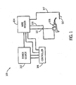
- a welding system 100 includes, in accordance with the preferred embodiment, a power supply 102, a wire feeder 104, a controller 106 and a torch 108, and a supply line 112 which feeds welding current, gas, water, control, and current for motors to torch 108, that cooperate to provide welding current on weld cables 105 and 107 to a workpiece 110.
- Power supply 102, wire feeder 104 and controller 106 may be commercially available welding system components, such as a Miller Invision 456® power supply, and a modified Miller XR® wire feeder.
- Power supply includes any device capable of supplying welding, plasma cutting, and/or induction heating power including resonant power supplies, quasi-resonant power supplies, etc., as well as control circuitry and other ancillary circuitry associated therewith.
- Power source, or source of power includes the power circuitry such as rectifiers, switches, transformers, SCARS, etc. that process and provide the output power.
- Wire feeder includes the motor or mechanism that drives the wire, the mounting for the wire, and controls related thereto, and associated hardware and software.
- Wire path includes the path the wire takes from the wire source to the torch or power supply, and may include through a liner, a buffer, etc.
- Controller 106 is part of wire feeder 104 and power supply 102 in this embodiment. Controller 106 also includes control modules adapted for the present invention, such as a reversible wire feeder control module to control the reversible motors, a mean arc current module, and the control module for the mechanical control of the arc states. Controller, as used herein, includes digital and analog circuitry, discrete or integrated circuitry, microprocessors, DIPS, etc., and software, hardware and firmware, located on one or more boards, used to control a device such as a power supply and/or wire feeder. Control module, as used herein, maybe digital or analog, and includes hardware or software, that performs a specified control function. For example, a mean arc current control module controls the output to provide a desired mean arc current.
- control module as used herein, maybe digital or analog, and includes hardware or software, that performs a specified control function. For example, a mean arc current control module controls the output to provide a desired mean arc current.
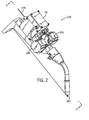
- Torch 108 includes, in addition to the features of prior art torches, a pair of motor housings 203 and 205 have motors disposed within to drive the wire to or from the weld, and a buffer 202. to take up wire 209 when it is retracted, and provide wire 209 when it is advanced.
- Buffer includes components used to take up the wire when the wire direction is reversed and provide wire when the wire is advanced.
- the end of the wire at the arc is shown as 207.
- the motor housings and buffer are adjacent to the torch in the preferred embodiment, and near the torch in other embodiments. Adjacent the torch, as used herein, includes abutting, touching or part of the torch, directly or through a housing. Near the torch, as used herein, includes much closer to the torch than the source of wire, such as more than 75% of the way from the source to the torch.
- a handheld torch includes a small spool of wire mounted on the torch.
- Figure 3 is a cross-sectional view of the torch of Figure 2, taken along lines A-A,
- a pair of motors 301 and 302 are preferably stepper motors (although they may be other motors) and drive the wire and are disposed adjacent to the wire, and directly opposite one another, on opposite sides of the wire, thereby substantially equalizing forces on the wire. In alternative embodiments they are disposed one following the other, or on the same side of the wire. Directly opposite one another, as used herein, includes at substantially the same position along a wire path. Disposed adjacent the wire, as used herein, includes being close enough to the wire to push or pull the wire. Drive the wire, as used herein, includes one or both of moving the wire toward the torch and moving the wire away from the torch.
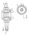
- Buffer 201 may also be seen on Figure 3, and is shown in more detail on Figure 4, and includes a shaft 401 mounted on a support 403. Shaft 401 has a hollow axis, through which wire 209 passes.
- Weld cable 105 ( Figures 1 and 5) is comprised of an outer tube 501 and a liner 503, with wire 209 disposed therein.
- the outer diameter of line 503 is substantially smaller than the inner diameter of tube 501, to allow for wire length to be taken up or stored by liner 503 flexing within tube 501.
- Liner 503 is preferably a coil spring that allows for compression and expansion to further buffer the wire. Storing a length of wire, as used herein, includes taking up wire when the wire direction is reversed.
- Wire liner includes a tube in which the wire can easily move. Tube 501 is mounted to shaft 401 so that wire 209 moves with respect to shaft 401.
- a sensor can be included that senses the amount of wire taken up by buffer 201.
- sensors include a wheel with an encoder that is turned as the wire moves past it, or a linear transformer, with the liner being comprised of a ferrite or magnetic material,
- the controller includes a buffer feedback input that receives the feedback 1 and provides a wire feed motor output that is responsive to the buffer feedback. Tension in the wire can also be sensed and used to control the process.
- One desirable control scheme uses mean arc current (average current during the arc state, or a function thereof) as the control variable. This allows better control of the melting and heat to the weld, and reduces spatter and instability, compared to prior art control schemes. It is possible to use mean arc current to control the heat, since arc current is not used to cause the transition from arc to short (or the opposite) .
- the control of the states can be coordinated with the current control. For example, if a state transition is to occur at a time Tl, the current transition can occur shortly before that, so as to avoid disrupting the weld pool.
- Another control feature is to allow the user to set relative arc and short time, or balance between EP and EN.
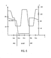
- One desirable arc waveform is shown in Figure 6, and includes an arc current waveform with three segments - an initial high current segment, an intermediate current segment, and a low current segment.
- the low current segment is entered into prior to the short forming, thereby enhancing a smooth transition to the short circuit state.
- the current can be set to the value, which directs the process into the wanted situation by physical determined behavior.
- the forces onto the liquid have to be low, when the cross section of the electrical conductor is low. Therefore, the currents have to be low during those states.
- high forces can be used to move liquids. Also, high currents during the middle part of the short circuit state are possible.
- the current can be used for movement of the liquid and determining the melting rate.
- the present invention may be used with known control schemes, but implement them in a more desirable fashion by eliminating the need for current levels to cause transitions.
- schemes using either arc length or stick-out as a control variable can be implemented easily because the stepper motors allow stick-out to be measured precisely. Because the transitions are caused mechanically, the arc length may be redetermined each process cycle.
- the present invention may be implemented with a variety of processes, including but not limited to electrode positive, electrode negative, alternating polarity, ac mig, mig brazing, hard facing, and welding with thick wire at low currents. For example, welding on a 2.4 mm or larger wire may be performed at 100 amps, or even 35 or fewer amps with the present invention.
- Prior art systems required more current on thick wire to cause the short to clear and to enter the arc state.
- the present invention doesn't rely on current to clear the short, so thick wire and low current may be used.
- the control preferably ties the speed of the wire feed motor to the average speed of the stepper motors, so that the wire feed speed follows the process speed. Averaging speed over 20-30 process cycles (about 500 msec.) provides for effective control.
- Pool oscillation frequency can be found by monitoring the distance the wire travels until a short is created, or an arc is created.
- One control scheme provides that the state transitions are timed to coincide with the natural frequency of pool oscillation.
- the controller includes a frequency module and a pool oscillation feedback circuit that effect this control scheme.
- a short detection feedback circuit may be used as part of the control loop.
Landscapes
- Engineering & Computer Science (AREA)
- Physics & Mathematics (AREA)
- Plasma & Fusion (AREA)
- Mechanical Engineering (AREA)
- Arc Welding Control (AREA)
Abstract
Description
Claims (10)
- A method of controlling a welding-type power supply comprising:providing a current wave form having an arc current portion and a short circuit current portion;causing an arc state to be entered by retracting a welding wire;causing a short circuit state to be entered by advancing the wire;causing the current to enter the arc current portion prior to the creation of the arc by coordinating the wave form with the wire retraction; and,causing the current to enter the short circuit current portion prior to the creation of the short by coordinating the wave form with the wire advancing.
- A method according to claim 1, further comprising controlling the penetration or bead formation by controlling the advancement of the wire into the weld pool.
- A method according to claim 1 or 2, wherein the current magnitude during the arc portion and the short portion is used to control heat applied to the weld, and wherein advancing and retracting the wire is used to control the time at which the process transitions from the arc state to the short circuit state and from the short circuit state to the arc state.
- A method of according to any one of the preceding claims, further comprising determining a time T1 for the transition between the arc state and the short circuit state, and retracting the wire such that the arc is created by time T1, and determining a time T2 for a transition from the arc state to the short circuit state, and retracting the wire such that the short circuit state is entered by the time T2.
- A method according to claim 4, further comprising changing the current wave form from the short circuit portion to the arc portion by the time Ti, and the changing the wave form from the arc portion to the short circuit portion by the time T2.
- A method according to any one of the preceding claims, further comprising controlling the portion of time the process spends in the arc state relative to the short circuit state, by controlling the length of time between the successive retraction and advancing of the wire.
- A method according to claim 6, further comprising receiving a user selectable input indicative of a desired arc state time relative to short circuit state time.
- A method according to any of the preceding claims, further comprising controlling the welding process to enter a pulse state, in addition to the arc state and the short circuit state, wherein the amount of time spent in the pulse state, relative to the short circuit state, is responsive to a user selectable input.
- A method according to claim 7 or 8, further comprising, controlling the mixture of gas from two or more sources in response to the users selectable input.
- A method according to any one of the preceding claims, further comprising controlling the penetration by controlling the polarity of the current, wherein the polarity is changed a plurality of times to control the penetration.
Priority Applications (1)
| Application Number | Priority Date | Filing Date | Title |
|---|---|---|---|
| EP10186198.7A EP2327499B1 (en) | 2002-07-23 | 2003-07-21 | Method of controlling a power supply for short circuit arc welding |
Applications Claiming Priority (2)
| Application Number | Priority Date | Filing Date | Title |
|---|---|---|---|
| US10/200,860 US6969823B2 (en) | 2002-07-23 | 2002-07-23 | Method and apparatus for controlling a welding system |
| US200860 | 2002-07-23 |
Related Child Applications (2)
| Application Number | Title | Priority Date | Filing Date |
|---|---|---|---|
| EP10186198.7A Division EP2327499B1 (en) | 2002-07-23 | 2003-07-21 | Method of controlling a power supply for short circuit arc welding |
| EP10186198.7 Division-Into | 2010-10-01 |
Publications (3)
| Publication Number | Publication Date |
|---|---|
| EP1384546A2 true EP1384546A2 (en) | 2004-01-28 |
| EP1384546A3 EP1384546A3 (en) | 2005-03-16 |
| EP1384546B1 EP1384546B1 (en) | 2011-06-29 |
Family
ID=30000073
Family Applications (2)
| Application Number | Title | Priority Date | Filing Date |
|---|---|---|---|
| EP03254551A Expired - Lifetime EP1384546B1 (en) | 2002-07-23 | 2003-07-21 | Method of controlling a power supply for short circuit arc welding |
| EP10186198.7A Revoked EP2327499B1 (en) | 2002-07-23 | 2003-07-21 | Method of controlling a power supply for short circuit arc welding |
Family Applications After (1)
| Application Number | Title | Priority Date | Filing Date |
|---|---|---|---|
| EP10186198.7A Revoked EP2327499B1 (en) | 2002-07-23 | 2003-07-21 | Method of controlling a power supply for short circuit arc welding |
Country Status (6)
| Country | Link |
|---|---|
| US (4) | US6969823B2 (en) |
| EP (2) | EP1384546B1 (en) |
| JP (1) | JP2004050293A (en) |
| CN (1) | CN1278811C (en) |
| AT (1) | ATE514512T1 (en) |
| CA (1) | CA2435863C (en) |
Cited By (17)
| Publication number | Priority date | Publication date | Assignee | Title |
|---|---|---|---|---|
| AT501489A1 (en) * | 2005-02-25 | 2006-09-15 | Fronius Int Gmbh | METHOD FOR CONTROLLING AND / OR REGULATING A WELDING DEVICE AND WELDING DEVICE |
| EP1710037A1 (en) * | 2005-04-05 | 2006-10-11 | Vermaat Technics B.V. | Apparatus and method for short-circuit arc welding |
| EP1726395A1 (en) * | 2005-05-27 | 2006-11-29 | EWM Hightec Welding GmbH | Welding power supply and procedure for MIG/MAG welding |
| WO2008137371A3 (en) * | 2007-04-30 | 2008-12-24 | Illinois Tool Works | Welding system and method with improved waveform |
| FR2923167A1 (en) * | 2007-11-06 | 2009-05-08 | Air Liquide | ARC WELDING METHOD BY SHORT CIRCUIT WITH FUSIBLE ELECTRODE |
| WO2011106175A1 (en) | 2010-02-23 | 2011-09-01 | Illinois Tool Works Inc. | Wire feed speed referenced variable frequency pulse welding system |
| US8035059B2 (en) | 2003-10-23 | 2011-10-11 | Fronius International Gmbh | Method for controlling and/or adjusting a welding process |
| DE102011007694A1 (en) | 2011-04-19 | 2012-10-25 | Robert Bosch Gmbh | Drilling tool or method for producing a drilling tool |
| DE102011085818A1 (en) | 2011-11-07 | 2013-05-08 | Robert Bosch Gmbh | Rock bits and method of making a rock bit |
| US9035220B2 (en) | 2005-05-24 | 2015-05-19 | Fronius International Gmbh | Cold-metal-transfer welding process and welding installation |
| WO2015125008A1 (en) * | 2014-02-24 | 2015-08-27 | Lincoln Global, Inc. | Method and system to use combination filler wire feed and high intensity energy source for welding with controlled arcing frequency |
| US20170189982A1 (en) * | 2015-12-31 | 2017-07-06 | Illinois Tool Works Inc. | Wire delivery apparatus with a non-rotational actuator |
| US9782850B2 (en) | 2009-01-13 | 2017-10-10 | Lincoln Global, Inc. | Method and system to start and use combination filler wire feed and high intensity energy source for welding |
| US10086461B2 (en) | 2009-01-13 | 2018-10-02 | Lincoln Global, Inc. | Method and system to start and use combination filler wire feed and high intensity energy source for welding |
| EP2327499B1 (en) | 2002-07-23 | 2018-12-05 | Illinois Tool Works Inc. | Method of controlling a power supply for short circuit arc welding |
| US10464168B2 (en) | 2014-01-24 | 2019-11-05 | Lincoln Global, Inc. | Method and system for additive manufacturing using high energy source and hot-wire |
| US11027362B2 (en) | 2017-12-19 | 2021-06-08 | Lincoln Global, Inc. | Systems and methods providing location feedback for additive manufacturing |
Families Citing this family (79)
| Publication number | Priority date | Publication date | Assignee | Title |
|---|---|---|---|---|
| US7356351B1 (en) * | 2000-12-22 | 2008-04-08 | Durham Logistics, Llc | Method and apparatus for disabling the RF functionality of a multi-function wireless communication device while maintaining local functionality |
| US6963048B2 (en) * | 2002-07-23 | 2005-11-08 | Illinois Tool Works Inc. | Method and apparatus for welding with mechanical arc control |
| US7165707B2 (en) * | 2002-07-23 | 2007-01-23 | Illinois Tool Works Inc. | Method and apparatus for feeding wire to a welding arc |
| US7102099B2 (en) * | 2002-07-23 | 2006-09-05 | Illinois Tool Works Inc. | Method and apparatus for feeding wire to a welding arc |
| US6984806B2 (en) * | 2002-07-23 | 2006-01-10 | Illinois Tool Works Inc. | Method and apparatus for retracting and advancing a welding wire |
| GB2403334B (en) * | 2003-06-26 | 2005-05-11 | Abdol Hosain Akbarpour | Electromechanical display mechanism |
| EP1512481A3 (en) * | 2003-09-02 | 2011-09-28 | Illinois Tool Works Inc. | Voltage regulated GMA welding using a constant current power source and wire feeder having variable gain |
| US7091449B2 (en) * | 2003-09-02 | 2006-08-15 | Illinois Tool Works Inc. | Voltage regulated MIG welding using a constant current power source |
| US9000329B2 (en) * | 2004-07-22 | 2015-04-07 | Illinois Tool Works Inc. | Welding arc stabilization process |
| US7323659B2 (en) * | 2004-09-28 | 2008-01-29 | Illinois Tool Works Inc. | System and method of precise wire feed control in a welder |
| EP1745880B1 (en) * | 2005-04-14 | 2011-08-03 | Panasonic Corporation | Consumable electrode arc-welding machine |
| DE102005040552A1 (en) * | 2005-08-26 | 2007-03-01 | Linde Ag | Method of arc joining |
| US8766141B2 (en) | 2006-07-21 | 2014-07-01 | Illinois Tool Works Inc. | Welding system having a wire-specific interface |
| US20080035623A1 (en) * | 2006-08-11 | 2008-02-14 | Illinois Tool Works Inc. | Contact tip and assembly |
| DE102007009572A1 (en) | 2007-02-27 | 2008-08-28 | Linde Ag | Method for the electric arc joining of workpieces comprises using a protective gas containing carbon dioxide, helium and argon |
| US20080264923A1 (en) * | 2007-04-30 | 2008-10-30 | Illinois Tool Works Inc. | Welding system and method with improved waveform |
| US9895760B2 (en) * | 2007-09-26 | 2018-02-20 | Lincoln Global, Inc. | Method and system to increase heat input to a weld during a short-circuit arc welding process |
| US9415458B2 (en) * | 2007-09-26 | 2016-08-16 | Lincoln Global, Inc. | Method to improve the characteristics of a root pass pipe weld |
| DE102008024977A1 (en) | 2008-05-23 | 2009-11-26 | Linde Ag | Method of arc joining |
| KR101026980B1 (en) * | 2008-09-16 | 2011-04-11 | 스웰 주식회사 | Digital Pulse Age Welding Device |
| FR2935277A1 (en) * | 2009-04-01 | 2010-03-05 | Air Liquide | DOUBLE CURRENT ARC WELDING PROCESS. |
| AT508146B1 (en) | 2009-08-10 | 2010-11-15 | Fronius Int Gmbh | METHOD FOR DISCONNECTING A SHORT CIRCUIT FOR SHORT ARC WELDING AND WELDING DEVICE FOR SHORT ARC WELDING |
| DE102010038302A1 (en) | 2010-07-22 | 2012-01-26 | Linde Aktiengesellschaft | Method for short arc tandem welding |
| US10183353B2 (en) | 2010-09-17 | 2019-01-22 | Illinois Tool Works Inc. | Method and apparatus for welding with reduced spatter |
| US20120241431A1 (en) * | 2011-03-25 | 2012-09-27 | Hobart Brothers Company | Welding arc powered spool gun |
| US10525546B2 (en) | 2011-05-23 | 2020-01-07 | Azz Wsi Llc | Welding apparatus having a wire pulser and methods thereof |
| CN103747912B (en) | 2011-05-26 | 2016-08-17 | 维克托设备公司 | The system producing welding and the method for the Correction and Control welding machine utilizing voltage based on the welding output calculated and wire feed rate |
| CA2837384A1 (en) | 2011-05-26 | 2012-11-29 | Thermal Dynamics Corporation | Welding process with provision of a pulse period at the start |
| US8803034B2 (en) | 2012-01-17 | 2014-08-12 | Lincoln Global, Inc. | Systems and methods to feed wire within a welder |
| US9050676B2 (en) | 2012-03-02 | 2015-06-09 | Lincoln Global, Inc. | Apparatus and method for starting arc welding process |
| JP5540391B2 (en) * | 2012-11-15 | 2014-07-02 | 国立大学法人大阪大学 | GMA welding method |
| US10040143B2 (en) | 2012-12-12 | 2018-08-07 | Illinois Tool Works Inc. | Dabbing pulsed welding system and method |
| US10906114B2 (en) * | 2012-12-21 | 2021-02-02 | Illinois Tool Works Inc. | System for arc welding with enhanced metal deposition |
| US9950383B2 (en) | 2013-02-05 | 2018-04-24 | Illinois Tool Works Inc. | Welding wire preheating system and method |
| US10835983B2 (en) | 2013-03-14 | 2020-11-17 | Illinois Tool Works Inc. | Electrode negative pulse welding system and method |
| JP5598568B2 (en) * | 2013-05-14 | 2014-10-01 | パナソニック株式会社 | Welding apparatus and welding method |
| JP5994735B2 (en) * | 2013-06-07 | 2016-09-21 | 株式会社安川電機 | Arc welding apparatus, arc welding system, and arc welding method |
| US11045891B2 (en) | 2013-06-13 | 2021-06-29 | Illinois Tool Works Inc. | Systems and methods for anomalous cathode event control |
| US10543549B2 (en) | 2013-07-16 | 2020-01-28 | Illinois Tool Works Inc. | Additive manufacturing system for joining and surface overlay |
| US10828728B2 (en) | 2013-09-26 | 2020-11-10 | Illinois Tool Works Inc. | Hotwire deposition material processing system and method |
| US10052707B2 (en) * | 2014-04-04 | 2018-08-21 | Lincoln Global, Inc. | Method and system to use AC welding waveform and enhanced consumable to improve welding of galvanized workpiece |
| US11154946B2 (en) | 2014-06-30 | 2021-10-26 | Illinois Tool Works Inc. | Systems and methods for the control of welding parameters |
| US11198189B2 (en) | 2014-09-17 | 2021-12-14 | Illinois Tool Works Inc. | Electrode negative pulse welding system and method |
| US11478870B2 (en) | 2014-11-26 | 2022-10-25 | Illinois Tool Works Inc. | Dabbing pulsed welding system and method |
| US10189106B2 (en) | 2014-12-11 | 2019-01-29 | Illinois Tool Works Inc. | Reduced energy welding system and method |
| US11370050B2 (en) | 2015-03-31 | 2022-06-28 | Illinois Tool Works Inc. | Controlled short circuit welding system and method |
| US10974337B2 (en) | 2015-08-17 | 2021-04-13 | Illinois Tool Works Inc. | Additive manufacturing systems and methods |
| US11285559B2 (en) | 2015-11-30 | 2022-03-29 | Illinois Tool Works Inc. | Welding system and method for shielded welding wires |
| US10610946B2 (en) | 2015-12-07 | 2020-04-07 | Illinois Tool Works, Inc. | Systems and methods for automated root pass welding |
| US10675699B2 (en) | 2015-12-10 | 2020-06-09 | Illinois Tool Works Inc. | Systems, methods, and apparatus to preheat welding wire |
| US12194579B2 (en) | 2015-12-10 | 2025-01-14 | Illinois Tool Works Inc. | Systems, methods, and apparatus to preheat welding wire |
| US10730132B2 (en) | 2015-12-28 | 2020-08-04 | Illinois Tool Works Inc. | Reciprocating wire feed welding system and method |
| EP3702084A1 (en) * | 2016-03-11 | 2020-09-02 | Daihen Corporation | Arc welding system and wire feeding device |
| US10906120B2 (en) | 2016-06-10 | 2021-02-02 | Illinois Tool Works Inc. | Methods and apparatus to provide a consistent electrode state for welding |
| WO2018074267A1 (en) | 2016-10-18 | 2018-04-26 | 株式会社ダイヘン | Wire feeding device and arc welding device |
| US10449615B2 (en) * | 2016-10-31 | 2019-10-22 | Illinois Tool Works Inc. | Hybrid welding modules |
| WO2018131345A1 (en) * | 2017-01-16 | 2018-07-19 | 株式会社ダイヘン | Arc start control method for forward and reverse feeding arc welding |
| US20180207744A1 (en) * | 2017-01-26 | 2018-07-26 | Genesis Systems Group, Llc | Sensor for weld wire supply drum |
| US11110536B2 (en) * | 2017-01-27 | 2021-09-07 | Lincoln Global, Inc. | Apparatus and method for welding with AC waveform |
| US10500671B2 (en) | 2017-04-06 | 2019-12-10 | Lincoln Global, Inc. | System and method for arc welding and wire manipulation control |
| US10766092B2 (en) | 2017-04-18 | 2020-09-08 | Illinois Tool Works Inc. | Systems, methods, and apparatus to provide preheat voltage feedback loss protection |
| US10870164B2 (en) | 2017-05-16 | 2020-12-22 | Illinois Tool Works Inc. | Systems, methods, and apparatus to preheat welding wire |
| EP3634684B1 (en) | 2017-06-09 | 2022-10-05 | Illinois Tool Works Inc. | Welding torch with a first contact tip to preheat welding wire and a second contact tip |
| CN111386168A (en) | 2017-06-09 | 2020-07-07 | 伊利诺斯工具制品有限公司 | Welding assembly for a welding torch with two contact tips and a cooling body for cooling and conducting electric current |
| CN111315524A (en) | 2017-06-09 | 2020-06-19 | 伊利诺斯工具制品有限公司 | Welding torch with two contacts and multiple liquid-cooled components for conducting current to the contacts |
| US11590598B2 (en) | 2017-06-09 | 2023-02-28 | Illinois Tool Works Inc. | Systems, methods, and apparatus to preheat welding wire |
| US11524354B2 (en) | 2017-06-09 | 2022-12-13 | Illinois Tool Works Inc. | Systems, methods, and apparatus to control weld current in a preheating system |
| US11020813B2 (en) | 2017-09-13 | 2021-06-01 | Illinois Tool Works Inc. | Systems, methods, and apparatus to reduce cast in a welding wire |
| US10792682B2 (en) | 2017-10-02 | 2020-10-06 | Illinois Tool Works Inc. | Metal manufacturing systems and methods using mechanical oscillation |
| JP7039301B2 (en) * | 2018-01-24 | 2022-03-22 | 株式会社ダイヘン | Wire feeding device, arc welding device and wire feeding method |
| CN113165097B (en) | 2018-08-31 | 2023-11-03 | 伊利诺斯工具制品有限公司 | Submerged arc welding systems and submerged arc welding torches for resistively preheating the electrode wire |
| US11014185B2 (en) | 2018-09-27 | 2021-05-25 | Illinois Tool Works Inc. | Systems, methods, and apparatus for control of wire preheating in welding-type systems |
| EP3898055A2 (en) | 2018-12-19 | 2021-10-27 | Illinois Tool Works, Inc. | Contact tip, wire preheating assembly, contact tip assembly and consumable electrode-fed welding type system |
| US12465992B2 (en) * | 2019-01-31 | 2025-11-11 | Illinois Tool Works Inc. | Systems and methods for controlled arc and short phase time adjustment |
| US12583048B2 (en) | 2019-03-29 | 2026-03-24 | Illinois Tool Works Inc. | Methods and apparatus to convert welding-type power to welding-type power and resistive preheating power |
| US12103121B2 (en) | 2019-04-30 | 2024-10-01 | Illinois Tool Works Inc. | Methods and apparatus to control welding power and preheating power |
| EP3772389A1 (en) * | 2019-08-06 | 2021-02-10 | Fronius International GmbH | Method and device for stabilizing a transition between different welding process phases of a welding process |
| US11772182B2 (en) | 2019-12-20 | 2023-10-03 | Illinois Tool Works Inc. | Systems and methods for gas control during welding wire pretreatments |
| CN111085755A (en) * | 2020-01-10 | 2020-05-01 | 石家庄华俊科技有限公司 | Welding rod welding machine control method, device and system and terminal equipment |
Family Cites Families (86)
| Publication number | Priority date | Publication date | Assignee | Title |
|---|---|---|---|---|
| US1563612A (en) * | 1923-07-24 | 1925-12-01 | Cutler Arthur Edward | Electric welding apparatus |
| US1927896A (en) * | 1930-05-22 | 1933-09-26 | Westinghouse Electric & Mfg Co | Automatic welding device |
| US2079956A (en) * | 1934-03-16 | 1937-05-11 | Una Welding Inc | Automatic welding head |
| US2886696A (en) * | 1958-04-02 | 1959-05-12 | Air Reduction | Electric arc welding |
| US3139506A (en) * | 1958-10-28 | 1964-06-30 | Linde Eismasch Ag | Protective gas mixture for light arc welding with a fusible blank wire electrode |
| US3053975A (en) * | 1960-03-11 | 1962-09-11 | Exxon Research Engineering Co | Apparatus and method for arc welding |
| US3249276A (en) * | 1963-11-15 | 1966-05-03 | Philips Corp | Electric arc welding apparatus |
| US3344305A (en) * | 1965-12-06 | 1967-09-26 | Ogden Eng Corp | Tandem drive welding wire feed arrangement for semi-automatic welding equipment |
| US3339057A (en) * | 1966-07-28 | 1967-08-29 | Arthur A Bernard | Mechanical intermittent arc welding |
| US3581053A (en) * | 1967-12-05 | 1971-05-25 | Union Carbide Corp | Synchro-arc metal transfer |
| US3630425A (en) * | 1968-04-20 | 1971-12-28 | Messer Griesheim Gmbh | Electrode wire advance for arc welding |
| US3639858A (en) * | 1968-08-31 | 1972-02-01 | Mitsumi Electric Co Ltd | Transistor impedance converter and oscillator circuits |
| SE374291B (en) * | 1968-09-16 | 1975-03-03 | Osaka Transformer Co Ltd | |
| US3586221A (en) * | 1969-08-28 | 1971-06-22 | Air Reduction | Torque control of multiple motors for uniform feed of welding wire |
| JPS4825633B1 (en) * | 1970-07-24 | 1973-07-30 | ||
| NL176060B (en) * | 1974-02-08 | 1984-09-17 | Philips Nv | WELDING DEVICE FOR SHORT ARC WELDING. |
| US4125759A (en) * | 1974-10-17 | 1978-11-14 | Osaka Transformer Co., Ltd. | Method and apparatus for shortcircuiting arc welding |
| US3975616A (en) * | 1974-11-13 | 1976-08-17 | The Lincoln Electric Company | Control circuit for automatic electric arc-welder |
| SE396898B (en) | 1976-02-06 | 1977-10-10 | Elektriska Svetsnings Ab | PROCEDURE IN PREPARING A BUMP WELDING BETWEEN TWO THICK-WALL WORKPIECES |
| US4159410A (en) * | 1977-06-13 | 1979-06-26 | General Electric Company | Method and apparatus for applying molten filler material |
| CH621724A5 (en) | 1977-08-18 | 1981-02-27 | Oerlikon Buehrle Schweisstech | |
| JPS54109054A (en) * | 1978-02-15 | 1979-08-27 | Yoshida Keiichiro | Method and apparatus for stretching material |
| JPS569062A (en) | 1979-07-02 | 1981-01-29 | Mitsubishi Electric Corp | Consumable electrode type gas shielded arc welding equipment |
| US4288682A (en) | 1979-11-28 | 1981-09-08 | Union Carbide Corporation | Welding system with reversible drive motor control |
| US4301355A (en) * | 1980-08-04 | 1981-11-17 | Dimetrics, Inc. | Gas metal arc welding system |
| US4441012A (en) * | 1981-12-14 | 1984-04-03 | General Electric Company | Method and apparatus for controlling heating power during the application of molten filler material to a workpiece |
| DE3200421A1 (en) | 1982-01-09 | 1983-07-21 | Messer Griesheim Gmbh, 6000 Frankfurt | Planetary roller feed for a consumable welding wire |
| JPS58151966A (en) * | 1982-03-03 | 1983-09-09 | Nippon Steel Weld Prod & Eng Co Ltd | Feeding device of welding wire |
| GB2120692B (en) | 1982-05-14 | 1986-07-16 | Welding Inst | Improvements relating to wire supplying |
| US4546234A (en) * | 1983-08-11 | 1985-10-08 | Kabushiki Kaisha Kobe Seiko Sho | Output control of short circuit welding power source |
| US4553018A (en) * | 1983-10-27 | 1985-11-12 | Mitsubishi Denki Kabushiki Kaisha | Short circuiting transfer arc welding machine |
| JPS60108176A (en) | 1983-11-18 | 1985-06-13 | Osaka Denki Kk | Arc starting method in consumable electrode type arc welding method |
| JPS60180675A (en) | 1984-02-28 | 1985-09-14 | Mitsubishi Heavy Ind Ltd | Consumable electrode type pulse arc welding method |
| US4954691A (en) * | 1986-12-10 | 1990-09-04 | The Lincoln Electric Company | Method and device for controlling a short circuiting type welding system |
| US4835360A (en) * | 1986-12-11 | 1989-05-30 | The Lincoln Electric Company | Method and device for controlling a short circuiting type welding system |
| US4972064A (en) * | 1986-12-11 | 1990-11-20 | The Lincoln Electric Company | Apparatus for short circuiting arc welding |
| US5001326A (en) * | 1986-12-11 | 1991-03-19 | The Lincoln Electric Company | Apparatus and method of controlling a welding cycle |
| US4717807A (en) * | 1986-12-11 | 1988-01-05 | The Lincoln Electric Company | Method and device for controlling a short circuiting type welding system |
| US5148001A (en) * | 1986-12-11 | 1992-09-15 | The Lincoln Electric Company | System and method of short circuiting arc welding |
| US4866247A (en) * | 1986-12-11 | 1989-09-12 | The Lincoln Electric Company | Apparatus and method of short circuiting arc welding |
| US5003154A (en) * | 1986-12-11 | 1991-03-26 | The Lincoln Electric Company | Apparatus and method of short circuiting arc welding |
| US4897523A (en) * | 1986-12-11 | 1990-01-30 | The Lincoln Electric Company | Apparatus and method of short circuiting arc welding |
| US4780594A (en) | 1987-10-08 | 1988-10-25 | Dimetrics Inc. | Method and apparatus for improved control of supply of filler material to a welding location |
| FR2624418A1 (en) | 1987-12-11 | 1989-06-16 | Renault | SELF-ADAPTIVE DRIVE DEVICE FOR SUPPLYING WELDING WELDING TORCHES |
| AU596761B2 (en) | 1987-12-21 | 1990-05-10 | Lincoln Electric Company, The | Apparatus and method of short circuiting arc welding |
| DE3827508A1 (en) | 1988-08-12 | 1990-02-15 | Kuka Schweissanlagen & Roboter | Transport arrangement for the welding-wire feed on welding equipment |
| AT394675B (en) | 1988-11-03 | 1992-05-25 | Fronius Schweissmasch | WIRE FEEDING DEVICE FOR A PROTECTIVE GAS WELDING MACHINE |
| KR100219813B1 (en) * | 1990-04-17 | 1999-09-01 | 니시마쓰 다이조 | MAG arc welding method and welding device |
| SU1743752A1 (en) | 1990-10-01 | 1992-06-30 | Завод "Прогресс" Им.Маршала Советского Союза Устинова Д.Ф. | Consumable-electrode arc welder |
| DE4118208A1 (en) | 1991-06-04 | 1991-11-07 | Veit Dr Thomas | Fast viewed displays control under variable lighting - uses light sensors for intensity, direction and spectrum and has liquid-crystal viewing panels |
| JP2607997B2 (en) * | 1991-10-18 | 1997-05-07 | 株式会社三社電機製作所 | Arc welding machine |
| US5370290A (en) * | 1992-02-12 | 1994-12-06 | Gilliland; Malcolm T. | Wire feeder allowing for wire slippage without damaging wire |
| DE4204661C1 (en) | 1992-02-17 | 1993-06-24 | Weltron Steuerungs Schweissanlagenbau | Intermittent submerged arc welding seams mfr. - with wire feed reversal at end of weld for reliable reignition of arc |
| JP3149614B2 (en) | 1993-03-31 | 2001-03-26 | 松下電器産業株式会社 | Arc welding method for arc welding equipment |
| JPH0734332A (en) | 1993-07-21 | 1995-02-03 | Hara Shiyokuki Seisakusho:Kk | Method for swinging nipper frame of comber and apparatus therefor |
| US5643479A (en) * | 1995-11-14 | 1997-07-01 | Lloyd; Robert D. | Electric arc welding |
| US5742029A (en) * | 1996-07-15 | 1998-04-21 | The Lincoln Electric Company | Method of welding wallpaper alloy an arc welder modified to practice same |
| SE511463C2 (en) * | 1997-03-03 | 1999-10-04 | Esab Ab | Method of arc welding with melting electrode |
| DE19738785C2 (en) | 1997-09-04 | 2001-12-13 | Leipold & Co Gmbh | Arc welding device with melting electrode |
| ATE260730T1 (en) | 1997-09-29 | 2004-03-15 | Fronius Int Gmbh | METHOD FOR IGNITING AN ARC BETWEEN A WORKPIECE AND A CONFUSING ELECTRODE |
| US5961863A (en) * | 1998-01-09 | 1999-10-05 | Lincoln Global, Inc. | Short circuit pipe welding |
| US6051810A (en) * | 1998-01-09 | 2000-04-18 | Lincoln Global, Inc. | Short circuit welder |
| US6088470A (en) * | 1998-01-27 | 2000-07-11 | Sensar, Inc. | Method and apparatus for removal of bright or dark spots by the fusion of multiple images |
| US6087626A (en) * | 1998-02-17 | 2000-07-11 | Illinois Tool Works Inc. | Method and apparatus for welding |
| JP4317998B2 (en) | 1998-02-18 | 2009-08-19 | 東芝プラントシステム株式会社 | MIG welding or MAG welding method |
| JPH11267839A (en) | 1998-03-18 | 1999-10-05 | Yaskawa Electric Corp | Arc welding method |
| US6008470A (en) | 1998-03-26 | 1999-12-28 | University Of Kentucky Research Foundation | Method and system for gas metal arc welding |
| US5973291A (en) * | 1998-08-11 | 1999-10-26 | Lincoln Global, Inc. | Method and system for determining the feedability of welding wire |
| US6297473B2 (en) * | 1998-09-04 | 2001-10-02 | Japan As Represented By Director General Of National Research Institute For Metals | Arc welding method |
| US6160241A (en) | 1999-03-16 | 2000-12-12 | Lincoln Global, Inc. | Method and apparatus for electric arc welding |
| EP1182001B1 (en) * | 1999-03-18 | 2004-09-01 | Kabushiki Kaisha Yaskawa Denki | Consumable electrode type arc welding method and device therefor |
| AT409832B (en) | 1999-04-26 | 2002-11-25 | Fronius Schweissmasch Prod | WELDING PROCESS AND WELDING DEVICE FOR CARRYING OUT THE WELDING PROCESS |
| US6201216B1 (en) * | 1999-07-19 | 2001-03-13 | Lincoln Global, Inc. | Method and system for welding railroad rails |
| AT411032B (en) | 1999-11-19 | 2003-09-25 | Fronius Schweissmasch Prod | METHOD AND DEVICE FOR MONITORING A CONVEYOR |
| AUPQ528400A0 (en) * | 2000-01-27 | 2000-02-17 | Crc For Welded Structures Limited | A welding control system |
| US6518545B1 (en) * | 2000-02-25 | 2003-02-11 | Serimer Dasa | Welding arc penetrating power real-time detection system |
| DE10033387C2 (en) | 2000-07-08 | 2002-11-07 | Nimak Lichtbogenschweismaschin | Method and device for welding or soldering metal using a pulsed arc |
| US6501049B2 (en) | 2001-01-23 | 2002-12-31 | Lincoln Global, Inc. | Short circuit arc welder and method of controlling same |
| US6624388B1 (en) * | 2001-01-25 | 2003-09-23 | The Lincoln Electric Company | System and method providing distributed welding architecture |
| US6568578B1 (en) * | 2001-03-02 | 2003-05-27 | Mk Products | Welding wire feed mechanism |
| US6472634B1 (en) * | 2001-04-17 | 2002-10-29 | Lincoln Global, Inc. | Electric arc welding system |
| US6794608B2 (en) * | 2001-10-30 | 2004-09-21 | Tri Tool Inc. | Welding current control system and method |
| AUPS274002A0 (en) | 2002-06-03 | 2002-06-20 | University Of Wollongong, The | Control method and system for metal arc welding |
| US6984806B2 (en) | 2002-07-23 | 2006-01-10 | Illinois Tool Works Inc. | Method and apparatus for retracting and advancing a welding wire |
| US6963048B2 (en) | 2002-07-23 | 2005-11-08 | Illinois Tool Works Inc. | Method and apparatus for welding with mechanical arc control |
| US6969823B2 (en) | 2002-07-23 | 2005-11-29 | Illinois Tool Works Inc. | Method and apparatus for controlling a welding system |
-
2002
- 2002-07-23 US US10/200,860 patent/US6969823B2/en not_active Expired - Lifetime
-
2003
- 2003-07-16 JP JP2003197832A patent/JP2004050293A/en active Pending
- 2003-07-21 EP EP03254551A patent/EP1384546B1/en not_active Expired - Lifetime
- 2003-07-21 EP EP10186198.7A patent/EP2327499B1/en not_active Revoked
- 2003-07-21 AT AT03254551T patent/ATE514512T1/en active
- 2003-07-22 CN CNB031464467A patent/CN1278811C/en not_active Expired - Lifetime
- 2003-07-23 CA CA002435863A patent/CA2435863C/en not_active Expired - Fee Related
-
2004
- 2004-09-16 US US10/942,686 patent/US20050056629A1/en not_active Abandoned
-
2006
- 2006-03-28 US US11/277,701 patent/US7351933B2/en not_active Expired - Lifetime
-
2008
- 2008-02-20 US US12/034,074 patent/US20080149610A1/en not_active Abandoned
Cited By (29)
| Publication number | Priority date | Publication date | Assignee | Title |
|---|---|---|---|---|
| EP2327499B1 (en) | 2002-07-23 | 2018-12-05 | Illinois Tool Works Inc. | Method of controlling a power supply for short circuit arc welding |
| US8035059B2 (en) | 2003-10-23 | 2011-10-11 | Fronius International Gmbh | Method for controlling and/or adjusting a welding process |
| AT501489B1 (en) * | 2005-02-25 | 2009-07-15 | Fronius Int Gmbh | METHOD FOR CONTROLLING AND / OR REGULATING A WELDING DEVICE AND WELDING DEVICE |
| US9012808B2 (en) | 2005-02-25 | 2015-04-21 | Fronius International Gmbh | Method for controlling and/or regulating a welding apparatus, and welding apparatus |
| AT501489A1 (en) * | 2005-02-25 | 2006-09-15 | Fronius Int Gmbh | METHOD FOR CONTROLLING AND / OR REGULATING A WELDING DEVICE AND WELDING DEVICE |
| EP1710037A1 (en) * | 2005-04-05 | 2006-10-11 | Vermaat Technics B.V. | Apparatus and method for short-circuit arc welding |
| US9035220B2 (en) | 2005-05-24 | 2015-05-19 | Fronius International Gmbh | Cold-metal-transfer welding process and welding installation |
| EP1726395A1 (en) * | 2005-05-27 | 2006-11-29 | EWM Hightec Welding GmbH | Welding power supply and procedure for MIG/MAG welding |
| WO2008137371A3 (en) * | 2007-04-30 | 2008-12-24 | Illinois Tool Works | Welding system and method with improved waveform |
| FR2923167A1 (en) * | 2007-11-06 | 2009-05-08 | Air Liquide | ARC WELDING METHOD BY SHORT CIRCUIT WITH FUSIBLE ELECTRODE |
| EP2058078A1 (en) | 2007-11-06 | 2009-05-13 | Air Liquide Welding France | Method of arc welding by short circuit with fusible electrode |
| US10086461B2 (en) | 2009-01-13 | 2018-10-02 | Lincoln Global, Inc. | Method and system to start and use combination filler wire feed and high intensity energy source for welding |
| US9782850B2 (en) | 2009-01-13 | 2017-10-10 | Lincoln Global, Inc. | Method and system to start and use combination filler wire feed and high intensity energy source for welding |
| WO2011106175A1 (en) | 2010-02-23 | 2011-09-01 | Illinois Tool Works Inc. | Wire feed speed referenced variable frequency pulse welding system |
| US8395085B2 (en) | 2010-02-23 | 2013-03-12 | Illinois Tool Works Inc. | Wire feed speed referenced variable frequency pulse welding system |
| CN102770229B (en) * | 2010-02-23 | 2015-02-25 | 伊利诺斯工具制品有限公司 | Variable Frequency Pulse Welding System with Reference Wire Feeding Speed |
| CN102770229A (en) * | 2010-02-23 | 2012-11-07 | 伊利诺斯工具制品有限公司 | Welding system with wire feed speed reference variable frequency pulse |
| WO2012143174A1 (en) | 2011-04-19 | 2012-10-26 | Robert Bosch Gmbh | Drilling tool and method for producing a drilling tool |
| DE102011007694A1 (en) | 2011-04-19 | 2012-10-25 | Robert Bosch Gmbh | Drilling tool or method for producing a drilling tool |
| DE102011085818A1 (en) | 2011-11-07 | 2013-05-08 | Robert Bosch Gmbh | Rock bits and method of making a rock bit |
| WO2013068152A1 (en) | 2011-11-07 | 2013-05-16 | Robert Bosch Gmbh | Stone chisel, and method for producing a stone chisel |
| US10464168B2 (en) | 2014-01-24 | 2019-11-05 | Lincoln Global, Inc. | Method and system for additive manufacturing using high energy source and hot-wire |
| WO2015125008A1 (en) * | 2014-02-24 | 2015-08-27 | Lincoln Global, Inc. | Method and system to use combination filler wire feed and high intensity energy source for welding with controlled arcing frequency |
| US20170189982A1 (en) * | 2015-12-31 | 2017-07-06 | Illinois Tool Works Inc. | Wire delivery apparatus with a non-rotational actuator |
| WO2017116855A1 (en) * | 2015-12-31 | 2017-07-06 | Illinois Tool Works Inc. | Wire delivery apparatus with a non-rotational actuator |
| CN108472760A (en) * | 2015-12-31 | 2018-08-31 | 伊利诺斯工具制品有限公司 | Welding wire conveying equipment with non-rotating actuator |
| US10675698B2 (en) | 2015-12-31 | 2020-06-09 | Illinois Tool Works Inc. | Wire delivery apparatus with a non-rotational actuator |
| CN108472760B (en) * | 2015-12-31 | 2021-06-25 | 伊利诺斯工具制品有限公司 | Wire feed equipment with non-rotating actuator |
| US11027362B2 (en) | 2017-12-19 | 2021-06-08 | Lincoln Global, Inc. | Systems and methods providing location feedback for additive manufacturing |
Also Published As
| Publication number | Publication date |
|---|---|
| EP2327499B1 (en) | 2018-12-05 |
| US20050056629A1 (en) | 2005-03-17 |
| US20040016737A1 (en) | 2004-01-29 |
| CA2435863A1 (en) | 2004-01-23 |
| EP2327499A3 (en) | 2015-11-04 |
| JP2004050293A (en) | 2004-02-19 |
| US7351933B2 (en) | 2008-04-01 |
| CA2435863C (en) | 2007-01-09 |
| EP1384546A3 (en) | 2005-03-16 |
| EP1384546B1 (en) | 2011-06-29 |
| ATE514512T1 (en) | 2011-07-15 |
| US20080149610A1 (en) | 2008-06-26 |
| EP2327499A2 (en) | 2011-06-01 |
| CN1278811C (en) | 2006-10-11 |
| US6969823B2 (en) | 2005-11-29 |
| US20060169683A1 (en) | 2006-08-03 |
| CN1478629A (en) | 2004-03-03 |
Similar Documents
| Publication | Publication Date | Title |
|---|---|---|
| EP2327499B1 (en) | Method of controlling a power supply for short circuit arc welding | |
| US7554056B2 (en) | Method and apparatus for braking and advancing a welding wire | |
| US7364059B2 (en) | Method and apparatus for feeding wire to a welding arc | |
| EP1384548B1 (en) | Method and apparatus for welding with mechanical arc control | |
| US7102099B2 (en) | Method and apparatus for feeding wire to a welding arc | |
| EP1577044B1 (en) | Method for feeding wire to a welding arc | |
| AU2007231786B2 (en) | Method and apparatus for feeding wire to a welding arc | |
| CA2489137C (en) | Method and appartus for feeding wire to a welding arc |
Legal Events
| Date | Code | Title | Description |
|---|---|---|---|
| PUAI | Public reference made under article 153(3) epc to a published international application that has entered the european phase |
Free format text: ORIGINAL CODE: 0009012 |
|
| AK | Designated contracting states |
Kind code of ref document: A2 Designated state(s): AT BE BG CH CY CZ DE DK EE ES FI FR GB GR HU IE IT LI LU MC NL PT RO SE SI SK TR |
|
| AX | Request for extension of the european patent |
Extension state: AL LT LV MK |
|
| PUAL | Search report despatched |
Free format text: ORIGINAL CODE: 0009013 |
|
| AK | Designated contracting states |
Kind code of ref document: A3 Designated state(s): AT BE BG CH CY CZ DE DK EE ES FI FR GB GR HU IE IT LI LU MC NL PT RO SE SI SK TR |
|
| AX | Request for extension of the european patent |
Extension state: AL LT LV MK |
|
| 17P | Request for examination filed |
Effective date: 20050906 |
|
| AKX | Designation fees paid |
Designated state(s): AT DE FR GB IT |
|
| GRAP | Despatch of communication of intention to grant a patent |
Free format text: ORIGINAL CODE: EPIDOSNIGR1 |
|
| GRAS | Grant fee paid |
Free format text: ORIGINAL CODE: EPIDOSNIGR3 |
|
| GRAA | (expected) grant |
Free format text: ORIGINAL CODE: 0009210 |
|
| AK | Designated contracting states |
Kind code of ref document: B1 Designated state(s): AT DE FR GB IT |
|
| REG | Reference to a national code |
Ref country code: GB Ref legal event code: FG4D |
|
| REG | Reference to a national code |
Ref country code: DE Ref legal event code: R096 Ref document number: 60337535 Country of ref document: DE Effective date: 20110818 |
|
| PLBE | No opposition filed within time limit |
Free format text: ORIGINAL CODE: 0009261 |
|
| STAA | Information on the status of an ep patent application or granted ep patent |
Free format text: STATUS: NO OPPOSITION FILED WITHIN TIME LIMIT |
|
| GBPC | Gb: european patent ceased through non-payment of renewal fee |
Effective date: 20110929 |
|
| 26N | No opposition filed |
Effective date: 20120330 |
|
| REG | Reference to a national code |
Ref country code: DE Ref legal event code: R097 Ref document number: 60337535 Country of ref document: DE Effective date: 20120330 |
|
| PG25 | Lapsed in a contracting state [announced via postgrant information from national office to epo] |
Ref country code: GB Free format text: LAPSE BECAUSE OF NON-PAYMENT OF DUE FEES Effective date: 20110929 |
|
| REG | Reference to a national code |
Ref country code: FR Ref legal event code: PLFP Year of fee payment: 13 |
|
| REG | Reference to a national code |
Ref country code: FR Ref legal event code: PLFP Year of fee payment: 14 |
|
| REG | Reference to a national code |
Ref country code: FR Ref legal event code: PLFP Year of fee payment: 15 |
|
| PGFP | Annual fee paid to national office [announced via postgrant information from national office to epo] |
Ref country code: AT Payment date: 20170705 Year of fee payment: 15 |
|
| REG | Reference to a national code |
Ref country code: FR Ref legal event code: PLFP Year of fee payment: 16 |
|
| REG | Reference to a national code |
Ref country code: AT Ref legal event code: MM01 Ref document number: 514512 Country of ref document: AT Kind code of ref document: T Effective date: 20180721 |
|
| PG25 | Lapsed in a contracting state [announced via postgrant information from national office to epo] |
Ref country code: AT Free format text: LAPSE BECAUSE OF NON-PAYMENT OF DUE FEES Effective date: 20180721 |
|
| PG25 | Lapsed in a contracting state [announced via postgrant information from national office to epo] |
Ref country code: IT Free format text: LAPSE BECAUSE OF NON-PAYMENT OF DUE FEES Effective date: 20190721 |
|
| PGFP | Annual fee paid to national office [announced via postgrant information from national office to epo] |
Ref country code: FR Payment date: 20210726 Year of fee payment: 19 |
|
| PGFP | Annual fee paid to national office [announced via postgrant information from national office to epo] |
Ref country code: DE Payment date: 20220727 Year of fee payment: 20 |
|
| PG25 | Lapsed in a contracting state [announced via postgrant information from national office to epo] |
Ref country code: FR Free format text: LAPSE BECAUSE OF NON-PAYMENT OF DUE FEES Effective date: 20220731 |
|
| REG | Reference to a national code |
Ref country code: DE Ref legal event code: R071 Ref document number: 60337535 Country of ref document: DE |