EP1385315A2 - Multiplexvorrichtung, Demultiplexvorrichtung und Multiplex/Demultiplexsystem - Google Patents
Multiplexvorrichtung, Demultiplexvorrichtung und Multiplex/Demultiplexsystem Download PDFInfo
- Publication number
- EP1385315A2 EP1385315A2 EP03291730A EP03291730A EP1385315A2 EP 1385315 A2 EP1385315 A2 EP 1385315A2 EP 03291730 A EP03291730 A EP 03291730A EP 03291730 A EP03291730 A EP 03291730A EP 1385315 A2 EP1385315 A2 EP 1385315A2
- Authority
- EP
- European Patent Office
- Prior art keywords
- frames
- bits
- active
- frame
- data
- Prior art date
- Legal status (The legal status is an assumption and is not a legal conclusion. Google has not performed a legal analysis and makes no representation as to the accuracy of the status listed.)
- Withdrawn
Links
Images


Classifications
-
- H—ELECTRICITY
- H04—ELECTRIC COMMUNICATION TECHNIQUE
- H04B—TRANSMISSION
- H04B7/00—Radio transmission systems, i.e. using radiation field
- H04B7/14—Relay systems
- H04B7/15—Active relay systems
- H04B7/185—Space-based or airborne stations; Stations for satellite systems
- H04B7/1853—Satellite systems for providing telephony service to a mobile station, i.e. mobile satellite service
- H04B7/18539—Arrangements for managing radio, resources, i.e. for establishing or releasing a connection
- H04B7/18543—Arrangements for managing radio, resources, i.e. for establishing or releasing a connection for adaptation of transmission parameters, e.g. power control
-
- H—ELECTRICITY
- H04—ELECTRIC COMMUNICATION TECHNIQUE
- H04L—TRANSMISSION OF DIGITAL INFORMATION, e.g. TELEGRAPHIC COMMUNICATION
- H04L69/00—Network arrangements, protocols or services independent of the application payload and not provided for in the other groups of this subclass
- H04L69/04—Protocols for data compression, e.g. ROHC
-
- H—ELECTRICITY
- H04—ELECTRIC COMMUNICATION TECHNIQUE
- H04L—TRANSMISSION OF DIGITAL INFORMATION, e.g. TELEGRAPHIC COMMUNICATION
- H04L12/00—Data switching networks
- H04L12/54—Store-and-forward switching systems
- H04L12/56—Packet switching systems
- H04L12/5601—Transfer mode dependent, e.g. ATM
- H04L2012/5603—Access techniques
- H04L2012/5604—Medium of transmission, e.g. fibre, cable, radio
- H04L2012/5608—Satellite
Definitions
- the field of the invention is that of telecommunications. More specifically, the present invention relates to a multiplexing device for data packets, in particular IP, with frames coming from a process of compression.
- the invention also relates to a demultiplexing device allowing to restore the data packets during the decompression of frames.
- the invention also relates to a system for multiplexing / demultiplexing.
- FIG. 1 shows a data transmission network by known type of satellite.
- This network includes in particular a satellite 11 and a communication resource management center 10 which communicates by over the air with satellite 11.
- Traffic stations 12, 13, including terminals operating in TDMA or SCPC mode also communicate with satellite 11 and are connected to switching centers 14, 15 telephone, public or private, generally called PSTN for a network terrestrial (Public Switching Telephone Network).
- PSTN 14, 15 is connected to a plurality of subscribers 16, 17.
- Communications between subscribers 16 and connected subscribers 17 at different traffic stations are established by the management center 10 which dynamically allocates transmission frequencies (in SCPC operation) or time intervals of a time frame (in TDMA operation) according to the connection requests of these subscribers.
- SCPC operation transmission frequencies
- TDMA operation time intervals of a time frame
- DAMA Demand Assignment Multiple Access
- the allocation of satellite resources takes place on demand; when subscriber requests a communication, and if his request can be honored, a satellite channel is established between the originating traffic station at which is connected the calling subscriber and an incoming traffic station to which is connected the requested subscriber.
- the management center 10 is also informed of the release of the allocated resources, ie at the end of the call.
- Center 10 not only provides satellite frequency management but also the provision of modems at traffic stations of departure and arrival, in order to establish the telephone connections.
- the operation is generally as follows:
- the management center 10 performs a satellite frequency allocation when it detects a line seizure by a subscriber 16 or 17, this line socket being an analog signal (frequency particular) or digital (bit or signal word for line seizure) transmitted by the subscriber to the management center 10 via the PSTN 12 or 13.
- the traffic stations 14 and 15 format the signals transmitted by the subscribers to transmit them to the management center 10 via a modem.
- Frame 20 is made up of 32 time intervals of 8 bits each, denoted lT1 to lT32, the first time interval lT1 being dedicated to synchronization and at particular signals, the time interval lT16 conveying the line signaling from PSTN and other time intervals being reserved for the transmission of useful data (numbering, data of speech, ...) sent by subscribers for a direction of transmission. These subscribers are for example constituted by simple telephone sets, by private branch exchanges or by a public telephone network. Each frame has a duration of 125 ⁇ s and ensures a communication speed of 2 Mbps.
- FIG. 3 schematically illustrates part of the infrastructure of a GSM network ("Global System for Mobile communications" in English). He is there illustrated the radio subsystem 21 representing the base station system or BSS (for "Base Station System” in English) managing radio relay transmitters receptors.
- a BSS consists of a controller station 22 or BSC (for "Base Station Controller "in English) and one or more cells and therefore one or more several base stations 23 or BTS (for "Base Transceiver Station” in English).
- BSC manages the radio resources of its BTS stations attached, as well as the operations and maintenance functions of the stations basic. It independently handles intercellular transfers from stations mobiles circulating in its coverage area.
- the BSC controller has, as illustrated in FIG.
- the TRAU 25 is compatible with the different types of signals transmitted to the level of the A-ter interface, and brings all these types of signals back to 64 kbps. These signals are essentially speech, at 16 kbps at full speed or at 8 kbps at throughput half, and signaling at 64 kbps or 16 kbps.
- a time interval of a frame such as that shown in figure 2 allows to transport 1 channel at 64 kbps, or 4 channels at 16 kbps, or 8 channels at 8 kbps, or even a combination of channels at 8 or 16 kbps, or even others 64 kbps sub-rates.
- the MSC is the interface between the BSS radio subsystem and a network wired such as a national public mobile network 27 or PLMN (for "Public Land Mobile Network "in English).
- PLMN Public Land Mobile Network
- the MSC performs all the operations necessary to managing communications with mobile terminals.
- a mobile network switch controls a set of transmitters, which explains the presence in Figure 3 of several A-ter interfaces with other BSS.
- the A-bis interface performing the link between the BTS and the BSC of the system is established via a synchronous E1 interface operating with a screening of type G.703 (we will speak of E1 frames). A fraction of each frame carries useful data.
- the satellite extension of a GSM network obtained by a satellite offset is established from indifferently either at the level of the A-bis interface, or at the level of the A-ter interface, possibly at the level of interface A.
- the number of transmission channels used is fixed, essentially depending on the configuration BSS physics (number of BTS, number of carriers).
- BSS physics number of BTS, number of carriers.
- only part of these transmission channels is active; their number depends on the signaling to be conveyed, the number of communications established, and the internship naturally linked to the dialogue between correspondents.
- the telecommunications system considered for the offset operates in DAMA mode, that is to say that the resources satellite dedicated to a given instant for the link depend on the speed of the data to be transmitted, i.e. the number of active channels within frames to transmit.
- This second type of DAMA based on the measurement or detection of flow variations is preferred because it avoids having to interpret the signaling conveyed on the remote interface to vary the allocations of satellite band.
- the interface to be deported is not directly compatible system transmission equipment, a device intermediate is used, called transcoder.
- a double necessity is essential for this transcoder: on the one hand, it must be able to extract useful data from synchronous frames, corresponding to active transmission channels, and these only, then encapsulate them in Ethernet frames, IP packets or ATM cells. These elements are applied to the BSC transmission equipment, which can thus offer the benefit of DAMA.
- the transcoder must also be able to restore the synchronism at the end of the transmission chain, insofar as the process introduced from operations to extract useful data from synchronous and encapsulation frames completely breaks the sequence of original frames. Consequently, the transcoder must make it possible to reconstruct identically the frames as they were at the source.
- E1 frames must be converted to Ethernet frames, in IP packet or ATM flow.
- the known transcoders allowing E1-Ethernet, E1-lP or E1-ATM adaptation do not compress not the E1 frames to be transmitted. That the E1 frames carry valid data or not, the resulting flow is constant; these transcoders therefore do not allow reduce satellite bandwidth based on the effective activity of GSM network transmission channels; the reason why these transcoders do not take into account the real activity of the transmitted channels holds to the fact that they are physical interface conversion solutions, they do not analyze the content of the frame.
- This compression process is established according to a so-called analysis window, which contains a fixed number of input frames (for example 16, 32, 64 or 128 frames).
- a channel is treated as inactive or static as soon as during the same pattern analysis window returns periodically as to its content. For example, such a case occurs when, for a given channel, i.e. for a given bit, the pattern 1110 is reproduced by groups of input frames in input frames. This pattern is identified as the reference pattern for the bit considered. If the analysis window contains 16 frames (length of 16 frames) per example, we find the pattern 1110 succeeding 4 times (so 4 groups) in the analysis window.
- One solution would be to add an additional satellite link sharing the radio / antenna stages of the satellite communication system ensuring the "backhaul”, that is to say adding a dedicated carrier to sell the internet traffic in parallel to the GSM network traffic.
- the present invention proposes to provide a solution to the above objective based on the invention lNV1.
- the invention lNV1 relates to a device making it possible to multiplex the traffic of several transmission links (traffic including useful data and signaling from the Abis interface to the Abis interface of GSM networks so transparent).
- the bandwidth reduction factor increases with the number of connections.
- the compression mechanism does not reduce bandwidth because it is necessary to keep the sizing assuming maximum traffic and signaling.
- this bandwidth not used by the Abis interface traffic can be exploited for Internet traffic by definition undemanding in quality of service.
- the device according to the invention comprises storage means for storing at least one IP datagram of to prevent datagram congestion due to short variation term of the available bandwidth margin.
- the invention also relates to a demultiplexing device, characterized in that, said demultiplexing device being intended for demultiplexing of a compressed data block comprising a block of compressed data (ACD, CAC) and at least one segment of lP datagram, the demultiplexing device comprises means for deformatting so as to extract the sections of IP datagrams and concatenate them in order to direct them over the ethernet network and data decompression means able to restore the active and static channels.
- ACD block of compressed data
- CAC block of compressed data
- the invention also relates to a system for multiplexing / demultiplexing, characterized in that it includes a device for multiplexing according to the invention and a demultiplexing device according to the invention.
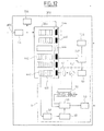
- FIG. 4 shows the elements of the telecommunications system of FIG. 1.
- the system comprises two telephone switching centers 14, 15, each center being connected on the one hand to a plurality of subscribers 16, 17 and on the other hand to a traffic station 12, 13 respectively.
- the centers switching provide frames at 2Mbits / s as shown in the Figure 2 and which will be detailed more precisely in Figure 6 in relation to the Figure 5.
- Each traffic station 12, 13 is connected to a device 26 for transmitting / receiving signals connected respectively to a satellite antenna 28, 29.
- FIG. 5 illustrates the arrangement of the device 26 within a cellular network infrastructure of the GSM type. It will be noted that the device 26 can be included in the BSC 22, or even be arranged on the A-ter interface.
- the device 26 is illustrated in more detail in Figure 6 '. he has a first input / output pair connected to the interface E1 connected to the BSC 22. This input / output couple is connected to a device 30 for compression / decompression of frames which will be detailed below. This device is also connected to a modem 31 intended to ensure transmission / reception in full-duplex time intervals, the transmission mode being TDMA. Modem 31 is connected to the input / output of a radio processing block 32 signal which is connected to the antenna 28, 29 respectively.
- the system also comprises, in a known manner, a management center resources 10, and a satellite 11 through which communications between the stations pass through.
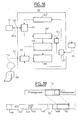
- a first input of the device 26 is connected to a first input of the first couple of the device 30 connected to an input of a device 301 of frame compression and providing an output signal to a first output from device 30 to modem 31 while a second input from device 30 connects the modem to a frame decompression device 302 of the device 30 delivering a signal of decompressed frames to an output of the device 26 to the BSC.
- the frame compression will be referred to as compressor while the decompression of frames will be called decompressor.
- the compressor 301 ensures the compression of the frames to be transmitted and adapting the format of the resulting data blocks to the interface offered by the modem 31 in transmission mode, namely an Ethernet, IP or ATM interface.
- the decompressor 302 ensures the adaptation to the interface offered by the modem 31 in reception mode (generally identical to that used on the transmission modem), as well as the restitution of the frames as applied in compressor input.
- FIG. 6 illustrates the typical structure of a frame 60 to be transmitted on the A-Bis or A-ter interface of cellular networks of the GSM type. Note that the present invention is not limited to such an interface and extends to any other type of interface, in particular those relating to non-cellular networks.
- Each frame is broken down into a fixed number of time intervals ("Time slot" in English), and in this case 32 time intervals for E1 frames in accordance with ITU-T recommendations G.703 / G.704, each time interval carrying a byte.
- the time interval referenced 0 is reserved for the synchronization of the transmission of the frames, with a view to synchronize the reception of the frames on the recipient equipment side.
- the frame frequency is 8 kHz, which allows to convey 31 channels at 64 kHz, one channel per interval.
- FIG. 7 illustrates the compressor 301 according to an embodiment of the invention of the lNV1 priority request.
- FIG. 7 shows the frame compression device 301 according to an embodiment of the invention of the priority request of INV1.
- the compression principle achieved by the compressor is as follows: the structure of the time interval being known, the compressor compares the content of the interval of the current frame relative to the content of this same interval on previous frames. This principle is shown schematically in Figure 8 where it is illustrated the principle of comparison for the reference time interval 2 and on a temporal length of 6 frames.
- Data frames enter via input 33 of compressor 301 which is connected to the input of the first input / output pair of the device 26.
- This input 33 is connected to a buffer memory 34 of frames ("buffer” in English) memorizing the current frame and operating according to FIFO logic (from English "First In First Out”).
- This buffer memory 34 is connected at the output to a entry of a memory 35 for storing the previous frame to the frame current present in memory 34.
- Memory 34 is also connected in output to an input of an analysis block 36, which input is connected in the block 36 to a block 361 for comparison. This block 361 is thus intended to compare the current frame with the previous frame to this one it receives on a second input connected to an output of the storage memory 35.
- Analysis block 36 also includes a block 362 for detecting state variations connected at input at the output of block 361 for comparison and a state machine 363 connected to the output of block 362 of detection and intended to determine the active or static states of each of the elements transmitted (for example the doublets transmitted), as it will be seen below.
- Memory 34 also outputs the current frame to the input of an extractor 37 of active elements, the latter being connected at the input to the output of state machine 363 from the analysis block.
- the state machine is connected in output in parallel with a status encoder 41 intended to supply codes compacts for identifying the position of the active elements, this being achieved by systematic way during operation or upon detection of a change of state of activity of the constituent elements of the frame.
- the memory 34 is connected in output at the input of a frame synchronization block 38 whose output is connected to the input of a frame counter 39.
- This counter 39 delivers a number specific to the current frame at a first entry of a grouping block 40 of data building blocks of data gathering own data to the current frame. The number provided by the counter 39 allows identification of the current frame.
- a second input of the grouping block 40 is connected at the output of extractor 37 while a third input is connected to the output of encoder 41.
- the grouping block 40 constructs a data block according to a method which will be detailed below and provides the latter as an output to a output buffer 42.
- a data block Preferably, several blocks are concatenated in this memory 42 before transmission to a physical output interface 43 of compressor 301 ensuring adaptation to the type of interface used for coupling with the transmission modem 31 (Ethernet, IP, or ATM).
- the compression process implemented by the compressor implements the following steps:
- the analysis block 36 analyzes the variations in content, based on the structure of the frame established by configuration in the case presented (by example doublet by doublet for a frame structured in doublets), and detects state variations. This is done within the analysis block by comparing in the comparison block each doublet with its corresponding doublet of at least the previous frame, the result being supplied to the detection block 362 which detects and provides activity states, active or static, to the machine 363, depending on whether the state of the doublet has varied or not.
- the state machine 363 transmits to block 40, via the status encoder 41, that the content of this doublet is no longer updated; the doublet is then considered to be in the static state.
- the compressor then stops the transmission of the doublet concerned.
- the codes which are transmitted to block 40 are representative of the variations state of the elements (in this case the doublets) and are a function of the structure of these elements. According to a convention (which can obviously be reversed or modified), a 1 indicates that an element is active, a 0 indicates that an element is static, within a chain of bits representing the state of the elements transmitted; for example, for a set of two consecutive time intervals each carrying four doublets, we could have the following combination of codes: 1010 1111 or AF in hexadecimal value. This suite is representative of six active doublets and two inactive doublets (those affected code 0). The indicator code for change of state is transmitted without delay, from that an element of the frame passes from the static state to the active state.
- the compressor has a pre-programmed state machine memory 3631 363 which has at least three frames (for example) to check the identity of the element considered on the three frames, but in addition the buffer memory 42 of the compressor keeps at least N frames compared to the indication of previous state change; this allows to space the signals of change of state and avoids overloading the link.
- the state machine is programmed to immediately transmit the frame change code.
- the frame change code includes all the status codes of the elements carried by the frame, only for the time intervals used, these status codes being developed according to the method defined above.
- the code 00AF issued by the encoder means that all the elements of the first time interval are static while those of the second time interval temporal are active except doublets 2 and 4 (example seen above 1010 1111).
- the state change code known as the state code below, serves as an indication of the location of the active elements of the frame.
- This status code is provided by the encoder 41 on the status information at the output of the machine state.
- the doublets can therefore have two stable exclusive states, respectively static or active, only are transmitted by the grouping block the doublets which have been signaled to it as active, by adding bits of padding to complete the data block according to the constraints of the interface used.
- These stuffing bits are managed by a manager 401 of internal padding bits in the grouping block. These stuffing bits will do explained in more detail below. Note that instead not useful stuffing information, it is possible to use this space of the frame to repeat critical data for the effective restitution of frames, such as the status code or frame number.
- FIG. 9 illustrates the structure of a data block 44 delivered by the block 40 for grouping the compressor.
- Block 44 includes a block 441 of compressed data including the doublets to be transmitted, a status code of the current frame, for example 00AF. This status code is representative of the position of the active elements within the frame considered.
- the compressor adds by encoder 41 or block 40, to the status code of the current frame, for example 00AF, a specific code 443 signaling the presence of a status code 442 within the block, which means that the transmitted data block corresponds to a state change case.
- the decompressor detects the addition of the status code by analyzing the length of the block data received. As soon as the block has a different length, the decompressor is able to deduce that a status code is present at the end of block.
- a frame number 444 is added at the head of the data block. compressed, intended to guarantee the synchronization of the decompression of taking into account cases of data block loss in the transmission channel.
- This frame number is counted modulo the capacity of the counter used for this purpose (8 bits or 16 bits for example).
- the data block thus formed is encapsulated in the frame Ethernet, IP packet, or ATM cell, depending on the transmission mode adopted.
- the buffer memory 42 Preferably, several blocks are concatenated in the buffer memory 42 before encapsulation to reduce the overhead associated with encapsulation.
- the output physical interface 43 ensures adaptation to the type of interface used for coupling with the transmission modem (Ethernet, IP, ATM).
- IP protocol over Ethernet allows to include optimized routing and rerouting functions automatic in the event of a link failure.
- the compressor being connected to a satellite transmission system which incorporates a DAMA function
- the allocation of satellite resources is done with a slow rhythm, for example every 1.6 seconds, while during these 1.6 seconds, a number of interlocutors will go from silence to speech and that over the same period, there are not necessarily as many that pass from the speech to silence, which explains the additional margin roughly equal to 50% between the allocation of channels by the system to the traffic station considered and the channels actually used on them.
- the allocation system of resources generally not allowing automatic consideration of a margin, the compressor adds margin bits intended to simulate a occupation of transmission resources in excess of its needs workforce. Additional bits not used for data transmission useful are used for the most critical information redundancy purposes by example, status code or frame number.
- a advantageous solution consists in multiplexing this redundant information on several consecutive data blocks, spacing the cyclic repetitions of this information by a repeating boundary indicator, and considering that the information thus multiplexed applies to the block carrying the repeat border.
- the role of the DAMA functionality being to ensure dynamic sharing of the band allocated according to the current needs of each station, in considering N stations with balanced current traffic, for the sake of simplification, with 16 communications on each station, we benefit from a gain considerable statistical multiplexing, if N is high enough (10 at least).
- N 1, the resources reserved for the 16 communications are strictly equal to the passage of 16 communications, i.e. 16 x 16 kbit / s (a communication requiring 16 kbits / s at the A-bis interface).
- N high greater than 10
- the ideal case is approximated, a case which corresponds to the theoretical sufficiency of the reservation of 50% of the total band for a station, i.e. 8 x 16 kbp / s per station, or for all 10 stations 10 x 8 x 16 kbps for a given direction, this quantity being to be doubled for both ways.
- the resource center artificially increases packet size transmitted by adding additional bits within each transmitted packet so as to have a sufficient margin of resources.
- the transmit modem used for transmission saturates, and rejects excess packets which it cannot transmit with regard to the capacity of transmission allocated to it for the current cycle.
- the repetition of the status code can be very relevant to the extent that the loss or poor reception of the status code by the receiving equipment could cause a disruption of the reconstruction of the frame, which would result in a shift of the doublets at the within the reconstructed frame.
- compression level 1 compression level 2 completes the first using a identical signaling, using a status code similar to the status code described for level 1. It operates by identifying the type of content conveyed by the transmission channel considered. Each communication is multiplexed temporally at the rate of a doublet for each frame, for a compressed channel at 16 kbps. This time multiplexing is itself structured in frames, by example of 320 bit frames every 20 ms. During the duration of a communication, an interlocutor is alternately active or silent. Of not specific to the device considered, during periods of silence, the frame transmission is maintained but an indicator within the frame indicates that this frame is not active.
- Level 2 compression uses this indicator to suspend the transmission of data relating to the compressed voice and to transmit only the useful elements of the frame of 320 bits.
- the bit corresponding to the position of the element considered in the input frame of the compression device is active within the level 2 status code, then as soon as this useful information has been transmitted, the bit is reset to the inactive state. This process increases the efficiency of the level 1 compression device by extending it by interpretation of non-static elements but containing data not useful.
- Figure 11 illustrates in detail a pressure relief device or decompressor 302 according to one embodiment of the invention of the application priority of INV1.
- An input connected to the reception modem 31 is connected to a 45 physical interface ensuring the adaptation of frames (Ethernet, IP, or ATM) to format of compressed data blocks according to the compression method exposed.
- frames Ethernet, IP, or ATM
- This interface 45 is connected at the output to the input of a buffer register 46 FIFO type storing the received data blocks.
- a first output from register 46 is linked to an extractor 47 of number 444 of frames while a second output is connected to an insertion means 48 active elements of the current frame and a third output from register 46 is it connected to a status code detector 49.
- a frame counter 50 internal to the decompressor is initialized at establishing the connection, with a negative offset to the number of the frame received. This provision is intended to prevent cases of famine due to a delay of the received frames with respect to the value of the counter.
- a comparator 501 compares the value of the frame number in extractor 47 and counter 50. When there is identity between the value of counter and the frame number associated with the block present in the buffer register 46, the comparator controls a memory 51 containing the previous frame to deliver it to an input of the insertion means 48.
- the status code detector 49 detects the status code associated with the block of data received, supplies it to the input of a status register 52 whose output is connected to another input of the insertion means 48.
- the memory register 46 delivers the block of data received to a third input of the insertion means 48. So on identity numbers frame and frame counter, the insertion means 48 reconstructs the frame current from the repetition of the previous frame of memory 51 and in replacing elements marked as active by the values contained in the block of data received, and on the basis of the information signaling the positions active elements delivered by the state register 52.
- the reconstructed frame is then delivered to a physical interface 53 ensuring the adaptation of the data blocks to the format of the frames conveyed on the A-bis interface.
- An example is the encapsulation of a user voice channel at 9.6 kbit / s in a 16 kbits frame, encapsulation carried out by adding bits of synchronization, stuffing and signaling.
- the compression method additional is intended to remove the synchronization and stuffing bits, and keep only the signaling bits (status codes, etc.) which have a dynamic character, in the sense given above by the detection of active elements.
- the synchronization of the restitution of original frames is carried out by implicitly, by detecting the border between the data blocks transmitted.
- the threshold is intended to avoid inadvertent switching of the mode compressed in uncompressed mode, especially when loading the frames at transmit is close to saturation.
- IBS Intelsat Business Services
- IBS framing transmission is very widespread, because it offers the possibility of transmitting N x 64 kbps, N being established as a function the real need of the network operator.
- IBS modems do not include functionality to dynamically vary the speed N x 64 kbps depending on the content to be transmitted.
- the tie-off compression device 30 traffic on two or more of its exits, each exit offering a fixed speed, activated according to the load resulting from compression by the compressor 301 according to the method described above.
- the compressed flow exceeds the reserved flow on the first channel, for example 5 x 64 kbits / s
- a part of the traffic on a second channel for example at 2 x 64 kbit / s
- this second channel is in turn saturated
- the original frames are reconstructed by concatenating the data blocks received via the main channel and via the additional channel.
- FIG. 12 illustrates a variant 303 of the decompression device 302 of Figure 11 which can also be applied advantageously in a any IP network, public or private.
- the advantageous functions in this case are: compressing / decompressing data at levels 1 and 2, adding frame number, decompression with resynchronization of output frames and specific treatment in case of non reception of the compressed frame at the instant it must be returned.
- the data blocks 44 enter the decompressor 303 by a input 3030.
- a frame number extractor 304 extracts the numbers of each frame making it possible to identify them.
- the blocks 44 are supplied to a memory (305) for storing the data blocks.
- Figure 12 are illustrated 6 data blocks characterized by their 444 frame numbers each represented by a solid block.
- the first box of each block represents the block code 442 and the following boxes correspond to compressed data 441.
- a broken line referenced A in FIG. 12 surrounds in particular the common part with FIG. 11 for the restitution of the original frames. This having already been described and explained, we will not return to it here.
- the device 303 comprises a circuit 307 for initializing counter receiving the number of the current frame as well as the number of data blocks stored in memory 305.
- circuit 307 initializes counter 50 by synchronizing it with the first frame number received by the decompressor.
- the decompressed frames are intended to be kept in the memory 305 of the recording device decompression as long as the frame number associated with them respectively is not identical to the frame number delivered by the local frame counter taking into account a negative offset, to allow a certain flexibility in the restitution of the frames and to compensate for the temporal fluctuations induced by the transmission system, which often happens during transmission by satellite or in terrestrial networks, in particular IP, while the frames are supposed to be returned at a constant and unchanging rate.
- the identity is produced at comparator 501, the frame for which the identity is appeared is then applied to the output of the decompression device.
- the previous frame is repeated and / or a code error is generated by a generator 307 for signaling the absence of frames to an unrepresented system management center telecommunications.
- the counter local frames are resynchronized on the frame identifiers received.
- the negative offset applied to the output of the frame counter is intended establish a margin to cover the range of time fluctuations induced by the satellite transmission system.
- Local counter initialization is performed according to statistics of variation of the number of blocks present in the buffer, by regulating the value minimum so that it is always greater than 1 taking into account a margin additional, and less than the buffer capacity expressed in number of maximum blocks.
- This decompression device therefore has the advantage of being able on the one hand to receive blocks of data in sequence disordered thanks to the memory 305, and on the other hand to be able to support transmission delay fluctuations thanks to the offset introduced.
- bit state is used during the N last frames preceding the current analysis window.
- the first two channels of the analysis window 70 repeats with a period of 4 consecutive frames, identical to the pattern of reference 71 constituted by the state of the channel during the last 4 frames preceding the current analysis window 70. A decision to repress the repeated pattern is then taken.
- the compression device 301 ′ according to the invention of lNV1, illustrated in FIG. 14, is similar to that 301 of FIG. 7, except for a memory 34 ′ for memorizing L * N current frames forming the window analysis 70 and a memory 35 'for storing the N frames preceding the analysis window forming the reference pattern.
- the device 302 ′ in FIG. 15 is similar to that of the Figure 11, except for the replacement of the memory 51 by a memory 51 ' for memorizing the reference pattern (the last 4 data frames preceding the current compressed frame).
- a problem can arise following a defect in serialization or sequencing resulting in an offset of the transmitted data, to right if channels declared inactive were inserted by mistake, left if channels declared active have not been inserted.
- FIG. 16 represents a structure 44 'of weft compressed according to the compression method of the invention of lNV1 from a set 500 of NT frames E1 and which feed back at the end of the chain, on the decompressor side, the NT E1 frames:
- This structure conventionally begins with at least one bit 446 of synchronization and ends with stuffing bits 447.
- the number of bits in the field 441 'says CAC is equal the number of bits at 1 in the status code, characterizing the position of the channels active within the input frame, multiplied by the NT number of incoming frames in the analysis window.
- the device compares the 8 bits of the received frame, located 80 bits after the end ACD CRC 445; if no formatting or transmission error has occurred produced, the field thus obtained is equal to the value established for a delimiter 448 arranged just after the ACC.
- the delimiter that fixes the border between the field "Concatenated active channels" and the stuffing bits can be offset from screw the position he is supposed to occupy.
- the delimiter has a fixed value, established on the side of the compressor, and equal to 1111 0000 for example.
- FIG. 18 represents a device 100 for multiplexing / demultiplexing data according to an embodiment of the invention.
- the device 100 comprises a first input / output 101 connected by an A-bis link to a BSC 22.
- a second input / output 102 connects the device 100 to the ethernet network 104 itself interconnected to a plurality of computers 103.
- the input / output 101 is connected in the device 100 to an interface E1 105.
- This delivers the E1 frames of traffic from the Abis link to a compressor 301 'as described above while on another of its inputs, the interface 105 receives E1 frames decompressed by a decompression performed by a decompressor 302 'as described above.
- the compressor outlet 301 ' is connected to a first input of a block 106 for formatting while the input of the decompressor is connected to a first output of a block 107 of déformattage.
- the functions of blocks 106 for formatting and 107 for deformatting will be explained below.
- the input / output 102 is connected in the device 100 to an ethernet port 108.
- This port 108 provides internet traffic (IP datagram flow) at the entrance of a buffer 109 for preventing short-term congestion.
- This memory 109 provides the datagrams to a second entry in block 106 of formatting.
- memory 109 makes it possible to prevent traffic congestion internet due to short-term variation in bandwidth margin available. The calculation of the available bandwidth is performed on a period of an analysis window.
- the size of the buffer memory 109 is dimensioned so as to be able to contain at least one IP datagram at the maximum size.
- the flow of internet traffic applied to memory 109 is controlled by based on available bandwidth prediction information provided by a bandwidth prediction block 110.
- This 110 predictor block operates from information supplied by compressor 301 ', information relating to the capacity available between each consecutive compressed frame. It will be noted that this prediction block can be a software means.
- this one receives compressed data from compressor 301 'and lP datagrams and formats the whole according to a determined format to route it to a input of a modem 111 to which an output of the device 100 is connected, for modulation / coding before transmission to a network satellite satellite telecommunications.
- the insertion of lP datagrams within the structure provided for the compressed data block requires to adapt the format of the Ethernet frames to the released E1 frames.
- Block 107 Conversely, the data blocks received by modem 111 in from the satellite are demodulated / decoded and then transmitted to an input of the device 100 connected to the deformatting block 107.
- Block 107 then has for function to unbundle the data blocks containing the data compressed Abis traffic from lP datagrams.
- the decompressed data are then directed to the decompressor 302 'while the datagrams lP are directed to port 108 ethernet.
- a mechanism for observing the state of activity of GSM channels also allow longer-term observation of the band condition available bandwidth.
- the bandwidth measurement and calculation period available is fixed so that the variation of the bandwidth available is low from one period to another.
- This mechanism makes it possible to predict the evolution of the available bandwidth and therefore avoid any congestion that may occur in subsequent periods.
- a margin is systematically added to bandwidth evolution forecasts used by compressed frames; this margin is lower the more the forecasts are reliable and the update period high in relation to the rhythm evolution of the band used.
- this margin can be very small; conversely, for type traffic data, the margin is generally large in order to cope with the variability significant flow to transmit.
- Figure 10 illustrates this process of forecasting the bandwidth used, with the addition of a margin, in order to know the remaining bandwidth available without risk of congestion of the multiplexing device of traffic received via the port ethernet.
- Available bandwidth forecasts are used to regulate the flow applied at the input of the traffic multiplexing device, materialized by the buffer memory 109 and the formatting block 106.
- This flow regulation operates conventionally through a TCP type protocol by not acknowledgment or negative acknowledgment of received packets, imposing on the source to repeat a sending attempt generally made with a size of weaker packet, or by explicit provision of source information intended to perform this flow regulation, relevant case especially when the exchange information is not operated using the TCP protocol.
- Flow regulation is essential, as it avoids to clutter the buffer memory 109 with data packets which are not can guarantee all-wheel drive within a fixed period.
- This principle allows automatically adjust the size and rate of the packets applied via the Ethernet network at the capacity available at the multiplexing device.
- predictions of available bandwidth can be used to adjust the discard thresholds for packets arriving in the buffer against short-term congestion.
- FIG. 20 represents a device 113 for demultiplexing at the level of the remote receiver terminal.
- IP datagrams are reconstructed as they were originally by extraction of the sections present at the end of 44 "data blocks compressed and by concatenation of these and based on the delimitations specific to IP datagrams to render each datagram in its original form.
- internet traffic is directed to the LAN or WLAN network to which the user terminal is connected.
- the device according to the invention offers the advantage of being able to upgrade low cost (no impact on the radio part) of backhaul satellite links to allow a LAN or WLAN connection and carry traffic Internet in parallel with the signaling and traffic of the Abis interface.
- the device can also allow Internet traffic to flow with a quality of service requirement, by providing a bandwidth margin compared to the bandwidth sizing provided for traffic the mobile network interface.
- the device can be applied to transmission solutions to allow mutualisation of the transmission transmission line of base station with transmission line of LAN connection or WLAN.
- the invention is not limited to lP datagrams, any type of data flow can be inserted in the same way instead and place stuffing bits, and be recovered during decompression.
Landscapes
- Engineering & Computer Science (AREA)
- Computer Networks & Wireless Communication (AREA)
- Signal Processing (AREA)
- Computer Security & Cryptography (AREA)
- Physics & Mathematics (AREA)
- Astronomy & Astrophysics (AREA)
- Aviation & Aerospace Engineering (AREA)
- General Physics & Mathematics (AREA)
- Time-Division Multiplex Systems (AREA)
- Data Exchanges In Wide-Area Networks (AREA)
- Radio Relay Systems (AREA)
- Mobile Radio Communication Systems (AREA)
Applications Claiming Priority (2)
| Application Number | Priority Date | Filing Date | Title |
|---|---|---|---|
| FR0209263A FR2842683B1 (fr) | 2002-07-22 | 2002-07-22 | Dispositif de multiplexage, dispositif de multiplexage et systeme de multiplexage/demultiplexage |
| FR0209263 | 2002-07-22 |
Publications (2)
| Publication Number | Publication Date |
|---|---|
| EP1385315A2 true EP1385315A2 (de) | 2004-01-28 |
| EP1385315A3 EP1385315A3 (de) | 2010-07-14 |
Family
ID=29797621
Family Applications (1)
| Application Number | Title | Priority Date | Filing Date |
|---|---|---|---|
| EP03291730A Withdrawn EP1385315A3 (de) | 2002-07-22 | 2003-07-11 | Multiplexvorrichtung, Demultiplexvorrichtung und Multiplex/Demultiplexsystem |
Country Status (3)
| Country | Link |
|---|---|
| US (1) | US7623554B2 (de) |
| EP (1) | EP1385315A3 (de) |
| FR (1) | FR2842683B1 (de) |
Families Citing this family (19)
| Publication number | Priority date | Publication date | Assignee | Title |
|---|---|---|---|---|
| FR2841726B1 (fr) * | 2002-06-28 | 2005-04-29 | Cit Alcatel | Methode de decision securisee d'un etat de donnee d'un canal de communication pour systeme de transmission |
| US7564792B2 (en) * | 2003-11-05 | 2009-07-21 | Juniper Networks, Inc. | Transparent optimization for transmission control protocol flow control |
| US7457315B1 (en) * | 2003-12-23 | 2008-11-25 | Cisco Technology, Inc. | System and method for compressing information in a communications environment |
| US7558289B1 (en) * | 2004-06-17 | 2009-07-07 | Marvell International Ltd. | Method and apparatus for providing quality of service (QOS) in a wireless local area network |
| US7571246B2 (en) | 2004-07-29 | 2009-08-04 | Microsoft Corporation | Media transrating over a bandwidth-limited network |
| US7924731B2 (en) * | 2004-11-15 | 2011-04-12 | Telefonaktiebolaget Lm Ericsson (Publ) | Method and apparatus for handling out-of-sequence packets in header decompression |
| US7743183B2 (en) * | 2005-05-23 | 2010-06-22 | Microsoft Corporation | Flow control for media streaming |
| US8804765B2 (en) * | 2005-06-21 | 2014-08-12 | Optis Wireless Technology, Llc | Dynamic robust header compression |
| GB0522987D0 (en) * | 2005-11-10 | 2005-12-21 | Cambridge Broadband Ltd | Communication system |
| US20080056194A1 (en) * | 2006-08-29 | 2008-03-06 | Gonorovsky Ilya O | System for combining uplink data blocks from a user with transmission pauses from another user |
| US20080058004A1 (en) * | 2006-08-29 | 2008-03-06 | Motorola, Inc. | System and method for reassigning an uplink time slot from a circuit-switched gprs mobile device to a different packet-switched gprs mobile device |
| JP2010081182A (ja) * | 2008-09-25 | 2010-04-08 | Renesas Technology Corp | 画像処理装置 |
| US8171157B2 (en) * | 2009-12-21 | 2012-05-01 | Microsoft Corporation | Distributing bandwidth across communication modalities |
| US8441930B2 (en) * | 2009-12-21 | 2013-05-14 | Microsoft Corporation | Estimating communication conditions |
| JP5784707B2 (ja) * | 2010-05-03 | 2015-09-24 | ケイ ティー コーポレイションKt Corporation | 多様な類型の通信信号を統合中継する統合中継機及び統合中継システム |
| GB2483282B (en) * | 2010-09-03 | 2017-09-13 | Advanced Risc Mach Ltd | Data compression and decompression using relative and absolute delta values |
| IL219839A0 (en) * | 2012-05-16 | 2012-08-30 | Elbit Systems Land & C4I Ltd | Bandwidth prediction for cellular backhauling |
| CN103260053B (zh) * | 2013-04-15 | 2016-12-28 | 威盛电子股份有限公司 | 动态调整多媒体数据码率的系统、媒体播放装置及方法 |
| CN109617834B (zh) * | 2019-02-01 | 2021-08-24 | 国网江苏省电力有限公司 | 一种精准切负荷系统及其通信方法、接入装置 |
Family Cites Families (11)
| Publication number | Priority date | Publication date | Assignee | Title |
|---|---|---|---|---|
| US4962497A (en) * | 1989-09-21 | 1990-10-09 | At&T Bell Laboratories | Building-block architecture of a multi-node circuit-and packet-switching system |
| FI940093A0 (fi) * | 1994-01-10 | 1994-01-10 | Nokia Mobile Phones Ltd | Foerfarande foer oeverfoering av data och datagraenssnittenhet |
| US20020009060A1 (en) * | 2000-05-05 | 2002-01-24 | Todd Gross | Satellite transceiver card for bandwidth on demand applications |
| US20020038373A1 (en) * | 2000-07-21 | 2002-03-28 | John Border | Method and system for improving network performance enhancing proxy architecture with gateway redundancy |
| AU5596301A (en) * | 2000-08-09 | 2002-02-14 | Alcatel | Method and system for transmitting IP traffic in a radiocommunication system |
| US20020116707A1 (en) * | 2000-12-11 | 2002-08-22 | Morris Richard M. | Streaming media client system and method |
| US6721282B2 (en) * | 2001-01-12 | 2004-04-13 | Telecompression Technologies, Inc. | Telecommunication data compression apparatus and method |
| FR2819674B1 (fr) * | 2001-01-15 | 2003-05-23 | Cit Alcatel | Dispositif de transmission comportant une memoire de masse pour stockage temporaire de flux d'informations a temps differe |
| US6947446B2 (en) * | 2001-01-16 | 2005-09-20 | Motorola, Inc. | Slot format and acknowledgement method for a wireless communication system |
| WO2002078365A1 (en) * | 2001-03-21 | 2002-10-03 | Pelago Networks, Inc. | Programmable network service node |
| US7106738B2 (en) * | 2001-04-06 | 2006-09-12 | Erlang Technologies, Inc. | Method and apparatus for high speed packet switching using train packet queuing and providing high scalability |
-
2002
- 2002-07-22 FR FR0209263A patent/FR2842683B1/fr not_active Expired - Fee Related
-
2003
- 2003-07-11 EP EP03291730A patent/EP1385315A3/de not_active Withdrawn
- 2003-07-21 US US10/622,550 patent/US7623554B2/en not_active Expired - Fee Related
Also Published As
| Publication number | Publication date |
|---|---|
| US7623554B2 (en) | 2009-11-24 |
| FR2842683B1 (fr) | 2005-01-14 |
| US20050100056A1 (en) | 2005-05-12 |
| EP1385315A3 (de) | 2010-07-14 |
| FR2842683A1 (fr) | 2004-01-23 |
Similar Documents
| Publication | Publication Date | Title |
|---|---|---|
| EP1385315A2 (de) | Multiplexvorrichtung, Demultiplexvorrichtung und Multiplex/Demultiplexsystem | |
| EP0104991B1 (de) | Lokales hybrides Nachrichtennetz in Durchschalte- und Paketvermittlungsbetrieb mit einer Zeitmultiplex-Ringleitung | |
| EP0036808B1 (de) | Konzentrator für Kommunikationssystem zum Anschliessen mehrerer asynchroner Telematik-Terminals | |
| EP1421723B1 (de) | Kompressor, dekompressor und ressourcenverwaltungsverfahren | |
| EP0162173A1 (de) | Digitales Übertragungssystem für Sprachpakete | |
| FR2669798A1 (fr) | Dispositif pour la transmission d'informations synchrones par un reseau asynchrone, notamment un reseau atm. | |
| FR2526615A1 (fr) | Coupleur a haut debit entre un multiplex de voies mic et un commutateur de paquets | |
| FR2570234A1 (fr) | Procede de transmission de donnees par interface et dispositif de liaison par interface pour la mise en oeuvre de ce procede | |
| FR2582464A1 (fr) | Systeme de transmission d'information du type a boucle fermee | |
| CA2006832C (fr) | Systeme de reception et de traitement de trames hdlc transmises sur liaison mic multivoies a multiplexage temporel, notamment pour commutateur de donnees | |
| EP1545140B1 (de) | Schicht-ZweiI Kompression/Dekompression in einem zellularen Kommunikationsnetz | |
| EP0987917A1 (de) | Verfahren zur Zellulären Datenkommunikation, Zell, Kommunikationssystem und Netz-Endgerät | |
| EP1478195A1 (de) | Betriebsmittelverwaltung in einem Punkt zu Mehrpunkt oder Mehrpunkt zu Mehrpunkt Kommunikationsnetzwerk, mit zwei Zuteilungsebenen | |
| EP0374028B1 (de) | Kommunikationssystem und Verfahren mit Informationsverschlüsselung | |
| FR2833118A1 (fr) | Procede d'estimation de performance lors de la fourniture de services de donnees intolerants vis-a vis des retards | |
| EP1376958B1 (de) | Verfahren zur sicheren Entscheidung eines gegebenen Zustandes von einem Kommunikationskanal für ein Übertragungssystem | |
| FR2711466A1 (fr) | Appareil de test de réseau de télécommunication de type ATM et de mesure de performance de connexion ATM. | |
| EP2206331B1 (de) | Umkonfiguration von netzwerkabschlusseinrichtungen | |
| WO2023156580A1 (fr) | Procédés et dispositifs de traitement de données descendantes pour réseaux optique passifs en cascade | |
| FR2691029A1 (fr) | Procédé d'analyse à distance de données d'un protocole, terminal d'abonné spécialisé et dispositif d'analyse distant correspondant. | |
| EP1972110A1 (de) | Implizite reservierung von ressourcen in einem punkt-zu-multipunkt- oder multipunkt-zu-multipunkt-kommunikationsnetzwerk | |
| EP2507948A1 (de) | Vorrichtung und verfahren zur aggregation von über mehrere physische verbindungen empfangenen daten | |
| FR2900530A1 (fr) | Dispositif de routage local de trafics locaux au sein d'un reseau de communitation radio, par detection dans des copies de trames descendantes de donnees correspondant a des copies de trames montantes | |
| WO2023156579A1 (fr) | Procédés et dispositifs de traitement de données montantes pour réseaux optiques passifs en cascade | |
| EP1244329A1 (de) | Verfahren und Vorrichtung zur Übertragung von Daten innerhalb eines eine Übertragungsleitung mit niedriger Datenrate enthaltenden Kommunikationsnetzes |
Legal Events
| Date | Code | Title | Description |
|---|---|---|---|
| PUAI | Public reference made under article 153(3) epc to a published international application that has entered the european phase |
Free format text: ORIGINAL CODE: 0009012 |
|
| AK | Designated contracting states |
Kind code of ref document: A2 Designated state(s): AT BE BG CH CY CZ DE DK EE ES FI FR GB GR HU IE IT LI LU MC NL PT RO SE SI SK TR |
|
| AX | Request for extension of the european patent |
Extension state: AL LT LV MK |
|
| RAP1 | Party data changed (applicant data changed or rights of an application transferred) |
Owner name: ALCATEL LUCENT |
|
| PUAL | Search report despatched |
Free format text: ORIGINAL CODE: 0009013 |
|
| AK | Designated contracting states |
Kind code of ref document: A3 Designated state(s): AT BE BG CH CY CZ DE DK EE ES FI FR GB GR HU IE IT LI LU MC NL PT RO SE SI SK TR |
|
| AX | Request for extension of the european patent |
Extension state: AL LT LV MK |
|
| RIC1 | Information provided on ipc code assigned before grant |
Ipc: H04L 12/56 20060101ALI20100604BHEP Ipc: H04B 7/185 20060101AFI20100604BHEP |
|
| 17P | Request for examination filed |
Effective date: 20110114 |
|
| AKX | Designation fees paid |
Designated state(s): AT BE BG CH CY CZ DE DK EE ES FI FR GB GR HU IE IT LI LU MC NL PT RO SE SI SK TR |
|
| 17Q | First examination report despatched |
Effective date: 20110224 |
|
| STAA | Information on the status of an ep patent application or granted ep patent |
Free format text: STATUS: THE APPLICATION IS DEEMED TO BE WITHDRAWN |
|
| 18D | Application deemed to be withdrawn |
Effective date: 20110707 |