EP1386802A1 - A method for detecting a roll rate sensor fault - Google Patents
A method for detecting a roll rate sensor fault Download PDFInfo
- Publication number
- EP1386802A1 EP1386802A1 EP03254788A EP03254788A EP1386802A1 EP 1386802 A1 EP1386802 A1 EP 1386802A1 EP 03254788 A EP03254788 A EP 03254788A EP 03254788 A EP03254788 A EP 03254788A EP 1386802 A1 EP1386802 A1 EP 1386802A1
- Authority
- EP
- European Patent Office
- Prior art keywords
- rate sensor
- roll
- roll rate
- signal
- recited
- Prior art date
- Legal status (The legal status is an assumption and is not a legal conclusion. Google has not performed a legal analysis and makes no representation as to the accuracy of the status listed.)
- Granted
Links
Images


Classifications
-
- B—PERFORMING OPERATIONS; TRANSPORTING
- B60—VEHICLES IN GENERAL
- B60T—VEHICLE BRAKE CONTROL SYSTEMS OR PARTS THEREOF; BRAKE CONTROL SYSTEMS OR PARTS THEREOF, IN GENERAL; ARRANGEMENT OF BRAKING ELEMENTS ON VEHICLES IN GENERAL; PORTABLE DEVICES FOR PREVENTING UNWANTED MOVEMENT OF VEHICLES; VEHICLE MODIFICATIONS TO FACILITATE COOLING OF BRAKES
- B60T8/00—Arrangements for adjusting wheel-braking force to meet varying vehicular or ground-surface conditions, e.g. limiting or varying distribution of braking force
- B60T8/17—Using electrical or electronic regulation means to control braking
- B60T8/1755—Brake regulation specially adapted to control the stability of the vehicle, e.g. taking into account yaw rate or transverse acceleration in a curve
-
- B—PERFORMING OPERATIONS; TRANSPORTING
- B60—VEHICLES IN GENERAL
- B60G—VEHICLE SUSPENSION ARRANGEMENTS
- B60G17/00—Resilient suspensions having means for adjusting the spring or vibration-damper characteristics, for regulating the distance between a supporting surface and a sprung part of vehicle or for locking suspension during use to meet varying vehicular or surface conditions, e.g. due to speed or load
- B60G17/015—Resilient suspensions having means for adjusting the spring or vibration-damper characteristics, for regulating the distance between a supporting surface and a sprung part of vehicle or for locking suspension during use to meet varying vehicular or surface conditions, e.g. due to speed or load the regulating means comprising electric or electronic elements
- B60G17/016—Resilient suspensions having means for adjusting the spring or vibration-damper characteristics, for regulating the distance between a supporting surface and a sprung part of vehicle or for locking suspension during use to meet varying vehicular or surface conditions, e.g. due to speed or load the regulating means comprising electric or electronic elements characterised by their responsiveness, when the vehicle is travelling, to specific motion, a specific condition, or driver input
- B60G17/0162—Resilient suspensions having means for adjusting the spring or vibration-damper characteristics, for regulating the distance between a supporting surface and a sprung part of vehicle or for locking suspension during use to meet varying vehicular or surface conditions, e.g. due to speed or load the regulating means comprising electric or electronic elements characterised by their responsiveness, when the vehicle is travelling, to specific motion, a specific condition, or driver input mainly during a motion involving steering operation, e.g. cornering, overtaking
-
- B—PERFORMING OPERATIONS; TRANSPORTING
- B60—VEHICLES IN GENERAL
- B60G—VEHICLE SUSPENSION ARRANGEMENTS
- B60G17/00—Resilient suspensions having means for adjusting the spring or vibration-damper characteristics, for regulating the distance between a supporting surface and a sprung part of vehicle or for locking suspension during use to meet varying vehicular or surface conditions, e.g. due to speed or load
- B60G17/015—Resilient suspensions having means for adjusting the spring or vibration-damper characteristics, for regulating the distance between a supporting surface and a sprung part of vehicle or for locking suspension during use to meet varying vehicular or surface conditions, e.g. due to speed or load the regulating means comprising electric or electronic elements
- B60G17/018—Resilient suspensions having means for adjusting the spring or vibration-damper characteristics, for regulating the distance between a supporting surface and a sprung part of vehicle or for locking suspension during use to meet varying vehicular or surface conditions, e.g. due to speed or load the regulating means comprising electric or electronic elements characterised by the use of a specific signal treatment or control method
- B60G17/0182—Resilient suspensions having means for adjusting the spring or vibration-damper characteristics, for regulating the distance between a supporting surface and a sprung part of vehicle or for locking suspension during use to meet varying vehicular or surface conditions, e.g. due to speed or load the regulating means comprising electric or electronic elements characterised by the use of a specific signal treatment or control method involving parameter estimation, e.g. observer, Kalman filter
-
- B—PERFORMING OPERATIONS; TRANSPORTING
- B60—VEHICLES IN GENERAL
- B60G—VEHICLE SUSPENSION ARRANGEMENTS
- B60G17/00—Resilient suspensions having means for adjusting the spring or vibration-damper characteristics, for regulating the distance between a supporting surface and a sprung part of vehicle or for locking suspension during use to meet varying vehicular or surface conditions, e.g. due to speed or load
- B60G17/015—Resilient suspensions having means for adjusting the spring or vibration-damper characteristics, for regulating the distance between a supporting surface and a sprung part of vehicle or for locking suspension during use to meet varying vehicular or surface conditions, e.g. due to speed or load the regulating means comprising electric or electronic elements
- B60G17/018—Resilient suspensions having means for adjusting the spring or vibration-damper characteristics, for regulating the distance between a supporting surface and a sprung part of vehicle or for locking suspension during use to meet varying vehicular or surface conditions, e.g. due to speed or load the regulating means comprising electric or electronic elements characterised by the use of a specific signal treatment or control method
- B60G17/0185—Resilient suspensions having means for adjusting the spring or vibration-damper characteristics, for regulating the distance between a supporting surface and a sprung part of vehicle or for locking suspension during use to meet varying vehicular or surface conditions, e.g. due to speed or load the regulating means comprising electric or electronic elements characterised by the use of a specific signal treatment or control method for failure detection
-
- B—PERFORMING OPERATIONS; TRANSPORTING
- B60—VEHICLES IN GENERAL
- B60G—VEHICLE SUSPENSION ARRANGEMENTS
- B60G17/00—Resilient suspensions having means for adjusting the spring or vibration-damper characteristics, for regulating the distance between a supporting surface and a sprung part of vehicle or for locking suspension during use to meet varying vehicular or surface conditions, e.g. due to speed or load
- B60G17/015—Resilient suspensions having means for adjusting the spring or vibration-damper characteristics, for regulating the distance between a supporting surface and a sprung part of vehicle or for locking suspension during use to meet varying vehicular or surface conditions, e.g. due to speed or load the regulating means comprising electric or electronic elements
- B60G17/0195—Resilient suspensions having means for adjusting the spring or vibration-damper characteristics, for regulating the distance between a supporting surface and a sprung part of vehicle or for locking suspension during use to meet varying vehicular or surface conditions, e.g. due to speed or load the regulating means comprising electric or electronic elements characterised by the regulation being combined with other vehicle control systems
-
- B—PERFORMING OPERATIONS; TRANSPORTING
- B60—VEHICLES IN GENERAL
- B60R—VEHICLES, VEHICLE FITTINGS, OR VEHICLE PARTS, NOT OTHERWISE PROVIDED FOR
- B60R16/00—Electric or fluid circuits specially adapted for vehicles and not otherwise provided for; Arrangement of elements of electric or fluid circuits specially adapted for vehicles and not otherwise provided for
- B60R16/02—Electric or fluid circuits specially adapted for vehicles and not otherwise provided for; Arrangement of elements of electric or fluid circuits specially adapted for vehicles and not otherwise provided for electric constitutive elements
- B60R16/023—Electric or fluid circuits specially adapted for vehicles and not otherwise provided for; Arrangement of elements of electric or fluid circuits specially adapted for vehicles and not otherwise provided for electric constitutive elements for transmission of signals between vehicle parts or subsystems
- B60R16/0231—Circuits relating to the driving or the functioning of the vehicle
- B60R16/0232—Circuits relating to the driving or the functioning of the vehicle for measuring vehicle parameters and indicating critical, abnormal or dangerous conditions
- B60R16/0233—Vehicle tilting, overturning or roll over
-
- B—PERFORMING OPERATIONS; TRANSPORTING
- B60—VEHICLES IN GENERAL
- B60R—VEHICLES, VEHICLE FITTINGS, OR VEHICLE PARTS, NOT OTHERWISE PROVIDED FOR
- B60R21/00—Arrangements or fittings on vehicles for protecting or preventing injuries to occupants or pedestrians in case of accidents or other traffic risks
- B60R21/01—Electrical circuits for triggering passive safety arrangements, e.g. airbags, safety belt tighteners, in case of vehicle accidents or impending vehicle accidents
-
- B—PERFORMING OPERATIONS; TRANSPORTING
- B60—VEHICLES IN GENERAL
- B60R—VEHICLES, VEHICLE FITTINGS, OR VEHICLE PARTS, NOT OTHERWISE PROVIDED FOR
- B60R21/00—Arrangements or fittings on vehicles for protecting or preventing injuries to occupants or pedestrians in case of accidents or other traffic risks
- B60R21/01—Electrical circuits for triggering passive safety arrangements, e.g. airbags, safety belt tighteners, in case of vehicle accidents or impending vehicle accidents
- B60R21/013—Electrical circuits for triggering passive safety arrangements, e.g. airbags, safety belt tighteners, in case of vehicle accidents or impending vehicle accidents including means for detecting collisions, impending collisions or roll-over
-
- B—PERFORMING OPERATIONS; TRANSPORTING
- B60—VEHICLES IN GENERAL
- B60R—VEHICLES, VEHICLE FITTINGS, OR VEHICLE PARTS, NOT OTHERWISE PROVIDED FOR
- B60R21/00—Arrangements or fittings on vehicles for protecting or preventing injuries to occupants or pedestrians in case of accidents or other traffic risks
- B60R21/01—Electrical circuits for triggering passive safety arrangements, e.g. airbags, safety belt tighteners, in case of vehicle accidents or impending vehicle accidents
- B60R21/013—Electrical circuits for triggering passive safety arrangements, e.g. airbags, safety belt tighteners, in case of vehicle accidents or impending vehicle accidents including means for detecting collisions, impending collisions or roll-over
- B60R21/0132—Electrical circuits for triggering passive safety arrangements, e.g. airbags, safety belt tighteners, in case of vehicle accidents or impending vehicle accidents including means for detecting collisions, impending collisions or roll-over responsive to vehicle motion parameters, e.g. to vehicle longitudinal or transversal deceleration or speed value
-
- B—PERFORMING OPERATIONS; TRANSPORTING
- B60—VEHICLES IN GENERAL
- B60T—VEHICLE BRAKE CONTROL SYSTEMS OR PARTS THEREOF; BRAKE CONTROL SYSTEMS OR PARTS THEREOF, IN GENERAL; ARRANGEMENT OF BRAKING ELEMENTS ON VEHICLES IN GENERAL; PORTABLE DEVICES FOR PREVENTING UNWANTED MOVEMENT OF VEHICLES; VEHICLE MODIFICATIONS TO FACILITATE COOLING OF BRAKES
- B60T17/00—Component parts, details, or accessories of power brake systems not covered by groups B60T8/00, B60T13/00 or B60T15/00, or presenting other characteristic features
- B60T17/18—Safety devices; Monitoring
- B60T17/22—Devices for monitoring or checking brake systems; Signal devices
-
- B—PERFORMING OPERATIONS; TRANSPORTING
- B60—VEHICLES IN GENERAL
- B60T—VEHICLE BRAKE CONTROL SYSTEMS OR PARTS THEREOF; BRAKE CONTROL SYSTEMS OR PARTS THEREOF, IN GENERAL; ARRANGEMENT OF BRAKING ELEMENTS ON VEHICLES IN GENERAL; PORTABLE DEVICES FOR PREVENTING UNWANTED MOVEMENT OF VEHICLES; VEHICLE MODIFICATIONS TO FACILITATE COOLING OF BRAKES
- B60T8/00—Arrangements for adjusting wheel-braking force to meet varying vehicular or ground-surface conditions, e.g. limiting or varying distribution of braking force
-
- B—PERFORMING OPERATIONS; TRANSPORTING
- B60—VEHICLES IN GENERAL
- B60T—VEHICLE BRAKE CONTROL SYSTEMS OR PARTS THEREOF; BRAKE CONTROL SYSTEMS OR PARTS THEREOF, IN GENERAL; ARRANGEMENT OF BRAKING ELEMENTS ON VEHICLES IN GENERAL; PORTABLE DEVICES FOR PREVENTING UNWANTED MOVEMENT OF VEHICLES; VEHICLE MODIFICATIONS TO FACILITATE COOLING OF BRAKES
- B60T8/00—Arrangements for adjusting wheel-braking force to meet varying vehicular or ground-surface conditions, e.g. limiting or varying distribution of braking force
- B60T8/17—Using electrical or electronic regulation means to control braking
- B60T8/172—Determining control parameters used in the regulation, e.g. by calculations involving measured or detected parameters
-
- B—PERFORMING OPERATIONS; TRANSPORTING
- B60—VEHICLES IN GENERAL
- B60T—VEHICLE BRAKE CONTROL SYSTEMS OR PARTS THEREOF; BRAKE CONTROL SYSTEMS OR PARTS THEREOF, IN GENERAL; ARRANGEMENT OF BRAKING ELEMENTS ON VEHICLES IN GENERAL; PORTABLE DEVICES FOR PREVENTING UNWANTED MOVEMENT OF VEHICLES; VEHICLE MODIFICATIONS TO FACILITATE COOLING OF BRAKES
- B60T8/00—Arrangements for adjusting wheel-braking force to meet varying vehicular or ground-surface conditions, e.g. limiting or varying distribution of braking force
- B60T8/24—Arrangements for adjusting wheel-braking force to meet varying vehicular or ground-surface conditions, e.g. limiting or varying distribution of braking force responsive to vehicle inclination or change of direction, e.g. negotiating bends
- B60T8/241—Lateral vehicle inclination
-
- B—PERFORMING OPERATIONS; TRANSPORTING
- B60—VEHICLES IN GENERAL
- B60T—VEHICLE BRAKE CONTROL SYSTEMS OR PARTS THEREOF; BRAKE CONTROL SYSTEMS OR PARTS THEREOF, IN GENERAL; ARRANGEMENT OF BRAKING ELEMENTS ON VEHICLES IN GENERAL; PORTABLE DEVICES FOR PREVENTING UNWANTED MOVEMENT OF VEHICLES; VEHICLE MODIFICATIONS TO FACILITATE COOLING OF BRAKES
- B60T8/00—Arrangements for adjusting wheel-braking force to meet varying vehicular or ground-surface conditions, e.g. limiting or varying distribution of braking force
- B60T8/24—Arrangements for adjusting wheel-braking force to meet varying vehicular or ground-surface conditions, e.g. limiting or varying distribution of braking force responsive to vehicle inclination or change of direction, e.g. negotiating bends
- B60T8/241—Lateral vehicle inclination
- B60T8/243—Lateral vehicle inclination for roll-over protection
-
- B—PERFORMING OPERATIONS; TRANSPORTING
- B60—VEHICLES IN GENERAL
- B60T—VEHICLE BRAKE CONTROL SYSTEMS OR PARTS THEREOF; BRAKE CONTROL SYSTEMS OR PARTS THEREOF, IN GENERAL; ARRANGEMENT OF BRAKING ELEMENTS ON VEHICLES IN GENERAL; PORTABLE DEVICES FOR PREVENTING UNWANTED MOVEMENT OF VEHICLES; VEHICLE MODIFICATIONS TO FACILITATE COOLING OF BRAKES
- B60T8/00—Arrangements for adjusting wheel-braking force to meet varying vehicular or ground-surface conditions, e.g. limiting or varying distribution of braking force
- B60T8/32—Arrangements for adjusting wheel-braking force to meet varying vehicular or ground-surface conditions, e.g. limiting or varying distribution of braking force responsive to a speed condition, e.g. acceleration or deceleration
- B60T8/88—Arrangements for adjusting wheel-braking force to meet varying vehicular or ground-surface conditions, e.g. limiting or varying distribution of braking force responsive to a speed condition, e.g. acceleration or deceleration with failure responsive means, i.e. means for detecting and indicating faulty operation of the speed responsive control means
- B60T8/885—Arrangements for adjusting wheel-braking force to meet varying vehicular or ground-surface conditions, e.g. limiting or varying distribution of braking force responsive to a speed condition, e.g. acceleration or deceleration with failure responsive means, i.e. means for detecting and indicating faulty operation of the speed responsive control means using electrical circuitry
-
- B—PERFORMING OPERATIONS; TRANSPORTING
- B60—VEHICLES IN GENERAL
- B60G—VEHICLE SUSPENSION ARRANGEMENTS
- B60G2600/00—Indexing codes relating to particular elements, systems or processes used on suspension systems or suspension control systems
- B60G2600/08—Failure or malfunction detecting means
-
- B—PERFORMING OPERATIONS; TRANSPORTING
- B60—VEHICLES IN GENERAL
- B60G—VEHICLE SUSPENSION ARRANGEMENTS
- B60G2600/00—Indexing codes relating to particular elements, systems or processes used on suspension systems or suspension control systems
- B60G2600/18—Automatic control means
- B60G2600/187—Digital Controller Details and Signal Treatment
- B60G2600/1871—Optimal control; Kalman Filters
-
- B—PERFORMING OPERATIONS; TRANSPORTING
- B60—VEHICLES IN GENERAL
- B60G—VEHICLE SUSPENSION ARRANGEMENTS
- B60G2800/00—Indexing codes relating to the type of movement or to the condition of the vehicle and to the end result to be achieved by the control action
- B60G2800/01—Attitude or posture control
- B60G2800/019—Inclination due to load distribution or road gradient
- B60G2800/0194—Inclination due to load distribution or road gradient transversal with regard to vehicle
-
- B—PERFORMING OPERATIONS; TRANSPORTING
- B60—VEHICLES IN GENERAL
- B60G—VEHICLE SUSPENSION ARRANGEMENTS
- B60G2800/00—Indexing codes relating to the type of movement or to the condition of the vehicle and to the end result to be achieved by the control action
- B60G2800/21—Traction, slip, skid or slide control
- B60G2800/215—Traction, slip, skid or slide control by applying a braking action on each wheel individually
-
- B—PERFORMING OPERATIONS; TRANSPORTING
- B60—VEHICLES IN GENERAL
- B60G—VEHICLE SUSPENSION ARRANGEMENTS
- B60G2800/00—Indexing codes relating to the type of movement or to the condition of the vehicle and to the end result to be achieved by the control action
- B60G2800/80—Detection or control after a system or component failure
-
- B—PERFORMING OPERATIONS; TRANSPORTING
- B60—VEHICLES IN GENERAL
- B60G—VEHICLE SUSPENSION ARRANGEMENTS
- B60G2800/00—Indexing codes relating to the type of movement or to the condition of the vehicle and to the end result to be achieved by the control action
- B60G2800/90—System Controller type
- B60G2800/92—ABS - Brake Control
- B60G2800/922—EBV - Electronic brake force distribution
-
- B—PERFORMING OPERATIONS; TRANSPORTING
- B60—VEHICLES IN GENERAL
- B60R—VEHICLES, VEHICLE FITTINGS, OR VEHICLE PARTS, NOT OTHERWISE PROVIDED FOR
- B60R21/00—Arrangements or fittings on vehicles for protecting or preventing injuries to occupants or pedestrians in case of accidents or other traffic risks
- B60R2021/0002—Type of accident
- B60R2021/0018—Roll-over
-
- B—PERFORMING OPERATIONS; TRANSPORTING
- B60—VEHICLES IN GENERAL
- B60R—VEHICLES, VEHICLE FITTINGS, OR VEHICLE PARTS, NOT OTHERWISE PROVIDED FOR
- B60R21/00—Arrangements or fittings on vehicles for protecting or preventing injuries to occupants or pedestrians in case of accidents or other traffic risks
- B60R21/01—Electrical circuits for triggering passive safety arrangements, e.g. airbags, safety belt tighteners, in case of vehicle accidents or impending vehicle accidents
- B60R2021/01122—Prevention of malfunction
-
- B—PERFORMING OPERATIONS; TRANSPORTING
- B60—VEHICLES IN GENERAL
- B60R—VEHICLES, VEHICLE FITTINGS, OR VEHICLE PARTS, NOT OTHERWISE PROVIDED FOR
- B60R21/00—Arrangements or fittings on vehicles for protecting or preventing injuries to occupants or pedestrians in case of accidents or other traffic risks
- B60R21/01—Electrical circuits for triggering passive safety arrangements, e.g. airbags, safety belt tighteners, in case of vehicle accidents or impending vehicle accidents
- B60R21/013—Electrical circuits for triggering passive safety arrangements, e.g. airbags, safety belt tighteners, in case of vehicle accidents or impending vehicle accidents including means for detecting collisions, impending collisions or roll-over
- B60R21/0132—Electrical circuits for triggering passive safety arrangements, e.g. airbags, safety belt tighteners, in case of vehicle accidents or impending vehicle accidents including means for detecting collisions, impending collisions or roll-over responsive to vehicle motion parameters, e.g. to vehicle longitudinal or transversal deceleration or speed value
- B60R2021/01327—Angular velocity or angular acceleration
-
- B—PERFORMING OPERATIONS; TRANSPORTING
- B60—VEHICLES IN GENERAL
- B60T—VEHICLE BRAKE CONTROL SYSTEMS OR PARTS THEREOF; BRAKE CONTROL SYSTEMS OR PARTS THEREOF, IN GENERAL; ARRANGEMENT OF BRAKING ELEMENTS ON VEHICLES IN GENERAL; PORTABLE DEVICES FOR PREVENTING UNWANTED MOVEMENT OF VEHICLES; VEHICLE MODIFICATIONS TO FACILITATE COOLING OF BRAKES
- B60T2230/00—Monitoring, detecting special vehicle behaviour; Counteracting thereof
- B60T2230/03—Overturn, rollover
-
- B—PERFORMING OPERATIONS; TRANSPORTING
- B60—VEHICLES IN GENERAL
- B60T—VEHICLE BRAKE CONTROL SYSTEMS OR PARTS THEREOF; BRAKE CONTROL SYSTEMS OR PARTS THEREOF, IN GENERAL; ARRANGEMENT OF BRAKING ELEMENTS ON VEHICLES IN GENERAL; PORTABLE DEVICES FOR PREVENTING UNWANTED MOVEMENT OF VEHICLES; VEHICLE MODIFICATIONS TO FACILITATE COOLING OF BRAKES
- B60T2240/00—Monitoring, detecting wheel/tyre behaviour; counteracting thereof
- B60T2240/06—Wheel load; Wheel lift
-
- B—PERFORMING OPERATIONS; TRANSPORTING
- B60—VEHICLES IN GENERAL
- B60T—VEHICLE BRAKE CONTROL SYSTEMS OR PARTS THEREOF; BRAKE CONTROL SYSTEMS OR PARTS THEREOF, IN GENERAL; ARRANGEMENT OF BRAKING ELEMENTS ON VEHICLES IN GENERAL; PORTABLE DEVICES FOR PREVENTING UNWANTED MOVEMENT OF VEHICLES; VEHICLE MODIFICATIONS TO FACILITATE COOLING OF BRAKES
- B60T2270/00—Further aspects of brake control systems not otherwise provided for
- B60T2270/40—Failsafe aspects of brake control systems
- B60T2270/413—Plausibility monitoring, cross check, redundancy
-
- B—PERFORMING OPERATIONS; TRANSPORTING
- B60—VEHICLES IN GENERAL
- B60W—CONJOINT CONTROL OF VEHICLE SUB-UNITS OF DIFFERENT TYPE OR DIFFERENT FUNCTION; CONTROL SYSTEMS SPECIALLY ADAPTED FOR HYBRID VEHICLES; ROAD VEHICLE DRIVE CONTROL SYSTEMS FOR PURPOSES NOT RELATED TO THE CONTROL OF A PARTICULAR SUB-UNIT
- B60W30/00—Purposes of road vehicle drive control systems not related to the control of a particular sub-unit, e.g. of systems using conjoint control of vehicle sub-units
- B60W30/02—Control of vehicle driving stability
- B60W30/04—Control of vehicle driving stability related to roll-over prevention
Definitions
- the present invention relates generally to automotive vehicle sensors, and more specifically, to a method and apparatus for detecting a roll rate sensor fault.
- RSC rollover stability control
- the RSC sensors include a speed sensor, a lateral acceleration sensor, a roll rate sensor, and a yaw rate sensor.
- the roll rate sensor is typically utilized to estimate the roll angle and to calculate the desired control pressure. Fault modes of the roll rate sensor, therefore, may cause unintended braking, reduced performance or even loss of stability. Such fault modes must be rapidly diagnosed and indicated so that the RSC system is shut down.
- U.S. Pat. No. 6,315,373 addresses a similar issue of fault detection for a roll control device. It, however, merely addresses the detection of a lateral accelerometer in a system that uses lateral acceleration signals to detect vehicle roll over stability, which is insufficient for a comprehensive RSC system. Furthermore, this method relies heavily on the vehicle suspension model. Variations of the suspension parameters, such as the spring stiffness and damping ratio, may cause an unnecessary false warning (i.e. false positive) or a missed detection (i.e. false negative).
- a control system for an automotive vehicle having a vehicle body includes a sensor cluster having a housing oriented within the vehicle body.
- a roll rate sensor is positioned within the housing and generates a roll rate sensor signal corresponding to a roll angular motion of the sensor housing.
- a controller receives the roll rate sensor signal and generates a reference roll angle. The controller also compares the reference roll angle to the roll rate sensor signal and generates a roll rate sensor fault signal in response a fault determined in said roll rate sensor.
- a method for detecting a roll rate sensor fault includes generating a reference roll angle, generating a roll rate sensor signal, comparing the reference roll angle to the roll rate sensor signal, and generating a roll rate sensor fault signal.
- One objective of the present invention is to provide a method for fault detection of a roll rate sensor onboard a vehicle.
- Sensor fault is not always detectable by sensor self test and/or system electronic monitoring, having detection relying on the fault to violate sensor specification. Because an in-range signal fault may occur, a redundancy check is included for a safety critical system.
- the proposed methodology is to provide such a redundancy check through software/analytical redundancy.
- the present invention utilizes steering wheel angle, yaw rate, lateral acceleration, and vehicle speed signals to verify roll rate signal. Following the detection, the system, utilizing the roll rate signal may decide to directly shutdown, slowly shutdown, or use a different signal to operate in order to minimize negative effect.
- the present invention utilizes both kinematics and dynamics relations among sensor signals and is robust to variation of suspension parameters and unavoidable biases in reference signals. It detects faults independent of the specific fault mode and detects faults that are otherwise not detectable.
- Figure 1 is a diagrammatic view of a vehicle with variable vectors and coordinator frames in accordance with one embodiment of the present invention.
- FIG. 2 is a block diagram of the vehicle sensor system from Figure 1.
- Figure 3 is a logic flow diagram of a method for signal compensation of the roll rate signal for all 'valid' biases in accordance with another embodiment of the present invention.
- Figure 4 is a logic flow diagram of a method for detecting a roll rate sensor fault in accordance with another embodiment of the present invention.
- the present invention is preferably used to detect roll rate sensor fault in conjunction with a dynamic control system for an automotive vehicle, such as a yaw control system or a rollover control system.
- a dynamic control system for an automotive vehicle such as a yaw control system or a rollover control system.
- the present invention may also be used to detect roll rate sensor fault in any vehicle system including a roll rate sensor.
- Various forces and moments are acting thereon during a rollover condition.
- the vehicle safety system 18 includes the sensor system 16.
- the sensing system 16 may use a six control sensor set including three axial accelerometers including a lateral accelerometer 27, a longitudinal accelerometer 28, and a vertical accelerometer 29 and three axial rotation rate detectors including a yaw rate sensor 30, a roll rate sensor 31, and a pitch rate sensor 32.
- the sensor system 16 further includes various other sensors, such as wheel speed sensors 20, a steering angle sensor 33 (hand-wheel sensor), and steering angle position sensors 34 (road-wheel sensors). The various sensors will be further described below.
- the vehicle safety system 18 includes the roll rate sensor 31 positioned within the housing of the vehicle safety system 18.
- the roll rate sensor 31 generates a roll rate sensor signals corresponding to a roll angular motion of the sensor housing.
- the vehicle safety system 18 also includes the controller 26.
- the controller 26 receives the roll rate sensor signals, generates a reference roll angle, and compares the reference roll angle to the roll rate sensor signal.
- the controller also generates a roll rate sensor fault signal in response to a fault determined in the roll rate sensor.
- the controller 26 may control a safety device 38.
- the safety device 38 may control an airbag 40 or a steering actuator or braking actuator at one or more of the wheels of the vehicle.
- other vehicle components such as a suspension control 48 are used to adjust the suspension to prevent rollover.
- Suspension control 48 may include an anti-roll bar.
- the reference roll angle a vehicle roll angle in the inertial frame (or the angle between vehicle body lateral axis and the horizon), is obtained with available signals other than roll rate, which is the signal to be verified.
- This roll angle is an independent reference (from roll rate) of vehicle (global) roll angle, and is therefore termed the "reference roll angle”.
- the reference roll angle is generated within the controller 26 through the kinematics relationship between lateral acceleration, yaw rate, vehicle longitudinal speed, and vehicle roll angle are utilized.
- sin ⁇ ( u ⁇ r - a y ) / g , where ⁇ is roll angle, u is vehicle speed, r is yaw rate, g is gravity constant and a y is lateral acceleration.
- the reference roll angle is generated by applying steering wheel angle information to reduce the approximation error due to the negligence of the dynamic lateral velocity derivative in the above equation.
- Another embodiment of the present invention includes generating a reference roll angle using steering wheel angle from the steering angle sensor 33 or steering position sensor 34, yaw rate from the yaw rate sensor 30, lateral acceleration from the lateral acceleration sensor 27, and vehicle longitudinal speed from the speed sensor 20.
- the roll rate signal is compensated within the controller 26 for all 'valid' signal biases.
- a 'valid' signal bias refers to a bias that may occur due to either an electrical noise within sensor specification and/or due to a mechanical disturbance from maneuvers/road conditions.
- ⁇ ⁇ x + sin ⁇ . tan ⁇ . ⁇ y +cos ⁇ . tan ⁇ . ⁇ 2
- ⁇ ⁇ Euler roll rate (inertial frame)
- ⁇ x , ⁇ y , and ⁇ 2 are the rotational rate of the body-fixed coordinate. That is, ⁇ x is the roll rate sensor measurement, ⁇ z is the yaw rate sensor measurement, and ⁇ is the roll angle of interest. Since vehicle roll angle is generally small, the system 18 is concerned with only the third term (of the right hand side) which is a product of vehicle yaw rate and vehicle pitch angle. That is, ⁇ ⁇ ⁇ x + ⁇ tan ⁇ z
- the compensation mechanism may attempt to compensate the biased roll rate signal by adapting the pitch angle in the above equation.
- the vehicle roll rate signal averages to zero over a long period of time, therefore, electrical long term bias over time with a minute adjustment at each sampling time.
- the mechanical, long-term sensor alignment pitch angle is controlled with a minute adjustment at each sampling time during vehicle turning (i.e. ⁇ z ⁇ 0) Because chattering is warranted with this approach, the adjustment should be small enough to prevent the chattering magnitude from exceeding the desired accuracy. The small adjustment restricts the adaptation speed.
- minute adjustment is only one possible embodiment of adjustment, and that numerous other methods are included in the present invention. Other adjustments, such as sliding mode control based on the basic logic/assumption described above, can be applied.
- Logic starts in operation block 72 where the signals to be processed are pre-filtering (e.g. with a low pass filter).
- operation block 74 current vehicle conditions are checked. In other words, a determination is made whether the yaw rate signal is of significant magnitude such that the signal to noise ratio in the subsequent calculation is meaningful and if current vehicle condition is appropriate to assume zero roll rate.
- inquiry block 76 a check is made whether a fault has already been detected. For a positive response, in operation block 78, roll rate compensation/pitch alignment estimation is stopped if a fault flag is set or is suspected to prevent unneeded and unwanted compensation.
- a compensation for electrical bias occurs with minute adjustments through logic, such as:
- the total roll rate offset due to both electrical bias (offset_straight) and mechanical bias (1pf_spa and yawrate). is calculated through logic, such as:
- the offset straight is updated during straight line driving (i.e. when the turning condition of operation block 74 is not met) through logic as follows:
- the compensated roll rate signal is compared, within the controller 26, with the reference roll angle through kinematics relation and the dynamic interaction related by vehicle suspension. During the comparison, a fault is not declared under a plausible bias due to imperfect compensation (of electrical/mechanical disturbances) nor when the accuracy of reference vehicle roll angle is in question.
- the controller 26 compares a high pass filtered reference roll angle to a high pass filtered version of the integration of the compensated roll rate signal. When the two differ and the latter signal is nonzero, a fault is suspected.
- the controller 26 compares a low pass filtered version of the derivative of the reference roll angle to the compensated roll rate signal. When the two differ and the roll rate is nonzero, a fault is suspected.
- the controller 26 ideally includes a Kalman filter utilizing the suspension dynamic relation between roll angle acceleration, roll angle rate, and roll angle to compare the reference roll angle and the compensated roll rate.
- the present invention designs an observer utilizing both the suspension dynamics and kinematics relationship between roll angle and rate.
- the present invention is robust to suspension parameters variations/uncertainties.
- the present invention can be described as a mass-spring system, i.e.: and where k is the (torsional) spring stiffness, or roll stiffness of the suspension, and c is the (roll) damping coefficient (of the suspension). Because the roll stiffness and damping of a vehicle maybe nonlinear and may vary between vehicles and between configurations, these parameter uncertainties are lumped into another term in the aforementioned equation as d and are viewed as disturbances. Because the measurement can be defined as any linear combination of roll angle and roll rate, the C matrix in the equation above is left as design parameters.
- a pre-calibrated threshold (which can be a pre-calibrated function of vehicle dynamic status,) a fault is suspected.
- a roll rate sensor fault is concluded.
- a condition is added to check if roll rate signal is away from zero (which is the normal value) during this period.
- the controller 26 responds by either shutting down the safety system 18 or any of the sub-systems of the safety system 18, such as roll-over control and compensation. Alternately, the controller 26 responds to roll rate sensor error by compensating for information that would normally be obtained from the roll rate sensor 31. In one embodiment, the controller 26 compensates for the roll rate sensor using signals from a combination sensors including, but not limited to: the lateral accelerometer 27, the longitudinal accelerometer 28, the vertical accelerometer 29, the yaw rate sensor 30, the pitch rate sensor 32, the wheel speed sensors 20, the steering angle sensor 33 (hand-wheel sensor), and steering angle position sensors 34 (road-wheel sensors). Regardless of the controller response to roll rate fault, a further embodiment of the present invention includes a driver notification of roll rate sensor problems.
- Logic starts in operation block 102, where a reference roll angle is generated from available signals other than the roll rate signal, as was discussed previously.
- a roll rate sensor signal is generated from the roll rate sensor.
- the reference roll angle is compared to the roll rate sensor signal.
- a roll rate sensor fault signal is generated.
- a method for detecting a roll rate sensor fault includes generating a reference roll angle in an inertial frame with available signals other than roll rate, generating a roll rate sensor signal, compensating the roll rate sensor signal for all valid signal biases, comparing the reference roll angle to the roll rate sensor signal through a kinematics relation and a dynamic interaction related by a vehicle suspension, and generating a roll rate sensor fault signal.
Landscapes
- Engineering & Computer Science (AREA)
- Mechanical Engineering (AREA)
- Transportation (AREA)
- Automation & Control Theory (AREA)
- Vehicle Body Suspensions (AREA)
- Control Of Driving Devices And Active Controlling Of Vehicle (AREA)
Abstract
Description
- The present invention claims priority to provisional application no. 60/400,155 filed on August 1, 2002, the disclosure of which is incorporated by reference herein.
- The present invention relates generally to automotive vehicle sensors, and more specifically, to a method and apparatus for detecting a roll rate sensor fault.
- Current, rollover stability control (RSC) schemes address vehicle roll and include a variety of sensors sensing vehicle dynamic conditions. RSC systems further include a controller controlling a distributed brake pressure for reducing a tire moment such that the net moment of the vehicle is counter to the vehicle roll direction.
- The RSC sensors include a speed sensor, a lateral acceleration sensor, a roll rate sensor, and a yaw rate sensor. The roll rate sensor is typically utilized to estimate the roll angle and to calculate the desired control pressure. Fault modes of the roll rate sensor, therefore, may cause unintended braking, reduced performance or even loss of stability. Such fault modes must be rapidly diagnosed and indicated so that the RSC system is shut down.
- U.S. Pat. No. 6,315,373 addresses a similar issue of fault detection for a roll control device. It, however, merely addresses the detection of a lateral accelerometer in a system that uses lateral acceleration signals to detect vehicle roll over stability, which is insufficient for a comprehensive RSC system. Furthermore, this method relies heavily on the vehicle suspension model. Variations of the suspension parameters, such as the spring stiffness and damping ratio, may cause an unnecessary false warning (i.e. false positive) or a missed detection (i.e. false negative).
- It is therefore desirable to provide a system that rapidly detects a roll rate sensor fault in a rollover stability control system that can be applied to various vehicle platforms without tuning. This method should also be able to detect a fault independent of the specific fault modes as well as detect a fault that is otherwise not detectable by checking electrical specifications.
- In one aspect of the invention, a control system for an automotive vehicle having a vehicle body includes a sensor cluster having a housing oriented within the vehicle body. A roll rate sensor is positioned within the housing and generates a roll rate sensor signal corresponding to a roll angular motion of the sensor housing. A controller receives the roll rate sensor signal and generates a reference roll angle. The controller also compares the reference roll angle to the roll rate sensor signal and generates a roll rate sensor fault signal in response a fault determined in said roll rate sensor.
- In a further aspect of the invention, a method for detecting a roll rate sensor fault includes generating a reference roll angle, generating a roll rate sensor signal, comparing the reference roll angle to the roll rate sensor signal, and generating a roll rate sensor fault signal.
- One objective of the present invention is to provide a method for fault detection of a roll rate sensor onboard a vehicle. Sensor fault is not always detectable by sensor self test and/or system electronic monitoring, having detection relying on the fault to violate sensor specification. Because an in-range signal fault may occur, a redundancy check is included for a safety critical system. The proposed methodology is to provide such a redundancy check through software/analytical redundancy.
- The present invention utilizes steering wheel angle, yaw rate, lateral acceleration, and vehicle speed signals to verify roll rate signal. Following the detection, the system, utilizing the roll rate signal may decide to directly shutdown, slowly shutdown, or use a different signal to operate in order to minimize negative effect.
- The present invention utilizes both kinematics and dynamics relations among sensor signals and is robust to variation of suspension parameters and unavoidable biases in reference signals. It detects faults independent of the specific fault mode and detects faults that are otherwise not detectable.
- Other advantages and features of the present invention will become apparent when viewed in light of the detailed description of the preferred embodiment when taken in conjunction with the attached drawings and appended claims.
- Figure 1 is a diagrammatic view of a vehicle with variable vectors and coordinator frames in accordance with one embodiment of the present invention.
- Figure 2 is a block diagram of the vehicle sensor system from Figure 1.
- Figure 3 is a logic flow diagram of a method for signal compensation of the roll rate signal for all 'valid' biases in accordance with another embodiment of the present invention.
- Figure 4 is a logic flow diagram of a method for detecting a roll rate sensor fault in accordance with another embodiment of the present invention.
- In the following figures the same reference numerals will be used to identify the same components. The present invention is preferably used to detect roll rate sensor fault in conjunction with a dynamic control system for an automotive vehicle, such as a yaw control system or a rollover control system. However, the present invention may also be used to detect roll rate sensor fault in any vehicle system including a roll rate sensor.
- Referring to Figures 1 and 2, a
safety system 18 for anautomotive vehicle 19 having a sensing system 16 (sensing cluster), including aroll rate sensor 31, and acontroller 26, is illustrated. Various forces and moments are acting thereon during a rollover condition. - The
vehicle safety system 18 includes thesensor system 16. Thesensing system 16 may use a six control sensor set including three axial accelerometers including alateral accelerometer 27, alongitudinal accelerometer 28, and avertical accelerometer 29 and three axial rotation rate detectors including ayaw rate sensor 30, aroll rate sensor 31, and apitch rate sensor 32. Thesensor system 16 further includes various other sensors, such aswheel speed sensors 20, a steering angle sensor 33 (hand-wheel sensor), and steering angle position sensors 34 (road-wheel sensors). The various sensors will be further described below. - The
vehicle safety system 18 includes theroll rate sensor 31 positioned within the housing of thevehicle safety system 18. Theroll rate sensor 31 generates a roll rate sensor signals corresponding to a roll angular motion of the sensor housing. - The
vehicle safety system 18 also includes thecontroller 26. Thecontroller 26 receives the roll rate sensor signals, generates a reference roll angle, and compares the reference roll angle to the roll rate sensor signal. The controller also generates a roll rate sensor fault signal in response to a fault determined in the roll rate sensor. - Based upon inputs from the
sensor system 16, thecontroller 26 may control asafety device 38. Depending on the desired sensitivity of the system and various other factors, not all the sensors is used in a commercial embodiment. Thesafety device 38 may control anairbag 40 or a steering actuator or braking actuator at one or more of the wheels of the vehicle. Also, other vehicle components such as a suspension control 48 are used to adjust the suspension to prevent rollover. Suspension control 48 may include an anti-roll bar. - Generally, the
vehicle 19 has a weight represented as Mg at the center of gravity of thevehicle 19, where g= 9.8 m /s2 and M is the total mass of thevehicle 19. - The reference roll angle, a vehicle roll angle in the inertial frame (or the angle between vehicle body lateral axis and the horizon), is obtained with available signals other than roll rate, which is the signal to be verified. This roll angle is an independent reference (from roll rate) of vehicle (global) roll angle, and is therefore termed the "reference roll angle".
- In one embodiment of the present invention, the reference roll angle is generated within the
controller 26 through the kinematics relationship between lateral acceleration, yaw rate, vehicle longitudinal speed, and vehicle roll angle are utilized. In other words, - The reference roll angle is generated by applying steering wheel angle information to reduce the approximation error due to the negligence of the dynamic lateral velocity derivative in the above equation. Another embodiment of the present invention includes generating a reference roll angle using steering wheel angle from the
steering angle sensor 33 orsteering position sensor 34, yaw rate from theyaw rate sensor 30, lateral acceleration from thelateral acceleration sensor 27, and vehicle longitudinal speed from thespeed sensor 20. - Alternately, the dynamic relation between lateral acceleration experienced by the vehicle body and suspension roll motion is used to generate the reference roll angle. The equation representation thereof is:

- After obtaining the reference roll angle, the roll rate signal is compensated within the
controller 26 for all 'valid' signal biases. - A 'valid' signal bias refers to a bias that may occur due to either an electrical noise within sensor specification and/or due to a mechanical disturbance from maneuvers/road conditions.
- For example, a vehicle pitch angle during a turn will induce a measurement bias due to the difference between inertial frame and rotational frame. To illustrate:
system 18 is concerned with only the third term (of the right hand side) which is a product of vehicle yaw rate and vehicle pitch angle. That is, - (Important to note is that when a roll rate fault does occur during a turning maneuver, the compensation mechanism may attempt to compensate the biased roll rate signal by adapting the pitch angle in the above equation.)
- The vehicle roll rate signal averages to zero over a long period of time, therefore, electrical long term bias over time with a minute adjustment at each sampling time.
- Similarly, the mechanical, long-term sensor alignment pitch angle is controlled with a minute adjustment at each sampling time during vehicle turning (i.e. ωz≠0) Because chattering is warranted with this approach, the adjustment should be small enough to prevent the chattering magnitude from exceeding the desired accuracy. The small adjustment restricts the adaptation speed. One skilled in the art will realize that the minute adjustment is only one possible embodiment of adjustment, and that numerous other methods are included in the present invention. Other adjustments, such as sliding mode control based on the basic logic/assumption described above, can be applied.
- Referring to FIGURE 3, a logic flow diagram 70 of signal compensation of the roll rate signal for all 'valid' biases is illustrated. Logic starts in
operation block 72 where the signals to be processed are pre-filtering (e.g. with a low pass filter). - In
operation block 74, current vehicle conditions are checked. In other words, a determination is made whether the yaw rate signal is of significant magnitude such that the signal to noise ratio in the subsequent calculation is meaningful and if current vehicle condition is appropriate to assume zero roll rate. - In
inquiry block 76, a check is made whether a fault has already been detected. For a positive response, inoperation block 78, roll rate compensation/pitch alignment estimation is stopped if a fault flag is set or is suspected to prevent unneeded and unwanted compensation. - Otherwise, in operation block 80, a compensation for electrical bias occurs with minute adjustments through logic, such as:
- rollrate_compensated = rawrollrate - offset_straight - (yawrate*RAD2DEG)*spa_est;
- spa_est -= p_SPA_DELTA * (sign(rollrate_compensated*yawrate)) ;
- spa_est = min( MAX_SPA, max(MIN_SPA, spa_est) ), where spa_est is the sine of the pitch angle.
-
- In
operation block 82, the sine pitch estimation is low pass filtered to minimize undesirable chattering noises, through logic such as: - In
operation block 84, the total roll rate offset due to both electrical bias (offset_straight) and mechanical bias (1pf_spa and yawrate).is calculated through logic, such as: - offset_dynamic=offset_straight+(yawrate*RAD2 DEG)*(1pf_spa).
-
- In
operation block 86, the offset straight is updated during straight line driving (i.e. when the turning condition ofoperation block 74 is not met) through logic as follows: - rollrate_compensated=rawrollrate-offset_straight;
- offset_straight+=p_RR_DELTA*(sign(rollrate_c ompensated)).
-
- Referring again to Figures 1 and 2, the compensated roll rate signal is compared, within the
controller 26, with the reference roll angle through kinematics relation and the dynamic interaction related by vehicle suspension. During the comparison, a fault is not declared under a plausible bias due to imperfect compensation (of electrical/mechanical disturbances) nor when the accuracy of reference vehicle roll angle is in question. - The
controller 26 compares a high pass filtered reference roll angle to a high pass filtered version of the integration of the compensated roll rate signal. When the two differ and the latter signal is nonzero, a fault is suspected. - The
controller 26 compares a low pass filtered version of the derivative of the reference roll angle to the compensated roll rate signal. When the two differ and the roll rate is nonzero, a fault is suspected. - The
controller 26 ideally includes a Kalman filter utilizing the suspension dynamic relation between roll angle acceleration, roll angle rate, and roll angle to compare the reference roll angle and the compensated roll rate. - The present invention designs an observer utilizing both the suspension dynamics and kinematics relationship between roll angle and rate. The present invention is robust to suspension parameters variations/uncertainties.
- The present invention can be described as a mass-spring system, i.e.:and
 where k is the (torsional) spring stiffness, or roll stiffness of the suspension, and c is the (roll) damping coefficient (of the suspension). Because the roll stiffness and damping of a vehicle maybe nonlinear and may vary between vehicles and between configurations, these parameter uncertainties are lumped into another term in the aforementioned equation as d and are viewed as disturbances. Because the measurement can be defined as any linear combination of roll angle and roll rate, the C matrix in the equation above is left as design parameters.
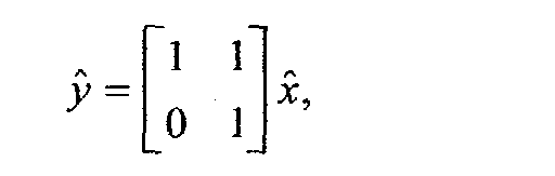
- Additionally,and

- Defining the observer output as 'residue' causes a roll rate fault to appear as a residue in the observer output while a roll angle 'measurement' error appears as only a transient noise. Moreover, suspension characteristic changes, modeled as disturbance d, do not affect the observer output. Resultantly the same observer design can be applied to various vehicle platforms without tuning.
- If the residue exceeds a pre-calibrated threshold, (which can be a pre-calibrated function of vehicle dynamic status,) a fault is suspected.
- If a fault condition is indicated during the aforementioned comparison for a short period of time, having a pre-calibrated length, during which time the system did not detect any fault from the source signal that generated reference roll angle, then a roll rate sensor fault is concluded. Alternately, to facilitate a faster detection, a condition is added to check if roll rate signal is away from zero (which is the normal value) during this period.
- Special fault detection: for sticky signal fault such that the roll rate signal sticks to a constant value, the following logic is developed:
- If (abs(high pass filtered rollrate) < threshold_1 holds true for more than a precalibrated constant. (abs(high pass filtered suspension roll angle (from lateral acceleration) )> threshold_2) holds true for more than a precalibrated constant (not necessarily continuously),
- then a fault is suspected. If this suspected situation has happened for more than a precalibrated number of times, set the fault flag.
-
- Following detection of a roll rate sensor fault, the
controller 26 responds by either shutting down thesafety system 18 or any of the sub-systems of thesafety system 18, such as roll-over control and compensation. Alternately, thecontroller 26 responds to roll rate sensor error by compensating for information that would normally be obtained from theroll rate sensor 31. In one embodiment, thecontroller 26 compensates for the roll rate sensor using signals from a combination sensors including, but not limited to: thelateral accelerometer 27, thelongitudinal accelerometer 28, thevertical accelerometer 29, theyaw rate sensor 30, thepitch rate sensor 32, thewheel speed sensors 20, the steering angle sensor 33 (hand-wheel sensor), and steering angle position sensors 34 (road-wheel sensors). Regardless of the controller response to roll rate fault, a further embodiment of the present invention includes a driver notification of roll rate sensor problems. - Referring now to Figure 4, a logic flow diagram 100 of a method for detecting a roll rate sensor fault is illustrated. Logic starts in
operation block 102, where a reference roll angle is generated from available signals other than the roll rate signal, as was discussed previously. - In
operation block 104, a roll rate sensor signal is generated from the roll rate sensor. - In
operation block 106, the reference roll angle is compared to the roll rate sensor signal. Inoperation block 108, a roll rate sensor fault signal is generated. - In operation, a method for detecting a roll rate sensor fault includes generating a reference roll angle in an inertial frame with available signals other than roll rate, generating a roll rate sensor signal, compensating the roll rate sensor signal for all valid signal biases, comparing the reference roll angle to the roll rate sensor signal through a kinematics relation and a dynamic interaction related by a vehicle suspension, and generating a roll rate sensor fault signal.
- While particular embodiments of the invention have been shown and described, numerous variations and alternate embodiments will occur to those skilled in the art. Accordingly, it is intended that the invention be limited only in terms of the appended claims.
Claims (16)
- A method for detecting a roll rate sensor fault comprising:generating a reference roll angle;generating a roll rate sensor signal;comparing said reference roll angle to said roll rate sensor signal; andgenerating a roll rate sensor fault signal in response to comparing said reference roll angle to said roll rate sensor signal.
- A method as recited in claim 1 further comprising compensating for a valid signal bias in said roll rate sensor signal.
- A method as recited in claim 2, wherein compensating for a valid signal bias further comprises adjusting an electrical long term bias over time with a minute adjustment at each sampling time or a sliding mode control.
- A method as recited in claim 2, wherein compensating for a valid signal bias further comprises adjusting a mechanical long term sensor alignment pitch angle with a minute adjustment at each sampling time during vehicle turning or a sliding mode control during vehicle turning.
- A method as recited in claim 2, wherein compensating for a valid signal bias further comprises halting roll rate sensor signal compensation in response to a fault flag or in response to a situation where compensation is unnecessary.
- A method as recited in claim 1, wherein generating said reference roll angle further comprises sensing at least one of lateral acceleration, yaw rate, vehicle longitudinal speed, vehicle roll angle, wheel speed, or a GPS.
- A method as recited in claim 1 further comprising refining said reference roll angle through steering wheel angle information to reduce a negligence error of a lateral velocity derivative.
- A method as recited in claim 1 further comprising refining said reference roll angle with a calculation of a dynamic relation between a vehicle lateral acceleration and a suspension roll motion.
- A method as recited in claim 1, wherein comparing said reference roll angle to said roll rate sensor signal comprises comparing a low pass filter version of a derivative of said reference roll angle with said roll rate sensor signal.
- A method as recited in claim 1, wherein comparing said reference roll angle to said roll rate sensor signal comprises comparing a high pass filtered reference roll angle with a high pass filtered version of an integration of said roll rate sensor signal.
- A method as recited in claim 1, wherein comparing said reference roll angle to said roll rate sensor signal comprises comparing said reference roll angle and said roll rate sensor signal through building a filter utilizing both a suspension dynamics and a kinematics relationship between roll angle and roll rate.
- A method as recited in claim 1, wherein comparing said reference roll angle to said roll rate sensor signal comprises comparing said reference roll angle to said roll rate sensor signal through an observer that utilizes a kinematics relation and a dynamics relation.
- A method as recited in claim 1, wherein comparing said reference roll angle to said roll rate sensor signal further comprises utilizing generating a dynamic bias estimate with a logic having said vehicle roll rate signal averaging to zero over a long period of time.
- A method as recited in claim 1, wherein generating said roll rate sensor fault signal further comprises generating a lateral acceleration signal;filtering said lateral acceleration signal;generating a filtered lateral acceleration signal;high pass filtering said roll rate sensor signal;generating a filtered roll rate sensor signal; andcomparing said filtered lateral acceleration signal to said filtered roll rate sensor signal.
- A method as recited in claim 1 further comprising shutting down a safety system in response to roll rate sensor fault or error.
- A method as recited in claim 1 further comprising generating a substitute signal for said roll rate signal in response to roll rate sensor fault.
Applications Claiming Priority (4)
| Application Number | Priority Date | Filing Date | Title |
|---|---|---|---|
| US40015502P | 2002-08-01 | 2002-08-01 | |
| US400155P | 2002-08-01 | ||
| US10/620,881 US6941205B2 (en) | 2002-08-01 | 2003-07-16 | System and method for deteching roll rate sensor fault |
| US620881P | 2003-07-16 |
Publications (2)
| Publication Number | Publication Date |
|---|---|
| EP1386802A1 true EP1386802A1 (en) | 2004-02-04 |
| EP1386802B1 EP1386802B1 (en) | 2011-03-30 |
Family
ID=32965343
Family Applications (1)
| Application Number | Title | Priority Date | Filing Date |
|---|---|---|---|
| EP03254788A Expired - Lifetime EP1386802B1 (en) | 2002-08-01 | 2003-07-31 | A method for detecting a roll rate sensor fault |
Country Status (3)
| Country | Link |
|---|---|
| US (2) | US6941205B2 (en) |
| EP (1) | EP1386802B1 (en) |
| DE (1) | DE60336527D1 (en) |
Cited By (10)
| Publication number | Priority date | Publication date | Assignee | Title |
|---|---|---|---|---|
| WO2005095133A1 (en) * | 2004-03-23 | 2005-10-13 | Kelsey-Hayes Company | Method and apparatus for vehicle rollover mitigation |
| EP1792759A3 (en) * | 2005-12-02 | 2007-11-21 | Mando Corporation | Vehicle suspension with height adjustment means |
| FR2916409A1 (en) * | 2007-05-25 | 2008-11-28 | Snr Roulements Sa | Rolling parameter e.g. mass, estimating method for e.g. commercial vehicle, involves utilizing Kalman filter for estimating parameter using observation model, where filter is integrated to dynamic parameter evaluation model |
| WO2009068346A1 (en) * | 2007-11-28 | 2009-06-04 | Robert Bosch Gmbh | Controller and method for activating personal protection means |
| EP2127988A1 (en) * | 2008-05-28 | 2009-12-02 | Delphi Technologies, Inc. | Kinematic-based method of estimating the absolute roll angle of a vehicle body |
| WO2011098333A1 (en) * | 2010-02-11 | 2011-08-18 | Continental Teves Ag & Co. Ohg | Vehicle sensor node |
| DE102013218043A1 (en) * | 2013-09-10 | 2015-03-12 | Continental Teves Ag & Co. Ohg | Method for providing relative measurement data for a fusion sensor |
| DE102005012458B4 (en) * | 2004-03-23 | 2015-05-21 | Continental Teves, Inc. | Method for protecting a motor vehicle against overturning |
| CN110912488A (en) * | 2019-11-20 | 2020-03-24 | 中国航空工业集团公司西安航空计算技术研究所 | Motor control method and system |
| CN121553083A (en) * | 2026-01-21 | 2026-02-24 | 浙江大学 | EMB clamping force control method based on hybrid optimization strategy |
Families Citing this family (46)
| Publication number | Priority date | Publication date | Assignee | Title |
|---|---|---|---|---|
| US7245995B2 (en) * | 2003-02-19 | 2007-07-17 | Robert Bosch Gmbh | Fault-tolerant vehicle stability control |
| JP2004322740A (en) * | 2003-04-22 | 2004-11-18 | Toyota Motor Corp | Failure diagnosis device for vehicle control device |
| DE10325548B4 (en) * | 2003-06-05 | 2005-07-14 | Munnix, Pascal, Dipl.-Ing. | Apparatus and method for measuring movement quantities of a motor vehicle |
| JP4145741B2 (en) * | 2003-07-03 | 2008-09-03 | 三菱電機株式会社 | Vehicle rollover discrimination device and vehicle rollover discrimination method |
| US6856868B1 (en) * | 2003-10-24 | 2005-02-15 | Ford Global Technologies, Llc | Kinetic energy density rollover detective sensing algorithm |
| US7206679B2 (en) * | 2004-01-08 | 2007-04-17 | Delphi Technologies, Inc. | Reconfigurable methodology for event detection in a motor vehicle |
| JP4251100B2 (en) * | 2004-03-25 | 2009-04-08 | 三菱ふそうトラック・バス株式会社 | Rollover suppression control device for vehicle |
| US7451032B2 (en) * | 2004-06-02 | 2008-11-11 | Ford Global Technologies, Llc | System and method for determining desired yaw rate and lateral velocity for use in a vehicle dynamic control system |
| US7162343B2 (en) * | 2004-09-17 | 2007-01-09 | Ford Global Technologies, Llc | Intelligent vehicle rollover detection methods and systems |
| DE102004055177B4 (en) * | 2004-11-16 | 2015-03-19 | Bayerische Motoren Werke Aktiengesellschaft | Operating procedure of a chassis control system |
| JP4483551B2 (en) * | 2004-11-30 | 2010-06-16 | 株式会社アドヴィックス | Vehicle motion control device |
| JP4639925B2 (en) * | 2005-04-21 | 2011-02-23 | 株式会社アドヴィックス | Rolling motion stabilization control device for vehicle |
| US20070005203A1 (en) * | 2005-06-30 | 2007-01-04 | Padma Sundaram | Vehicle diagnostic system and method for monitoring vehicle controllers |
| JP4155299B2 (en) * | 2005-12-26 | 2008-09-24 | トヨタ自動車株式会社 | Vehicle damping force control device |
| US20110093171A1 (en) * | 2006-02-21 | 2011-04-21 | Fabio Saposnik | Machine loss-of-control detector and shutdown system |
| US7970512B2 (en) * | 2006-08-30 | 2011-06-28 | Ford Global Technologies | Integrated control system for stability control of yaw, roll and lateral motion of a driving vehicle using an integrated sensing system with pitch information |
| US20100243791A1 (en) * | 2006-11-30 | 2010-09-30 | Honeywell International Inc. | Gyroscopic failure detection in a navigation device through sensor correlation |
| US7813851B2 (en) * | 2007-02-21 | 2010-10-12 | Autoliv Asp, Inc. | Sensing misalignment detection and estimation system |
| US7848864B2 (en) * | 2007-05-07 | 2010-12-07 | Gm Global Technology Operations, Inc. | System for estimating vehicle states for rollover reduction |
| US20090254244A1 (en) * | 2008-04-04 | 2009-10-08 | Li Xu | System and Method for Detecting a Pitch Rate Sensor Fault |
| DE102008021385B3 (en) * | 2008-04-29 | 2009-11-19 | Continental Automotive Gmbh | Method and apparatus for learning the rest position of the accelerator pedal of a motor vehicle |
| US20090299546A1 (en) * | 2008-05-28 | 2009-12-03 | Hac Aleksander B | Dynamic-based method of estimating the absolute roll angle of a vehicle body |
| US8095275B2 (en) * | 2008-08-28 | 2012-01-10 | Trw Automotive U.S. Llc | Method and apparatus for controlling an actuatable safety device |
| US10203033B2 (en) * | 2009-03-06 | 2019-02-12 | Eaton Cummins Automated Transmission Technologies Llc | Transmission control module with multiple sensor inputs |
| US9403415B2 (en) * | 2009-10-12 | 2016-08-02 | Ford Global Technologies | GPS based pitch sensing for an integrated stability control system |
| WO2011072662A1 (en) * | 2009-12-18 | 2011-06-23 | Conti Temic Microelectronic Gmbh | Monitoring computer in a control device |
| CN102686476B (en) * | 2009-12-25 | 2014-10-08 | 雅马哈发动机株式会社 | Driver characteristic judging device and saddled vehicle including said driver characteristic judging device |
| US9260096B2 (en) * | 2011-02-22 | 2016-02-16 | Nissin Kogyo Co., Ltd. | Brake fluid pressure control apparatus for vehicle |
| KR102055020B1 (en) * | 2011-03-02 | 2020-01-22 | 콘티넨탈 테베스 아게 운트 코. 오하게 | Intelligent vehicle sensor device |
| WO2014045859A1 (en) * | 2012-09-18 | 2014-03-27 | 株式会社村田製作所 | Hand cart |
| KR101500070B1 (en) * | 2013-04-15 | 2015-03-06 | 현대자동차주식회사 | System for estimating a road slope |
| WO2015058119A2 (en) * | 2013-10-17 | 2015-04-23 | Robert Bosch Gmbh | Validating automotive safety functions |
| DE102014200426B4 (en) * | 2014-01-13 | 2025-03-20 | Bayerische Motoren Werke Aktiengesellschaft | Method for robust detection of high-frequency signal interference |
| US9651948B2 (en) * | 2015-09-14 | 2017-05-16 | The Boeing Company | Roll attitude-dependent roll rate limit |
| US9873425B2 (en) | 2016-04-13 | 2018-01-23 | GM Global Technology Operations LLC | Detection and reconstruction of roll rate sensor fault |
| US10000215B2 (en) | 2016-04-13 | 2018-06-19 | GM Global Technology Operations LLC | Detection and reconstruction of pitch rate sensor fault |
| CN106301610A (en) * | 2016-08-29 | 2017-01-04 | 北京航空航天大学 | The adaptive failure detection of a kind of superhet and diagnostic method and device |
| US10502574B2 (en) | 2016-09-20 | 2019-12-10 | Waymo Llc | Devices and methods for a sensor platform of a vehicle |
| US10277084B1 (en) | 2016-10-19 | 2019-04-30 | Waymo Llc | Planar rotary transformer |
| US10988170B2 (en) * | 2018-12-11 | 2021-04-27 | Continental Automotive Systems, Inc. | Driver steer recommendation upon loss of one brake circuit of a diagonal spilt layout |
| US11964528B2 (en) | 2019-01-03 | 2024-04-23 | ClearMotion, Inc. | Slip control via active suspension for optimization of braking and accelerating of a vehicle |
| US11148678B2 (en) * | 2019-04-26 | 2021-10-19 | GM Global Technology Operations LLC | Controlling operation of a vehicle with a supervisory control module having a fault-tolerant controller |
| US11305602B2 (en) * | 2019-11-04 | 2022-04-19 | GM Global Technology Operations LLC | Vehicle detection and isolation system for detecting spring and stabilizing bar associated degradation and failures |
| CN118541295A (en) * | 2021-11-11 | 2024-08-23 | 康明斯有限公司 | Device, method and system for avoiding unintended vehicle acceleration |
| CN115042770B (en) * | 2022-06-16 | 2024-04-16 | 广东工业大学 | Vehicle queue transverse control method based on distributed robust model prediction |
| CN117760752B (en) * | 2023-12-13 | 2024-08-06 | 燕山大学 | An electro-hydraulic servo active suspension test platform and fault diagnosis method |
Citations (7)
| Publication number | Priority date | Publication date | Assignee | Title |
|---|---|---|---|---|
| US5842143A (en) * | 1994-03-25 | 1998-11-24 | Siemens Aktiengesellschaft | Circuit configuration for evaluating yaw rate sensor signals |
| US6038495A (en) * | 1998-02-06 | 2000-03-14 | Delco Electronics Corporation | Vehicle rollover sensing using short-term integration |
| EP1006026A2 (en) * | 1998-12-03 | 2000-06-07 | INDIANA MILLS & MANUFACTURING, INC. | Roll sensor system for a vehicle |
| US6227482B1 (en) * | 1998-03-27 | 2001-05-08 | Futaba Denshi Kogyo Kabushiki Kaisha | Gyroscope for remote-controlled helicopters |
| US6356188B1 (en) * | 2000-09-25 | 2002-03-12 | Ford Global Technologies, Inc. | Wheel lift identification for an automotive vehicle |
| US20020065591A1 (en) * | 2000-11-29 | 2002-05-30 | Schubert Peter James | Vehicle rollover detection apparatus and method |
| US20020095244A1 (en) * | 1999-12-21 | 2002-07-18 | Rhode Douglas Scott | Rollover stability control for an automotive vehicle using front wheel actuators |
Family Cites Families (210)
| Publication number | Priority date | Publication date | Assignee | Title |
|---|---|---|---|---|
| US2917126A (en) | 1957-04-04 | 1959-12-15 | Nolan Phillips | Driving control safety mechanism for tractors |
| US3604273A (en) | 1968-11-25 | 1971-09-14 | Aviat Electric Ltd | Angular rate sensor |
| US3608925A (en) | 1969-05-07 | 1971-09-28 | Peter H Murphy | Apparatus for offsetting centrifugal force affecting motor vehicles |
| US3899028A (en) | 1972-03-30 | 1975-08-12 | Systron Donner Corp | Angular position sensing and control system, apparatus and method |
| US4023864A (en) * | 1973-09-20 | 1977-05-17 | Lang Davis Industries, Inc. | Automatic stability control system with strain gauge sensors |
| US3972543A (en) | 1974-12-06 | 1976-08-03 | The Bendix Corporation | Combination vehicle yaw stabilizer |
| US3948567A (en) * | 1975-02-12 | 1976-04-06 | The Bendix Corporation | Sway control means for a trailer |
| USRE30550E (en) * | 1975-11-06 | 1981-03-24 | Durrell U. Howard | Automatic trailer sway sensing and brake applying system |
| FR2425342A1 (en) | 1978-05-12 | 1979-12-07 | Saint Marcel Ste Metallurg | Heavy vehicle anti-overturning retarder - has centrifugal acceleration detector emitting signal to solenoid operated brake valve and alarm circuit |
| SU816849A1 (en) | 1979-05-07 | 1981-03-30 | Ленинградский Ордена Трудовогокрасного Знамени Сельскохозяйственныйинститут | Device for preventing toppling of a vehicle |
| JPS6015015B2 (en) | 1979-06-29 | 1985-04-17 | 株式会社 レオ技研 | Road moisture detection device |
| JPS58152793A (en) | 1982-03-05 | 1983-09-10 | ティー・シー・エム株式会社 | Device for preventing turning-sideways of transport car |
| JPS60133526A (en) | 1983-12-21 | 1985-07-16 | Mitsubishi Metal Corp | Magnetic recording medium |
| JPS60163770A (en) * | 1984-02-02 | 1985-08-26 | Honda Motor Co Ltd | vehicle steering system |
| US4592565A (en) * | 1984-10-17 | 1986-06-03 | Leo Eagle | Apparatus for detecting an overturning moment in a moving vehicle, and jackknifing in a trailer-truck combination |
| JPH06104455B2 (en) * | 1985-03-15 | 1994-12-21 | 日産自動車株式会社 | Vehicle motion condition estimation device |
| US4650212A (en) * | 1985-03-20 | 1987-03-17 | Mazda Motor Corporation | Vehicle suspension system |
| EP0198450B1 (en) | 1985-04-13 | 1988-12-21 | Nissan Motor Co., Ltd. | Vehicle control system for controlling side slip angle and yaw rate gain |
| JP2532059B2 (en) * | 1985-09-13 | 1996-09-11 | 日産自動車株式会社 | Vehicle suspension control device |
| JPH0629039B2 (en) | 1986-01-10 | 1994-04-20 | 日産自動車株式会社 | Vehicle motion state estimation device |
| DE3606797C2 (en) * | 1986-03-01 | 2000-11-23 | Bosch Gmbh Robert | Device and method for controlling, in particular for limiting, the driving speed of a road vehicle |
| US4761022A (en) | 1986-03-08 | 1988-08-02 | Toyota Jidosha Kabushiki Kaisha | Suspension controller for improved turning |
| JPH0694253B2 (en) | 1986-03-17 | 1994-11-24 | トヨタ自動車株式会社 | Roll control device for vehicle |
| DE3616907A1 (en) | 1986-05-20 | 1987-11-26 | Hans Prof Dr Ing Marko | Device for controlling the speed of revolution of a motor vehicle about the vertical axis |
| JPS62291067A (en) | 1986-06-10 | 1987-12-17 | Nec Corp | Manufacture of thin film transistor |
| JPS63116918U (en) | 1987-01-19 | 1988-07-28 | ||
| JPS63203456A (en) | 1987-02-18 | 1988-08-23 | Mazda Motor Corp | Control device for driving force of automobile |
| JPH0419078Y2 (en) | 1987-03-26 | 1992-04-28 | ||
| JPH0829649B2 (en) | 1987-03-31 | 1996-03-27 | 日産自動車株式会社 | Active suspension device |
| DE3821610A1 (en) | 1988-06-27 | 1989-12-28 | Bayerische Motoren Werke Ag | CONTROL DEVICE FOR STABILIZING A VEHICLE |
| JPS6432918A (en) * | 1987-07-28 | 1989-02-02 | Mitsubishi Motors Corp | Active suspension controller |
| DE3826982C2 (en) * | 1987-08-10 | 2000-11-30 | Denso Corp | Auxiliary steering system connected to an anti-lock control system for use in motor vehicles |
| EP0312096B1 (en) | 1987-10-15 | 1992-12-30 | Mazda Motor Corporation | Friction detecting device for vehicles |
| JPH01122716A (en) | 1987-11-05 | 1989-05-16 | Hitachi Ltd | Automobile active suspension control system |
| DE3738221A1 (en) | 1987-11-11 | 1989-06-08 | Bayerische Motoren Werke Ag | METHOD AND DEVICE FOR DETECTING THE STATE OF A ROAD |
| JP2618250B2 (en) | 1987-12-22 | 1997-06-11 | 富士重工業株式会社 | Traction control device |
| DE3804587A1 (en) | 1988-02-13 | 1989-08-24 | Daimler Benz Ag | ADDITIONAL STEERING |
| DE3805589A1 (en) | 1988-02-23 | 1989-08-31 | Lucas Ind Plc | METHOD AND DEVICE FOR CONTROLLING A BRAKE SYSTEM FOR HEAVY VEHICLES |
| DE3815938C2 (en) | 1988-05-10 | 1996-09-19 | Bayerische Motoren Werke Ag | Acceleration sensor for vehicles |
| US4898431A (en) * | 1988-06-15 | 1990-02-06 | Aisin Seiki Kabushiki Kaisha | Brake controlling system |
| US5313389A (en) | 1988-09-13 | 1994-05-17 | Aisin Seiki Kabushiki Kaisha | Fail-safe mechanism for vehicle stability augmentation steering system |
| JP2768710B2 (en) * | 1988-09-17 | 1998-06-25 | ローベルト・ボッシュ・ゲゼルシャフト・ミット・ベシュレンクテル・ハフツング | A device that activates a protection device that protects a vehicle occupant |
| JP2565384B2 (en) * | 1988-09-30 | 1996-12-18 | 富士重工業株式会社 | Control device for automobile active suspension |
| GB8825540D0 (en) | 1988-11-01 | 1988-12-07 | Jaguar Cars | Air bag restraint systems |
| JPH0732331Y2 (en) * | 1989-01-18 | 1995-07-26 | 日産自動車株式会社 | Vehicle steering control device |
| US4998593A (en) * | 1989-03-31 | 1991-03-12 | Aisin Seiki Kabushiki Kaisha | Steering and brake controlling system |
| US5239868A (en) | 1989-05-19 | 1993-08-31 | Matsushita Electric Industrial Co., Ltd. | Angular rate detecting device |
| JP2000344085A (en) * | 1999-06-03 | 2000-12-12 | Toyota Motor Corp | Wheel control status display |
| JP2867448B2 (en) * | 1989-08-11 | 1999-03-08 | 株式会社日立製作所 | Active suspension control device |
| JPH0396468A (en) * | 1989-09-07 | 1991-04-22 | Honda Motor Co Ltd | Estimation method for fore and aft acceleration and deceleration of body |
| FR2655299B1 (en) | 1989-12-01 | 1992-02-21 | Renault | SAFETY SYSTEM FOR A MOTOR VEHICLE. |
| JPH0833408B2 (en) | 1990-03-29 | 1996-03-29 | 株式会社日立製作所 | Angle detection device, translational acceleration detection device, and vehicle control device |
| US5265020A (en) | 1990-04-20 | 1993-11-23 | Mazda Motor Corporation | Torque distribution control apparatus for four wheel drive |
| JP2762711B2 (en) * | 1990-07-02 | 1998-06-04 | 日産自動車株式会社 | Vehicle braking behavior compensator |
| JP2600986B2 (en) | 1990-07-06 | 1997-04-16 | 三菱自動車工業株式会社 | Rear wheel steering control method |
| JP2679415B2 (en) * | 1990-12-21 | 1997-11-19 | 日産自動車株式会社 | Vehicle braking force left / right distribution control device |
| DE4201146C2 (en) * | 1991-01-18 | 2003-01-30 | Hitachi Ltd | Device for controlling motor vehicle behavior |
| DE4121954A1 (en) * | 1991-07-03 | 1993-01-07 | Bosch Gmbh Robert | METHOD FOR OBTAINING THE YEAR SPEED AND / OR THE LATERAL SPEED |
| GB2257403A (en) | 1991-07-06 | 1993-01-13 | Gloster Saro Ltd | Road vehicle stability indicating system. |
| US5282134A (en) * | 1991-08-19 | 1994-01-25 | Automotive Systems Laboratory, Inc. | Slant transform/signal space crash discriminator |
| US5324102A (en) * | 1991-10-18 | 1994-06-28 | Fag Kugelfischer Georg Schafer Kgaa | Method and apparatus for regulating the braking force of motorcycles |
| US5335176A (en) | 1991-12-02 | 1994-08-02 | Koyo Seiko Co., Ltd. | Safety system for vehicles |
| JP3197330B2 (en) | 1992-04-10 | 2001-08-13 | 本田技研工業株式会社 | Vehicle driving force control device |
| US5548536A (en) | 1992-05-16 | 1996-08-20 | Daimler-Benz Ag | Method for determining quantities which characterize the driving behavior |
| JPH0616117A (en) | 1992-06-30 | 1994-01-25 | Honda Motor Co Ltd | Wheel longitudinal force control method in vehicle |
| DE4226746C1 (en) | 1992-08-13 | 1993-10-07 | Daimler Benz Ag | Method for determining a driving-dependent steering angle |
| DE4227886A1 (en) | 1992-08-22 | 1994-02-24 | Sel Alcatel Ag | Inclinometer for vehicle with body - contains inertial system or fibre optical gyroscope |
| DE4228893B4 (en) * | 1992-08-29 | 2004-04-08 | Robert Bosch Gmbh | System for influencing the driving dynamics of a motor vehicle |
| US5278761A (en) * | 1992-11-12 | 1994-01-11 | Ford Motor Company | Method for vehicular wheel spin control that adapts to different road traction characteristics |
| JP2882232B2 (en) | 1993-03-17 | 1999-04-12 | 三菱自動車工業株式会社 | Vehicle weight center slip angle measuring device |
| WO1994023272A1 (en) | 1993-03-30 | 1994-10-13 | Kazuhiro Okada | Multishaft angular velocity sensor |
| DE4335979A1 (en) | 1993-10-21 | 1995-04-27 | Telefunken Microelectron | Security management system (SMS) |
| DE4342732A1 (en) | 1993-12-15 | 1995-06-22 | Anton Ellinghaus Maschinenfabr | Tilt sensor for tanker vehicle |
| JP3303500B2 (en) * | 1994-02-02 | 2002-07-22 | トヨタ自動車株式会社 | Vehicle behavior control device |
| DE4405379A1 (en) * | 1994-02-19 | 1995-08-24 | Bosch Gmbh Robert | ABS braking system for vehicle |
| KR100207106B1 (en) | 1994-04-06 | 1999-07-15 | 정몽규 | Method and apparatus of taper for automobile testing road |
| KR950028978A (en) * | 1994-04-06 | 1995-11-22 | 전성원 | Shift pattern control device and method for steep slope and steep curve |
| US5446658A (en) | 1994-06-22 | 1995-08-29 | General Motors Corporation | Method and apparatus for estimating incline and bank angles of a road surface |
| JP3116738B2 (en) * | 1994-07-28 | 2000-12-11 | トヨタ自動車株式会社 | Vehicle behavior control device |
| US5610575A (en) * | 1994-08-25 | 1997-03-11 | Automotive Systems Laboratory, Inc. | Method and system for detecting vehicle roll-over |
| US5602734A (en) * | 1994-09-23 | 1997-02-11 | Advanced Safety Concepts, Inc. | Automobile air bag systems |
| JP3050061B2 (en) * | 1994-10-25 | 2000-06-05 | トヨタ自動車株式会社 | Occupant restraint |
| US5732379A (en) * | 1994-11-25 | 1998-03-24 | Itt Automotive Europe Gmbh | Brake system for a motor vehicle with yaw moment control |
| US5732377A (en) * | 1994-11-25 | 1998-03-24 | Itt Automotive Europe Gmbh | Process for controlling driving stability with a yaw rate sensor equipped with two lateral acceleration meters |
| DE19515050A1 (en) | 1994-11-25 | 1996-05-30 | Teves Gmbh Alfred | Motor vehicle ride stability regulation by brake pressure gradient control |
| US5732378A (en) * | 1994-11-25 | 1998-03-24 | Itt Automotive Europe Gmbh | Method for determining a wheel brake pressure |
| US5549328A (en) | 1995-01-17 | 1996-08-27 | Gabriel Ride Control Products, Inc. | Roll control system |
| JPH08258588A (en) | 1995-03-27 | 1996-10-08 | Mazda Motor Corp | Road surface condition detection device in vehicle |
| JP3042360B2 (en) | 1995-04-13 | 2000-05-15 | 日本ビクター株式会社 | Magnetic head reversing device |
| JP3463415B2 (en) | 1995-06-22 | 2003-11-05 | 日産自動車株式会社 | Vehicle yawing behavior control device |
| US5648903A (en) * | 1995-07-10 | 1997-07-15 | Ford Global Technologies, Inc. | Four wheel steering control utilizing front/rear tire longitudinal slip difference |
| DE19529539A1 (en) | 1995-08-11 | 1997-02-13 | Man Nutzfahrzeuge Ag | Procedure for the ON-BOARD determination of vehicle dynamic safety reserves of commercial vehicles |
| FI108084B (en) | 1995-09-08 | 2001-11-15 | Vaisala Oyj | Method and apparatus for measuring the properties of a road surface |
| JP3248411B2 (en) * | 1995-10-11 | 2002-01-21 | トヨタ自動車株式会社 | Vehicle behavior control device |
| JP3248413B2 (en) * | 1995-10-18 | 2002-01-21 | トヨタ自動車株式会社 | Vehicle behavior control device |
| JP3008833B2 (en) | 1995-10-25 | 2000-02-14 | トヨタ自動車株式会社 | Estimation device for vehicle body skidding speed |
| JP3627325B2 (en) * | 1995-11-17 | 2005-03-09 | アイシン精機株式会社 | Vehicle motion control device |
| JP3533420B2 (en) | 1995-12-05 | 2004-05-31 | トヨタ自動車株式会社 | Brake control device |
| DE19602879C1 (en) * | 1996-01-29 | 1997-08-07 | Knorr Bremse Systeme | Method for detecting the risk of a vehicle tipping over |
| AUPN786796A0 (en) * | 1996-02-05 | 1996-02-29 | Verward Pty Ltd (trading as Brooks Merchants) | Vehicle seat |
| DE19609176A1 (en) | 1996-03-11 | 1997-09-18 | Bosch Gmbh Robert | Method and arrangement for detecting a vehicle rollover |
| DE19609717A1 (en) * | 1996-03-13 | 1997-09-18 | Bosch Gmbh Robert | Arrangement for detecting rollover processes in vehicles |
| US5787375A (en) * | 1996-04-01 | 1998-07-28 | Ford Global Technologies, Inc. | Method for determining steering position of automotive steering mechanism |
| DE19615294A1 (en) | 1996-04-18 | 1997-10-23 | Bosch Gmbh Robert | Method and device for controlling the braking force on at least one wheel of a vehicle |
| US5742918A (en) * | 1996-04-26 | 1998-04-21 | Ford Global Technologies, Inc. | Method and apparatus for dynamically compensating a lateral acceleration of a motor vehicle |
| US5742919A (en) * | 1996-04-26 | 1998-04-21 | Ford Global Technologies, Inc. | Method and apparatus for dynamically determining a lateral velocity of a motor vehicle |
| US5809434A (en) | 1996-04-26 | 1998-09-15 | Ford Global Technologies, Inc. | Method and apparatus for dynamically determically determining an operating state of a motor vehicle |
| JPH09315277A (en) * | 1996-05-31 | 1997-12-09 | Unisia Jecs Corp | Vehicle motion control device |
| JP2877084B2 (en) | 1996-07-09 | 1999-03-31 | 三菱自動車工業株式会社 | Braking force control device |
| US5707117A (en) * | 1996-07-19 | 1998-01-13 | General Motors Corporation | Active brake control diagnostic |
| DE19655388B4 (en) * | 1996-08-16 | 2008-08-14 | Daimler Ag | Vehicle dynamics control system and method |
| DE19634728C1 (en) | 1996-08-28 | 1998-04-02 | Daimler Benz Ag | Vehicle steering |
| US5878357A (en) * | 1996-09-03 | 1999-03-02 | Ford Global Technologies, Inc. | Method and apparatus for vehicle yaw rate estimation |
| US5720533A (en) * | 1996-10-15 | 1998-02-24 | General Motors Corporation | Brake control system |
| JPH10119743A (en) * | 1996-10-23 | 1998-05-12 | Aisin Seiki Co Ltd | Vehicle motion control device |
| JPH10129439A (en) | 1996-10-25 | 1998-05-19 | Aisin Seiki Co Ltd | Vehicle motion control device |
| US5723782A (en) * | 1996-11-29 | 1998-03-03 | Bolles, Jr.; Robert C. | Method of land vehicle suspension evaluation and design through roll angle analysis |
| DE19650691C2 (en) * | 1996-12-07 | 1998-10-29 | Deutsch Zentr Luft & Raumfahrt | Method for steering assistance for a driver of a road vehicle |
| US5825284A (en) | 1996-12-10 | 1998-10-20 | Rollover Operations, Llc | System and method for the detection of vehicle rollover conditions |
| US5736939A (en) * | 1996-12-11 | 1998-04-07 | Caterpillar Inc. | Apparatus and method for determing a condition of a road |
| GB9626045D0 (en) * | 1996-12-14 | 1997-01-29 | Rover Group | A vehicle roll stabilising system |
| JP3493568B2 (en) * | 1997-02-12 | 2004-02-03 | 光洋精工株式会社 | Car steering system |
| FR2761039B1 (en) * | 1997-03-22 | 2002-05-31 | Bosch Gmbh Robert | METHOD AND DEVICE FOR IMPLEMENTING A GUIDANCE SYSTEM OF A MOTOR VEHICLE |
| US6186267B1 (en) * | 1997-03-22 | 2001-02-13 | Robert Bosch Gmbh | Method and apparatus for operating a steering system for a motor vehicle |
| US6226579B1 (en) * | 1997-03-22 | 2001-05-01 | Robert Bosch Gmbh | Method and apparatus for operating a steering system for a motor vehicle |
| JP3269421B2 (en) * | 1997-04-04 | 2002-03-25 | 三菱自動車工業株式会社 | Automatic vehicle deceleration control device |
| JP3045452U (en) | 1997-05-15 | 1998-02-03 | 株式会社ハイランドハウス | Cushioning material using wood shavings |
| JPH10329682A (en) | 1997-06-03 | 1998-12-15 | Mitsubishi Motors Corp | Vehicle rollover prevention device |
| JP3982011B2 (en) | 1997-06-24 | 2007-09-26 | 三菱ふそうトラック・バス株式会社 | Vehicle rollover prevention device |
| US6065558A (en) * | 1997-07-01 | 2000-05-23 | Dynamotive, L.L.C. | Anti-rollover brake system |
| JP3681259B2 (en) | 1997-07-23 | 2005-08-10 | 光洋精工株式会社 | Electric power steering device |
| US6026926A (en) * | 1997-07-25 | 2000-02-22 | Honda Giken Kogyo Kabushiki Kaisha | Electric power steering apparatus |
| JPH11194089A (en) * | 1997-08-20 | 1999-07-21 | Daimler Benz Ag | Determining method of road surface condition |
| DE19744085A1 (en) * | 1997-10-06 | 1999-04-08 | Bosch Gmbh Robert | System producing trigger signal for vehicle safety unit with collision with low obstacle |
| US6035251A (en) | 1997-11-10 | 2000-03-07 | General Motors Corporation | Brake system control method employing yaw rate and ship angle control |
| DE19751935A1 (en) * | 1997-11-22 | 1999-05-27 | Bosch Gmbh Robert | Method and device for determining a quantity describing the center of gravity of a vehicle |
| DE19751839A1 (en) | 1997-11-22 | 1999-05-27 | Bosch Gmbh Robert | Tilt tendency detection in vehicle |
| DE19751867A1 (en) | 1997-11-22 | 1999-05-27 | Bosch Gmbh Robert | Tilt tendency detection in vehicle |
| DE19751925A1 (en) | 1997-11-22 | 1999-05-27 | Bosch Gmbh Robert | Tilt tendency detection method for vehicles for stabilization and roll-over prevention of heavy duty vehicle |
| JPH11170992A (en) | 1997-12-10 | 1999-06-29 | Mitsubishi Motors Corp | Vehicle rollover prevention device |
| EP1040033B1 (en) * | 1997-12-16 | 2005-04-06 | Continental Teves AG & Co. oHG | Method for improving tilt stability in a motor vehicle |
| DE19802041A1 (en) * | 1998-01-21 | 1999-07-22 | Bosch Gmbh Robert | Procedure for stabilizing car to avoid tipping over, especially for about axis oriented in car's longitudinal direction |
| GB9801780D0 (en) * | 1998-01-29 | 1998-03-25 | Rover Group | A roll damper arrangement |
| US5971503A (en) | 1998-02-03 | 1999-10-26 | Ford Global Technologies, Inc. | Hydraulic control unit with ambient temperature compensation during fluid pressure delivery |
| US6002974A (en) * | 1998-02-06 | 1999-12-14 | Delco Electronics Corporation | Vehicle rollover sensing using extended kalman filter |
| US6002975A (en) | 1998-02-06 | 1999-12-14 | Delco Electronics Corporation | Vehicle rollover sensing |
| JPH11254992A (en) | 1998-03-09 | 1999-09-21 | Mitsubishi Motors Corp | Vehicle rollover tendency determination device and rollover prevention device using the device |
| JP3436119B2 (en) | 1998-03-11 | 2003-08-11 | トヨタ自動車株式会社 | Body roll suppression control device |
| DE19812237C1 (en) * | 1998-03-20 | 1999-09-23 | Daimler Chrysler Ag | Method for driving dynamics control on a road vehicle |
| US5946644A (en) | 1998-03-30 | 1999-08-31 | Chrysler Corporation | Steering center indicator device |
| GB9806969D0 (en) | 1998-04-01 | 1998-06-03 | Lucas Ind Plc | Improvements relating to vehicle steering systems |
| KR100572500B1 (en) | 1998-04-07 | 2006-04-24 | 로베르트 보쉬 게엠베하 | Vehicle stabilization method and device |
| JP3345346B2 (en) | 1998-04-24 | 2002-11-18 | 日野自動車株式会社 | Estimation arithmetic unit for height of center of gravity of vehicle |
| JP3369467B2 (en) | 1998-04-24 | 2003-01-20 | 日野自動車株式会社 | Estimation arithmetic unit for height of center of gravity of vehicle |
| US6089344A (en) | 1998-06-01 | 2000-07-18 | Ford Global Technologies, Inc. | Method and apparatus for determining the center position of a steering system |
| GB9812274D0 (en) * | 1998-06-09 | 1998-08-05 | Rover Group | Hydraulic control systems |
| GB9812264D0 (en) | 1998-06-09 | 1998-08-05 | Rover Group | Vehicle roll control |
| JP3252797B2 (en) | 1998-06-19 | 2002-02-04 | トヨタ自動車株式会社 | Rollover determination method |
| US6050360A (en) * | 1998-06-24 | 2000-04-18 | General Motors Corporation | Apparatus and method for producing a desired return torque in a vehicle power steering system having a rotational steering position sensor |
| US6438464B1 (en) | 1998-07-16 | 2002-08-20 | Continental Teves Ag & Co., Ohg | Method and device for detecting the overturning hazard of a motor vehicle |
| US6198988B1 (en) * | 1998-08-10 | 2001-03-06 | Ford Global Technologies, Inc. | Method for detecting an erroneous direction of travel signal |
| US6073065A (en) * | 1998-09-04 | 2000-06-06 | Ford Global Technologies, Inc. | Method for detecting a bank angle experienced by a moving vehicle |
| US6169939B1 (en) * | 1998-09-08 | 2001-01-02 | Ford Global Technologies, Inc. | Method of generating a vehicle lateral acceleration signal for use in an active tilt control system |
| JP3816679B2 (en) | 1998-09-17 | 2006-08-30 | 株式会社東海理化電機製作所 | Rotation angle detector |
| GB9821064D0 (en) | 1998-09-29 | 1998-11-18 | Rover Group | Vehicle roll control |
| GB2342078B (en) | 1998-09-29 | 2002-05-08 | Rover Group | Vehicle roll control |
| DE19844540A1 (en) | 1998-09-29 | 2000-03-30 | Bosch Gmbh Robert | Arrangements and methods for avoiding rollovers when braking or accelerating for motor vehicles |
| JP3497746B2 (en) * | 1998-10-26 | 2004-02-16 | 本田技研工業株式会社 | Electric power steering device |
| US6314329B1 (en) | 1998-11-06 | 2001-11-06 | Visteon Global Technologies, Inc. | Compensation algorithm for initializing yaw rate sensor's zero point offset |
| US6179394B1 (en) * | 1998-11-09 | 2001-01-30 | General Motors Corporation | Active brake balance control method |
| US6062336A (en) * | 1998-11-13 | 2000-05-16 | General Motors Corporation | Adaptive variable effort power steering system |
| US6161905A (en) | 1998-11-19 | 2000-12-19 | General Motors Corporation | Active brake control including estimation of yaw rate and slip angle |
| US6292759B1 (en) | 1998-11-19 | 2001-09-18 | Delphi Technologies, Inc. | Vehicle attitude angle estimation using sensed signal blending |
| US6678631B2 (en) | 1998-11-19 | 2004-01-13 | Delphi Technologies, Inc. | Vehicle attitude angle estimator and method |
| US6195606B1 (en) * | 1998-12-07 | 2001-02-27 | General Motors Corporation | Vehicle active brake control with bank angle compensation |
| US6144904A (en) | 1998-12-22 | 2000-11-07 | Ford Global Technologies, Inc. | Instant detection / diagnosis of abrupt bias fault in signals of vehicle motion sensors |
| US6202009B1 (en) * | 1998-12-22 | 2001-03-13 | Ford Global Technologies, Inc. | Method for detecting fault of vehicle motion sensors |
| US6122568A (en) | 1998-12-22 | 2000-09-19 | Ford Global Technologies, Inc. | Method and apparatus for determining the dynamic stability of an automotive vehicle |
| US6185485B1 (en) * | 1998-12-22 | 2001-02-06 | Ford Global Technologies, Inc | Relative vehicle platform having synchronized adaptive offset calibration for lateral accelerometer and steering angle sensor |
| JP2000198453A (en) * | 1998-12-29 | 2000-07-18 | Robert Bosch Gmbh | Vehicle steer-by-wire steering system |
| JP3726557B2 (en) | 1999-05-26 | 2005-12-14 | トヨタ自動車株式会社 | Roll suppression control device for vehicle |
| US6278930B1 (en) | 1999-06-01 | 2001-08-21 | Toyota Jidosha Kabushiki Kaisha | Device for controlling spin/driftout of vehicle compatibly with roll control |
| JP3506048B2 (en) | 1999-06-08 | 2004-03-15 | トヨタ自動車株式会社 | Vehicle behavior control device |
| US6141605A (en) | 1999-06-25 | 2000-10-31 | Ford Global Technologies, Inc. | Determining the direction of travel of an automotive vehicle from yaw rate and relative steering wheel angle |
| US6202020B1 (en) * | 1999-08-20 | 2001-03-13 | Meritor Heavy Vehicle Systems, Llc | Method and system for determining condition of road |
| JP3463622B2 (en) | 1999-09-14 | 2003-11-05 | トヨタ自動車株式会社 | Vehicle behavior control device |
| US6233510B1 (en) * | 1999-10-15 | 2001-05-15 | Meritor Heavy Vehicle Technology, Llc | Method and system for predicting road profile |
| US6332104B1 (en) | 1999-12-21 | 2001-12-18 | Ford Global Technologies, Inc. | Roll over detection for an automotive vehicle |
| US6324446B1 (en) | 1999-12-21 | 2001-11-27 | Ford Global Technologies, Inc. | Roll over stability control for an automotive vehicle |
| US6456905B2 (en) | 1999-12-22 | 2002-09-24 | Honeywell International, Inc. | Method and apparatus for limiting attitude drift during turns |
| DE10000550B4 (en) | 2000-01-08 | 2005-09-15 | Bayerische Motoren Werke Ag | Device for detecting flashovers in a vehicle |
| US6282474B1 (en) | 2000-06-04 | 2001-08-28 | Ford Global Technologies, Inc. | Method and apparatus for detecting rollover of an automotive vehicle |
| US6266596B1 (en) | 2000-06-13 | 2001-07-24 | Caterpillar Inc. | Method and apparatus for controlling a mobile machine during start-up |
| JP4396002B2 (en) * | 2000-06-27 | 2010-01-13 | トヨタ自動車株式会社 | Vehicle traction control device |
| JP3960740B2 (en) * | 2000-07-31 | 2007-08-15 | トヨタ自動車株式会社 | Brake control device for vehicle |
| US6397127B1 (en) * | 2000-09-25 | 2002-05-28 | Ford Global Technologies, Inc. | Steering actuated wheel lift identification for an automotive vehicle |
| JP2002107371A (en) * | 2000-09-29 | 2002-04-10 | Toyota Motor Corp | Wheel rotation state detector |
| JP2002104149A (en) * | 2000-09-29 | 2002-04-10 | Toyota Motor Corp | Wheel rotation state detector |
| US6498976B1 (en) | 2000-10-30 | 2002-12-24 | Freightliner Llc | Vehicle operator advisor system and method |
| US6477480B1 (en) | 2000-11-15 | 2002-11-05 | Ford Global Technologies, Inc. | Method and apparatus for determining lateral velocity of a vehicle |
| JP3736340B2 (en) * | 2000-12-14 | 2006-01-18 | トヨタ自動車株式会社 | Vehicle control device |
| JP3518509B2 (en) | 2000-12-28 | 2004-04-12 | トヨタ自動車株式会社 | Rollover judgment device |
| US6351694B1 (en) * | 2001-01-16 | 2002-02-26 | Ford Global Technologies, Inc. | Method for robust estimation of road bank angle |
| US6644454B2 (en) | 2001-01-23 | 2003-11-11 | Toyota Jidosha Kabushiki Kaisha | Running condition control system for vehicle and method |
| US6799092B2 (en) | 2001-02-21 | 2004-09-28 | Ford Global Technologies, Llc | Rollover stability control for an automotive vehicle using rear wheel steering and brake control |
| US6529811B2 (en) * | 2001-03-01 | 2003-03-04 | Automotive Systems Laboratory, Inc. | Vehicle rollover detection system |
| US6600985B2 (en) | 2001-03-26 | 2003-07-29 | Indiana Mills & Manufacturing, Inc. | Roll sensor system for a vehicle |
| DE10115217C1 (en) | 2001-03-28 | 2002-08-14 | Bosch Gmbh Robert | Method for determining the angular position of a vehicle |
| US7107136B2 (en) * | 2001-08-29 | 2006-09-12 | Delphi Technologies, Inc. | Vehicle rollover detection and mitigation using rollover index |
| US6556908B1 (en) * | 2002-03-04 | 2003-04-29 | Ford Global Technologies, Inc. | Attitude sensing system for an automotive vehicle relative to the road |
-
2003
- 2003-07-16 US US10/620,881 patent/US6941205B2/en not_active Expired - Fee Related
- 2003-07-31 EP EP03254788A patent/EP1386802B1/en not_active Expired - Lifetime
- 2003-07-31 DE DE60336527T patent/DE60336527D1/en not_active Expired - Lifetime
- 2003-12-22 US US10/745,349 patent/US7110870B2/en not_active Expired - Fee Related
Patent Citations (7)
| Publication number | Priority date | Publication date | Assignee | Title |
|---|---|---|---|---|
| US5842143A (en) * | 1994-03-25 | 1998-11-24 | Siemens Aktiengesellschaft | Circuit configuration for evaluating yaw rate sensor signals |
| US6038495A (en) * | 1998-02-06 | 2000-03-14 | Delco Electronics Corporation | Vehicle rollover sensing using short-term integration |
| US6227482B1 (en) * | 1998-03-27 | 2001-05-08 | Futaba Denshi Kogyo Kabushiki Kaisha | Gyroscope for remote-controlled helicopters |
| EP1006026A2 (en) * | 1998-12-03 | 2000-06-07 | INDIANA MILLS & MANUFACTURING, INC. | Roll sensor system for a vehicle |
| US20020095244A1 (en) * | 1999-12-21 | 2002-07-18 | Rhode Douglas Scott | Rollover stability control for an automotive vehicle using front wheel actuators |
| US6356188B1 (en) * | 2000-09-25 | 2002-03-12 | Ford Global Technologies, Inc. | Wheel lift identification for an automotive vehicle |
| US20020065591A1 (en) * | 2000-11-29 | 2002-05-30 | Schubert Peter James | Vehicle rollover detection apparatus and method |
Cited By (17)
| Publication number | Priority date | Publication date | Assignee | Title |
|---|---|---|---|---|
| WO2005095133A1 (en) * | 2004-03-23 | 2005-10-13 | Kelsey-Hayes Company | Method and apparatus for vehicle rollover mitigation |
| US7894955B2 (en) | 2004-03-23 | 2011-02-22 | Kelsey-Hayes Company | Method and apparatus for vehicle rollover mitigation |
| DE102005012458B4 (en) * | 2004-03-23 | 2015-05-21 | Continental Teves, Inc. | Method for protecting a motor vehicle against overturning |
| EP1792759A3 (en) * | 2005-12-02 | 2007-11-21 | Mando Corporation | Vehicle suspension with height adjustment means |
| FR2916409A1 (en) * | 2007-05-25 | 2008-11-28 | Snr Roulements Sa | Rolling parameter e.g. mass, estimating method for e.g. commercial vehicle, involves utilizing Kalman filter for estimating parameter using observation model, where filter is integrated to dynamic parameter evaluation model |
| US8648704B2 (en) | 2007-11-28 | 2014-02-11 | Robert Bosch Gmbh | Control device and method for triggering passenger protection devices |
| WO2009068346A1 (en) * | 2007-11-28 | 2009-06-04 | Robert Bosch Gmbh | Controller and method for activating personal protection means |
| EP2127988A1 (en) * | 2008-05-28 | 2009-12-02 | Delphi Technologies, Inc. | Kinematic-based method of estimating the absolute roll angle of a vehicle body |
| CN102753395A (en) * | 2010-02-11 | 2012-10-24 | 大陆-特韦斯贸易合伙股份公司及两合公司 | Vehicle sensor node |
| US8855867B2 (en) | 2010-02-11 | 2014-10-07 | Continental Teves Ag & Co., Ohg | Vehicle sensor node |
| WO2011098333A1 (en) * | 2010-02-11 | 2011-08-18 | Continental Teves Ag & Co. Ohg | Vehicle sensor node |
| CN102753395B (en) * | 2010-02-11 | 2015-12-02 | 大陆-特韦斯贸易合伙股份公司及两合公司 | Vehicle sensor node |
| DE102013218043A1 (en) * | 2013-09-10 | 2015-03-12 | Continental Teves Ag & Co. Ohg | Method for providing relative measurement data for a fusion sensor |
| DE102013218043B4 (en) | 2013-09-10 | 2024-06-20 | Continental Automotive Technologies GmbH | Method for providing relative measurement data for a fusion sensor |
| CN110912488A (en) * | 2019-11-20 | 2020-03-24 | 中国航空工业集团公司西安航空计算技术研究所 | Motor control method and system |
| CN110912488B (en) * | 2019-11-20 | 2023-09-05 | 中国航空工业集团公司西安航空计算技术研究所 | Motor control method and system |
| CN121553083A (en) * | 2026-01-21 | 2026-02-24 | 浙江大学 | EMB clamping force control method based on hybrid optimization strategy |
Also Published As
| Publication number | Publication date |
|---|---|
| US20040059480A1 (en) | 2004-03-25 |
| US20040181329A1 (en) | 2004-09-16 |
| DE60336527D1 (en) | 2011-05-12 |
| EP1386802B1 (en) | 2011-03-30 |
| US7110870B2 (en) | 2006-09-19 |
| US6941205B2 (en) | 2005-09-06 |
Similar Documents
| Publication | Publication Date | Title |
|---|---|---|
| US6941205B2 (en) | System and method for deteching roll rate sensor fault | |
| Hac et al. | Detection of vehicle rollover | |
| US6782315B2 (en) | Method and apparatus for compensating misalignments of a sensor system used in a vehicle dynamic control system | |
| US7092808B2 (en) | Integrated sensing system for an automotive system | |
| US7010409B2 (en) | Reference signal generator for an integrated sensing system | |
| US7079928B2 (en) | System and method for determining a wheel departure angle for a rollover control system with respect to road roll rate and loading misalignment | |
| EP1362748B1 (en) | Roll sensor system for a vehicle | |
| US7797091B2 (en) | Rollover judgment apparatus | |
| US7031816B2 (en) | Active rollover protection | |
| US20090299546A1 (en) | Dynamic-based method of estimating the absolute roll angle of a vehicle body | |
| US7194351B2 (en) | System and method for determining a wheel departure angle for a rollover control system | |
| EP2127988A1 (en) | Kinematic-based method of estimating the absolute roll angle of a vehicle body | |
| EP1124701A1 (en) | Vehicle suspensions | |
| EP1386808B1 (en) | System and method for characterizing vehicle body to road angle for vehicle roll stability control | |
| US20070129865A1 (en) | Vehicle height controlling suspension apparatus having signal-freeze determining function and vehicle height control method thereof | |
| CN101218136A (en) | Determination of current yaw angle and current sideslip angle of land vehicle | |
| US10793132B2 (en) | Vehicle motion detecting apparatus | |
| US20090254244A1 (en) | System and Method for Detecting a Pitch Rate Sensor Fault | |
| US20100131141A1 (en) | Bank angle estimation via vehicle lateral velocity with force tables | |
| US8185271B2 (en) | Methods and device for determining the roll angle for occupant protection devices | |
| EP1760451A1 (en) | Method and system for road surface friction coefficient estimation | |
| US20060190143A1 (en) | System to measure wheel liftoff | |
| KR101078248B1 (en) | Rough road detection method for electronic stability program | |
| KR20090011725A (en) | Yorate Sensor Offset Correction and Failure Detection Method | |
| JP2000019002A (en) | Vehicle mass estimation device |
Legal Events
| Date | Code | Title | Description |
|---|---|---|---|
| PUAI | Public reference made under article 153(3) epc to a published international application that has entered the european phase |
Free format text: ORIGINAL CODE: 0009012 |
|
| AK | Designated contracting states |
Kind code of ref document: A1 Designated state(s): AT BE BG CH CY CZ DE DK EE ES FI FR GB GR HU IE IT LI LU MC NL PT RO SE SI SK TR |
|
| AX | Request for extension of the european patent |
Extension state: AL LT LV MK |
|
| 17P | Request for examination filed |
Effective date: 20040712 |
|
| AKX | Designation fees paid |
Designated state(s): DE GB |
|
| RAP1 | Party data changed (applicant data changed or rights of an application transferred) |
Owner name: FORD GLOBAL TECHNOLOGIES, LLC. |
|
| 17Q | First examination report despatched |
Effective date: 20061010 |
|
| GRAP | Despatch of communication of intention to grant a patent |
Free format text: ORIGINAL CODE: EPIDOSNIGR1 |
|
| GRAS | Grant fee paid |
Free format text: ORIGINAL CODE: EPIDOSNIGR3 |
|
| GRAA | (expected) grant |
Free format text: ORIGINAL CODE: 0009210 |
|
| AK | Designated contracting states |
Kind code of ref document: B1 Designated state(s): DE GB |
|
| REG | Reference to a national code |
Ref country code: GB Ref legal event code: FG4D |
|
| REF | Corresponds to: |
Ref document number: 60336527 Country of ref document: DE Date of ref document: 20110512 Kind code of ref document: P |
|
| REG | Reference to a national code |
Ref country code: DE Ref legal event code: R096 Ref document number: 60336527 Country of ref document: DE Effective date: 20110512 |
|
| PGFP | Annual fee paid to national office [announced via postgrant information from national office to epo] |
Ref country code: GB Payment date: 20110722 Year of fee payment: 9 |
|
| PLBE | No opposition filed within time limit |
Free format text: ORIGINAL CODE: 0009261 |
|
| STAA | Information on the status of an ep patent application or granted ep patent |
Free format text: STATUS: NO OPPOSITION FILED WITHIN TIME LIMIT |
|
| 26N | No opposition filed |
Effective date: 20120102 |
|
| REG | Reference to a national code |
Ref country code: DE Ref legal event code: R097 Ref document number: 60336527 Country of ref document: DE Effective date: 20120102 |
|
| GBPC | Gb: european patent ceased through non-payment of renewal fee |
Effective date: 20120731 |
|
| PG25 | Lapsed in a contracting state [announced via postgrant information from national office to epo] |
Ref country code: GB Free format text: LAPSE BECAUSE OF NON-PAYMENT OF DUE FEES Effective date: 20120731 |
|
| PGFP | Annual fee paid to national office [announced via postgrant information from national office to epo] |
Ref country code: DE Payment date: 20160801 Year of fee payment: 14 |
|
| REG | Reference to a national code |
Ref country code: DE Ref legal event code: R119 Ref document number: 60336527 Country of ref document: DE |
|
| PG25 | Lapsed in a contracting state [announced via postgrant information from national office to epo] |
Ref country code: DE Free format text: LAPSE BECAUSE OF NON-PAYMENT OF DUE FEES Effective date: 20180201 |