EP1386827A2 - Hilfsrahmen für Kraftfahrzeuge - Google Patents
Hilfsrahmen für Kraftfahrzeuge Download PDFInfo
- Publication number
- EP1386827A2 EP1386827A2 EP03010964A EP03010964A EP1386827A2 EP 1386827 A2 EP1386827 A2 EP 1386827A2 EP 03010964 A EP03010964 A EP 03010964A EP 03010964 A EP03010964 A EP 03010964A EP 1386827 A2 EP1386827 A2 EP 1386827A2
- Authority
- EP
- European Patent Office
- Prior art keywords
- housing
- subframe according
- cross member
- motor vehicle
- subframe
- Prior art date
- Legal status (The legal status is an assumption and is not a legal conclusion. Google has not performed a legal analysis and makes no representation as to the accuracy of the status listed.)
- Granted
Links
Images


Classifications
-
- B—PERFORMING OPERATIONS; TRANSPORTING
- B62—LAND VEHICLES FOR TRAVELLING OTHERWISE THAN ON RAILS
- B62D—MOTOR VEHICLES; TRAILERS
- B62D21/00—Understructures, i.e. chassis frame on which a vehicle body may be mounted
- B62D21/11—Understructures, i.e. chassis frame on which a vehicle body may be mounted with resilient means for suspension, e.g. of wheels or engine; sub-frames for mounting engine or suspensions
Definitions
- the invention relates to a subframe for motor vehicles, according to the preamble of claim 1.
- Such as subframe designated auxiliary frame offer in addition to a excellent decoupling of interference on the body and the body the motor vehicle and the advantage that z. B. in a front-wheel drive Motor vehicle suspension, the entire drive unit with engine and speed change gear and the rack and pinion steering as an assembly unit can be installed in the motor vehicle.
- Such a However subframe can also be used as a rear unit in a motor vehicle All-wheel steering can be used.
- the object of the invention is to propose a subframe of the generic type, the simpler and manufacturing technology is cheaper and the further mounting advantages allows.
- one of the cross member directly is formed by the housing of the rack-and-pinion steering gear and that Housing with the side rails is detachably connected.
- the invention is a cross member of the subframe directly through the Housing of the rack-and-pinion steering gear replaced. Due to the detachable attachment (usually by means of screws) can also be the steering gear at incurred repairs are easily upgraded.
- the housing can be unscrewed downwards be attached to the side rails. This is a possibly required expansion of Further simplified steering gear, wherein the longitudinal members and all located on these Attachments remain unaffected or do not need to be dismantled.
- the housing is set back up Areas of the side members is inserted and that the fastening sections of the housing are designed so that the associated material weakenings the side members are balanced.
- bridge members can be attached to this attachment to the attachment sections with in particular in the longitudinal direction deformation-resistant walls be formed.
- the housing of the steering gear by truss-like stiffeners with a top flange and / or be strengthened a lower chord. This can both while driving the motor vehicle occurring bending moments and the required higher bending stiffness of the steering gear can be ensured.
- the power pack can be the engine (internal combustion engine) or the speed change gear or a rear differential be of the motor vehicle.
- the other cross member when removing the drive unit, can also be removed and dismantled downwards be formed and can all body - side bearing mounts to the Be arranged longitudinal beams.
- the drive unit Lowerable or expandable or it can be easier Make the steering gear or the other crossbar dismantled down (for example, if a lower sump of an aggregate or other Aggregate parts would be dismantled).
- the housing can be manufactured in a favorable manner and / or the further cross member made of a light metal alloy and preferably in Die casting process to be made. Due to the excellent possible Adaptation of the components to the specific loads to achieve uniform component stresses (ribbing, wall thickness, etc.) can be lightweight, structurally and cost-effective components at low cycle times to be provided.
- an auxiliary frame 10 is shown in simplified form, consisting of two Side members 12, 14 and two cross members 16, 18 composed.
- the subframe 10 is uniformly designated by 20 shots on the side rails 12, 14 and sound insulation not shown on rubber mounts on Attached structure of the motor vehicle.
- side members 12, 14 in a conventional manner uniform with 22 designated recordings for suspension elements, not shown for the suspension of the motor vehicle.
- 24 receptacles 24 are arranged on the cross members 16, by means of derer not shown drive unit of the motor vehicle in one Three-point bearing (one four-point bearing with two rear shots 24 would alternatively be possible) is suspended via appropriate rubber bearings.
- the Drive unit is the engine in the case of a front-wheel drive motor vehicle (Internal combustion engine) and the speed change gearbox with integrated Front axle.
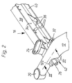
- the front cross member 16 is through the housing (also designated 16) formed of the rack-and-pinion steering gear of the motor vehicle, whose Querverschiertze rack 26 (see also Fig. 2 and 3) with the steerable Wheels of the motor vehicle leading tie rods 28, 30 hingedly connected is.
- the not apparent drive pinion of the steering gear is on the Steering shaft 32 of the steering gear in a known manner with the steering column and the steering wheel of the motor vehicle (not shown) drivingly connected.
- the rack and pinion steering gear is more conventional Design type.
- the housing 16 made of a light metal alloy has a tubular portion 34, on the framework-like stiffening walls 36, a top flange 38th and a lower flange 40 of defined wall thickness are cast.
- the tubular, the rack 26 receiving housing 34, the upper flange 38 and the Bottom chord 40 run laterally to attachment portions 42 together, as they in the longitudinal section of FIG. 3 can be seen.
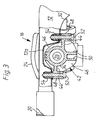
- the attachment portion 42 shown in connection with the longitudinal member 12 (the opposite side on the longitudinal member 14 is mirror-inverted) of the housing 16 is in an upwardly recessed area 12a of the longitudinal member 12 inserted from below and by means of a tubular Housing 34 molded bridge member 44 with two screw pipes 48th fastened by means of screws 52.
- the penetrating the screw pipes 48 Screws 52 are screwed into threaded nuts 54 of the longitudinal member 12.
- the cross member with a horizontal Forming direction attachment portion, so that the connecting means can be arranged in a horizontal direction.
- the bridge member 44 is provided with two encircling the tubular housing 34, radially aligned walls 46 provided (in the sectional view is only a circumferential wall 46 visible), on the one hand to the tubular housing 34 and to the intermediate screw pipes 48 on the other are connected.
- the two circumferential walls 46 are with transverse walls 50 additionally cross-braced.
- the attachment portions 42 and the bridge members 44 with the walls 46, 50 are designed so stiff that through the recessed area 12a of the longitudinal member 12 and 14 resulting weakening in the buckling stiffness is eliminated.
- Fig. 4 finally shows sections of the rear cross member 18, the made of a light metal alloy is cast and with bilateral Flange sections 60 by means of two screws 62 from below to the Side members 12, 14 is attached.
- the cross member 18 consists essentially of a top flange 64, two side walls 66 and the side walls 66 truss-like connecting stiffening ribs 68 together.
- the housing 16 and formed by this cross member 16 and the cross member 18 are made by die casting from an aluminum alloy.
- the manufacture is not limited to the die casting method. Also possible are other common production methods for light metal, such as z. B. chill casting or sand casting.
Landscapes
- Engineering & Computer Science (AREA)
- Chemical & Material Sciences (AREA)
- Combustion & Propulsion (AREA)
- Transportation (AREA)
- Mechanical Engineering (AREA)
- Body Structure For Vehicles (AREA)
Abstract
Description
- Fig. 1
- in vereinfachter Darstellung eine Draufsicht auf einen Hilfsrahmen für ein frontgetriebenes Kraftfahrzeug mit zwei Längsträgern, zwei Querträgern und Aufnahmen zur Befestigung am Aufbau, für Radaufhängungen und für Lager des Antriebsaggregates;
- Fig. 2
- in raumbildlicher Darstellung abschnittsweise den linken Längsträger und das Gehäuse des Zahnstangen-Lenkgetriebes des Hilfsrahmens nach Fig. 1;
- Fig. 3
- einen Schnitt gemäß Linie III - III der Fig. 2 durch den Längsträger mit dem Befestigungsabschnitt des Lenkgetriebes; und
- Fig. 4
- abschnittsweise den linken Längsträger des Hilfsrahmens nach Fig. 1 mit dem teilweise dargestelltem, hinteren Querträger.
Claims (13)
- Hilfsrahmen für Kraftfahrzeuge, der im Wesentlichen aus zwei Längsträger und zwei Querträger gebildet ist und der über dämpfende Lager mit dem Aufbau des Kraftfahrzeuges verbunden ist und an dem ein Zahnstangen-Lenkgetriebe, ein Antriebsaggregat des Kraftfahrzeuges tragende Lageraufnahmen und ggf. Aufnahmen für Radführungsteile der Radaufhängung des Kraftfahrzeuges angeordnet sind, dadurch gekennzeichnet, dass einer der Querträger unmittelbar durch das Gehäuse (16) des Zahnstangen-Lenkgetriebes gebildet ist und dass das Gehäuse (16) mit den Längsträgern (12, 14) lösbar verbunden ist.
- Hilfsrahmen nach Anspruch 1, dadurch gekennzeichnet, dass das Gehäuse (16) nach unten abschraubbar an den Längsträgern (12, 14) befestigt ist.
- Hilfsrahmen nach den Ansprüchen 1 und 2, dadurch gekennzeichnet, dass das Gehäuse (16) in nach oben zurückgesetzte Bereiche (12a, 14a) der Längsträger (12, 14) eingesetzt ist und dass die Befestigungsabschnitte (42) des Gehäuses (16) so gestaltet sind, dass die damit verbundenen Materialschwächungen der Längsträger (12, 14) eliminiert sind.
- Hilfsrahmen nach Anspruch 3, dadurch gekennzeichnet, dass an die Befestigungsabschnitte (42) Brückenglieder (44) mit insbesondere in Längsrichtung verformungssteifen Wänden (46) angeformt sind.
- Hilfsrahmen nach einem oder mehreren der Ansprüche 1 bis 4, dadurch gekennzeichnet, dass das Gehäuse (16) durch fachwerkartige Versteifungswände (36) mit einem Obergurt (38) und/oder einem Untergurt (40) verstärkt ist.
- Hilfsrahmen nach einem oder mehreren der Ansprüche 1 bis 5, dadurch gekennzeichnet, dass das Gehäuse (16) ferner Aufnahmen (24) für die Lagerung eines Antriebsaggregates des Kraftfahrzeuges aufweist.
- Hilfsrahmen nach Anspruch 6, dadurch gekennzeichnet, dass das Gehäuse (16) den vorderen Querträger bildet und dass die Aufnahmen (24) für die Motorlager des Kraftfahrzeuges vorgesehen sind.
- Hilfsrahmen nach einem oder mehreren der vorhergehenden Ansprüche, dadurch gekennzeichnet, dass der weitere Querträger (18) ebenfalls lösbar und nach unten abbaubar ausgebildet ist und dass alle aufbauseitigen Lageraufnahmen (20) an den Längsträgern (12, 14) angeordnet sind.
- Hilfsrahmen nach Anspruch 8, dadurch gekennzeichnet, dass der weitere Querträger (18) ebenfalls fachwerkartig mit Versteifungsrippen (68), einem Obergurt (64) und Seitenwänden (66) hergestellt ist.
- Hilfsrahmen nach einem oder mehreren der vorhergehenden Ansprüche, dadurch gekennzeichnet, dass an dem weiteren Querträger (18) zumindest eine weitere Aufnahme (24) für ein Aggregatelager angeordnet ist.
- Hilfsrahmen nach einem oder mehreren der vorhergehenden Ansprüche, dadurch gekennzeichnet, dass das Gehäuse (16) und/oder der weitere Querträger (18) aus einer Leichtmetalllegierung hergestellt ist.
- Hilfsrahmen nach Anspruch 11, dadurch gekennzeichnet, dass das Gehäuse (16) und/oder der weitere Querträger (18) im Druckgussverfahren hergestellt ist.
- Hilfsrahmen nach Anspruch 11, dadurch gekennzeichnet, dass das Gehäuse (16) und/oder der weitere Querträger (18) im Sandgussverfahren oder Kokillengussverfahren hergestellt sind.
Applications Claiming Priority (2)
| Application Number | Priority Date | Filing Date | Title |
|---|---|---|---|
| DE10235110 | 2002-08-01 | ||
| DE2002135110 DE10235110A1 (de) | 2002-08-01 | 2002-08-01 | Hilfsrahmen für Kraftfahrzeuge |
Publications (3)
| Publication Number | Publication Date |
|---|---|
| EP1386827A2 true EP1386827A2 (de) | 2004-02-04 |
| EP1386827A3 EP1386827A3 (de) | 2004-03-24 |
| EP1386827B1 EP1386827B1 (de) | 2008-01-23 |
Family
ID=30010546
Family Applications (1)
| Application Number | Title | Priority Date | Filing Date |
|---|---|---|---|
| EP20030010964 Expired - Lifetime EP1386827B1 (de) | 2002-08-01 | 2003-05-16 | Hilfsrahmen für Kraftfahrzeuge |
Country Status (2)
| Country | Link |
|---|---|
| EP (1) | EP1386827B1 (de) |
| DE (2) | DE10235110A1 (de) |
Cited By (13)
| Publication number | Priority date | Publication date | Assignee | Title |
|---|---|---|---|---|
| DE102004012662A1 (de) * | 2004-03-16 | 2005-10-06 | Bayerische Motoren Werke Ag | Rahmenförmiger Hinterachsträger für ein Kraftfahrzeug |
| DE102005033814A1 (de) * | 2005-07-17 | 2007-02-01 | Ise Innomotive Systems Europe Gmbh | Hilfstragrahmen zur Aufnahme von Achsen eines Fahrzeugs |
| EP1837268A2 (de) | 2006-03-24 | 2007-09-26 | Audi Ag | Hilfsrahmen für Kraftfahrzeuge sowie Verfahren zur Montage eines Antriebsaggregats auf einem solchen Hilfsrahmen |
| WO2009059591A3 (de) * | 2007-11-08 | 2009-09-11 | Ksm Castings Gmbh | Vorderachsträger für kraftfahrzeuge |
| CN102300733A (zh) * | 2009-02-27 | 2011-12-28 | 日产自动车株式会社 | 电机支承结构 |
| GB2491949A (en) * | 2011-06-16 | 2012-12-19 | Gm Global Tech Operations Inc | Front axle system with a front axle frame element and a steering gear device |
| DE102012020873A1 (de) | 2012-10-24 | 2014-04-24 | GM Global Technology Operations LLC (n. d. Ges. d. Staates Delaware) | Kraftfahrzeug-Hilfsrahmen |
| US9797031B2 (en) | 2012-08-23 | 2017-10-24 | Ksm Castings Group Gmbh | Aluminum casting alloy |
| US9982329B2 (en) | 2013-02-06 | 2018-05-29 | Ksm Castings Group Gmbh | Aluminum casting alloy |
| DE102017220096A1 (de) * | 2017-11-10 | 2019-05-16 | Volkswagen Aktiengesellschaft | Hinterachshilfsrahmen mit einer Lagerung für eine Antriebseinheit |
| DE102017220095A1 (de) * | 2017-11-10 | 2019-05-16 | Volkswagen Aktiengesellschaft | Vorderachshilfsrahmen mit einer Lagerung für eine Antriebseinheit |
| DE102019131716A1 (de) * | 2019-11-25 | 2021-05-27 | Schaeffler Technologies AG & Co. KG | Hilfsrahmen für ein Kraftfahrzeug |
| DE102020120126A1 (de) | 2020-07-30 | 2022-02-03 | Schaeffler Technologies AG & Co. KG | Hilfsrahmen für ein Kraftfahrzeug |
Families Citing this family (10)
| Publication number | Priority date | Publication date | Assignee | Title |
|---|---|---|---|---|
| DE102006057665B4 (de) | 2006-12-07 | 2018-12-13 | Bayerische Motoren Werke Aktiengesellschaft | Rahmenartiger Achsträger für ein Kraftfahrzeug |
| DE102009004310B4 (de) * | 2009-01-10 | 2015-06-25 | Bayerische Motoren Werke Aktiengesellschaft | Fahrschemel, insbesondere Vorderachsträger |
| DE102010003471A1 (de) | 2010-03-30 | 2011-10-06 | Bayerische Motoren Werke Aktiengesellschaft | Lenkgetriebe |
| DE102010033333A1 (de) | 2010-08-04 | 2012-02-09 | Audi Ag | Hilfsrahmen für Kraftfahrzeug |
| DE102011075339A1 (de) | 2011-05-05 | 2012-11-08 | Bayerische Motoren Werke Aktiengesellschaft | Fahrschemel |
| DE102014113565A1 (de) * | 2014-09-19 | 2016-03-24 | Dr. Ing. H.C. F. Porsche Aktiengesellschaft | Versteifungselement |
| DE102015224894A1 (de) * | 2015-12-10 | 2017-06-14 | Volkswagen Aktiengesellschaft | Hinterachshilfsrahmen sowie Kraftfahrzeug mit einem derartigen Hinterachshilfsrahmen |
| FR3114567B1 (fr) * | 2020-09-25 | 2023-10-20 | Renault Sas | Berceau pour un véhicule automobile. |
| DE102022103312A1 (de) | 2022-02-11 | 2023-08-17 | Audi Aktiengesellschaft | Hilfsrahmen für ein Fahrzeug |
| DE102024004346A1 (de) * | 2024-12-19 | 2026-01-22 | Mercedes-Benz Group AG | Fahrzeug |
Family Cites Families (8)
| Publication number | Priority date | Publication date | Assignee | Title |
|---|---|---|---|---|
| GB1400024A (en) * | 1972-10-02 | 1975-07-16 | Chrysler Uk | Improvements in or relating to front suspension assemblies for motor vehicles |
| FR2615458B1 (fr) * | 1987-05-19 | 1991-06-21 | Peugeot | Traverse avant pour vehicule automobile |
| DE3912772C2 (de) * | 1989-04-19 | 1994-05-19 | Daimler Benz Ag | Lenkeinrichtung für Personenkraftwagen |
| DE4129538C2 (de) * | 1991-09-05 | 1993-11-18 | Porsche Ag | Fahrschemel für ein Kraftfahrzeug |
| IT232382Y1 (it) * | 1994-04-22 | 1999-12-17 | Fiat Auto Spa | Attrezzatura per l'assemblaggio di una pluralita' di telai ausiliari per autovetture. |
| DE59606338D1 (de) * | 1995-09-20 | 2001-02-22 | Porsche Ag | Vorderachsquerträger für ein Kraftfahrzeug |
| ES2140014T3 (es) * | 1995-12-11 | 2000-02-16 | Volkswagen Ag | Bastidor auxiliar con una carcasa de fundicion de metal ligero de una direccion de cremallera. |
| JP3407721B2 (ja) * | 1999-10-28 | 2003-05-19 | トヨタ自動車株式会社 | フロントサスペンションメンバ |
-
2002
- 2002-08-01 DE DE2002135110 patent/DE10235110A1/de not_active Withdrawn
-
2003
- 2003-05-16 EP EP20030010964 patent/EP1386827B1/de not_active Expired - Lifetime
- 2003-05-16 DE DE50309065T patent/DE50309065D1/de not_active Expired - Lifetime
Non-Patent Citations (1)
| Title |
|---|
| None |
Cited By (28)
| Publication number | Priority date | Publication date | Assignee | Title |
|---|---|---|---|---|
| DE102004012662B4 (de) * | 2004-03-16 | 2010-08-26 | Bayerische Motoren Werke Aktiengesellschaft | Rahmenförmiger Hinterachsträger für ein Kraftfahrzeug |
| DE102004012662A1 (de) * | 2004-03-16 | 2005-10-06 | Bayerische Motoren Werke Ag | Rahmenförmiger Hinterachsträger für ein Kraftfahrzeug |
| DE102005033814A1 (de) * | 2005-07-17 | 2007-02-01 | Ise Innomotive Systems Europe Gmbh | Hilfstragrahmen zur Aufnahme von Achsen eines Fahrzeugs |
| DE102005033814B4 (de) * | 2005-07-17 | 2009-02-05 | Automotive Group Ise Innomotive Systems Europe Gmbh | Hilfstragrahmen zur Aufnahme von Achsen eines Fahrzeugs |
| EP1837268A2 (de) | 2006-03-24 | 2007-09-26 | Audi Ag | Hilfsrahmen für Kraftfahrzeuge sowie Verfahren zur Montage eines Antriebsaggregats auf einem solchen Hilfsrahmen |
| DE102006013550A1 (de) * | 2006-03-24 | 2007-09-27 | Audi Ag | Hilfsrahmen für Kraftfahrzeuge, Fahrzeugkarosserie mit einem daran montiertem Hilfsrahmen, Adapterteil für einen Hilfsrahmen sowie Verfahren zur Montage eines Antriebsaggregats auf einem solchen Hilfsrahmen |
| US8333395B2 (en) | 2007-11-08 | 2012-12-18 | Ksm Castings Group Gmbh | Front-axle bracket for motor vehicles |
| WO2009059591A3 (de) * | 2007-11-08 | 2009-09-11 | Ksm Castings Gmbh | Vorderachsträger für kraftfahrzeuge |
| WO2009059592A3 (de) * | 2007-11-08 | 2009-10-08 | Ksm Castings Gmbh | Vorderachsträger für kraftfahrzeuge |
| US8083244B2 (en) | 2007-11-08 | 2011-12-27 | Ksm Castings Gmbh | Front-axle bracket for motor vehicles |
| US8567801B2 (en) | 2007-11-08 | 2013-10-29 | Ksm Castings Group Gmbh | Front-axle bracket for motor vehicles |
| US8302979B2 (en) | 2007-11-08 | 2012-11-06 | Ksm Castings Gmbh | Front-axle bracket for motor vehicles |
| US8511416B2 (en) | 2009-02-27 | 2013-08-20 | Nissan Motor Co., Ltd. | Motor supporting structure |
| EP2402190A4 (de) * | 2009-02-27 | 2012-10-24 | Nissan Motor | Motorträgerstruktur |
| CN102300733A (zh) * | 2009-02-27 | 2011-12-28 | 日产自动车株式会社 | 电机支承结构 |
| CN102300733B (zh) * | 2009-02-27 | 2014-04-09 | 日产自动车株式会社 | 电机支承结构 |
| GB2491949A (en) * | 2011-06-16 | 2012-12-19 | Gm Global Tech Operations Inc | Front axle system with a front axle frame element and a steering gear device |
| US9797031B2 (en) | 2012-08-23 | 2017-10-24 | Ksm Castings Group Gmbh | Aluminum casting alloy |
| DE102012020873A1 (de) | 2012-10-24 | 2014-04-24 | GM Global Technology Operations LLC (n. d. Ges. d. Staates Delaware) | Kraftfahrzeug-Hilfsrahmen |
| US9982329B2 (en) | 2013-02-06 | 2018-05-29 | Ksm Castings Group Gmbh | Aluminum casting alloy |
| DE102017220096A1 (de) * | 2017-11-10 | 2019-05-16 | Volkswagen Aktiengesellschaft | Hinterachshilfsrahmen mit einer Lagerung für eine Antriebseinheit |
| DE102017220095A1 (de) * | 2017-11-10 | 2019-05-16 | Volkswagen Aktiengesellschaft | Vorderachshilfsrahmen mit einer Lagerung für eine Antriebseinheit |
| US11279407B2 (en) | 2017-11-10 | 2022-03-22 | Volkswagen Aktiengesellschaft | Front axle supporting frame comprising a mounting device for a drive unit |
| US11673607B2 (en) | 2017-11-10 | 2023-06-13 | Volkswagen Aktiengesellschaft | Rear axle supporting frame comprising a mounting device for a drive unit |
| DE102017220095B4 (de) | 2017-11-10 | 2026-03-19 | Volkswagen Aktiengesellschaft | Vorderachshilfsrahmen mit einer Lagerung für eine Antriebseinheit |
| DE102019131716A1 (de) * | 2019-11-25 | 2021-05-27 | Schaeffler Technologies AG & Co. KG | Hilfsrahmen für ein Kraftfahrzeug |
| DE102019131716B4 (de) | 2019-11-25 | 2022-01-05 | Schaeffler Technologies AG & Co. KG | Hilfsrahmen für ein Kraftfahrzeug |
| DE102020120126A1 (de) | 2020-07-30 | 2022-02-03 | Schaeffler Technologies AG & Co. KG | Hilfsrahmen für ein Kraftfahrzeug |
Also Published As
| Publication number | Publication date |
|---|---|
| DE10235110A1 (de) | 2004-02-19 |
| EP1386827A3 (de) | 2004-03-24 |
| DE50309065D1 (de) | 2008-03-13 |
| EP1386827B1 (de) | 2008-01-23 |
Similar Documents
| Publication | Publication Date | Title |
|---|---|---|
| EP1386827B1 (de) | Hilfsrahmen für Kraftfahrzeuge | |
| EP2729347B1 (de) | Achsträger mit integrierter träger für einen antrieb | |
| DE602004013196T2 (de) | Fahrgestell-Modul für Kraftfahrzeuge | |
| DE102009040821B3 (de) | Vorderachsträger mit integriertem Lenkungsgehäuse | |
| EP1829767B1 (de) | Hilfsrahmen zur Befestigung an einer Karosserie eines Kraftwagens | |
| EP0941912B1 (de) | Kraftfahrzeug mit einem flächigen Versteifungselement | |
| DE60114664T2 (de) | Gegossenes hilfsrahmenmodul für eine unabhängige vorderradaufhängung | |
| EP1837268B1 (de) | Hilfsrahmen für Kraftfahrzeuge sowie Verfahren zur Montage eines Antriebsaggregats auf einem solchen Hilfsrahmen | |
| DE102009012350B4 (de) | Fahrgestell für Nutzfahrzeuge | |
| DE102010020304A1 (de) | Hilfsträger | |
| DE102009055634A1 (de) | Hinterrahmen für ein Kraftfahrzeug und Karosserie eines Kraftfahrzeuges mit einem solchen Hinterrahmen | |
| DE102010004540A1 (de) | Kraftfahrzeug | |
| DE102009036495A1 (de) | Rohbauteil eines Rohbaus für eine Fahrzeugkarosserie und Rohbau einer Fahrzeugkarosserie | |
| DE102016009395B4 (de) | Lagerungsanordnung eines elektrischen Antriebsstrangs an einem Kraftwagenrohbau | |
| DE102009041358A1 (de) | Karosserie mit einer Heckstruktur | |
| EP4157695B1 (de) | Befestigungsanordnung mit einer lagerkonsole zur befestigung eines achsträgers und verfahren zur montage eines achsträgers | |
| DE102010055954A1 (de) | Heckstruktur einer Karosserie für einen Kraftwagen | |
| DE3710556A1 (de) | Rahmenkonstruktion fuer motorrad | |
| EP3911556A1 (de) | Achsträger für kraftfahrzeuge und herstellung desselben | |
| DE3151280C2 (de) | Fahrgestellrahmen für Fahrzeuge, insbesondere Omnibusse | |
| DE102011011934A1 (de) | Hilfsrahmen für eine Karosserie eines Kraftwagens | |
| DE19909726B4 (de) | Rohbaubodenteil eines Kraftfahrzeuges | |
| DE102005057093A1 (de) | Radaufhängungsbaugruppe für ein Nutzfahrzeug | |
| EP1386821B1 (de) | Lenkung für Kraftfahrzeuge | |
| DE10325381B3 (de) | Getriebestütze zur Lagerung eines Getriebes und Getriebe mit derartiger Getriebestütze |
Legal Events
| Date | Code | Title | Description |
|---|---|---|---|
| PUAI | Public reference made under article 153(3) epc to a published international application that has entered the european phase |
Free format text: ORIGINAL CODE: 0009012 |
|
| AK | Designated contracting states |
Kind code of ref document: A2 Designated state(s): AT BE BG CH CY CZ DE DK EE ES FI FR GB GR HU IE IT LI LU MC NL PT RO SE SI SK TR |
|
| AX | Request for extension of the european patent |
Extension state: AL LT LV MK |
|
| PUAL | Search report despatched |
Free format text: ORIGINAL CODE: 0009013 |
|
| AK | Designated contracting states |
Kind code of ref document: A3 Designated state(s): AT BE BG CH CY CZ DE DK EE ES FI FR GB GR HU IE IT LI LU MC NL PT RO SE SI SK TR |
|
| AX | Request for extension of the european patent |
Extension state: AL LT LV MK |
|
| 17P | Request for examination filed |
Effective date: 20040213 |
|
| AKX | Designation fees paid |
Designated state(s): DE FR GB IT |
|
| GRAP | Despatch of communication of intention to grant a patent |
Free format text: ORIGINAL CODE: EPIDOSNIGR1 |
|
| GRAS | Grant fee paid |
Free format text: ORIGINAL CODE: EPIDOSNIGR3 |
|
| GRAA | (expected) grant |
Free format text: ORIGINAL CODE: 0009210 |
|
| AK | Designated contracting states |
Kind code of ref document: B1 Designated state(s): DE FR GB IT |
|
| REG | Reference to a national code |
Ref country code: GB Ref legal event code: FG4D Free format text: NOT ENGLISH |
|
| REF | Corresponds to: |
Ref document number: 50309065 Country of ref document: DE Date of ref document: 20080313 Kind code of ref document: P |
|
| GBT | Gb: translation of ep patent filed (gb section 77(6)(a)/1977) |
Effective date: 20080221 |
|
| ET | Fr: translation filed | ||
| PLBE | No opposition filed within time limit |
Free format text: ORIGINAL CODE: 0009261 |
|
| STAA | Information on the status of an ep patent application or granted ep patent |
Free format text: STATUS: NO OPPOSITION FILED WITHIN TIME LIMIT |
|
| 26N | No opposition filed |
Effective date: 20081024 |
|
| PGFP | Annual fee paid to national office [announced via postgrant information from national office to epo] |
Ref country code: DE Payment date: 20120531 Year of fee payment: 10 |
|
| PG25 | Lapsed in a contracting state [announced via postgrant information from national office to epo] |
Ref country code: DE Free format text: LAPSE BECAUSE OF NON-PAYMENT OF DUE FEES Effective date: 20131203 |
|
| REG | Reference to a national code |
Ref country code: DE Ref legal event code: R119 Ref document number: 50309065 Country of ref document: DE Effective date: 20131203 |
|
| REG | Reference to a national code |
Ref country code: FR Ref legal event code: PLFP Year of fee payment: 14 |
|
| REG | Reference to a national code |
Ref country code: FR Ref legal event code: PLFP Year of fee payment: 15 |
|
| REG | Reference to a national code |
Ref country code: FR Ref legal event code: PLFP Year of fee payment: 16 |
|
| PGFP | Annual fee paid to national office [announced via postgrant information from national office to epo] |
Ref country code: IT Payment date: 20190531 Year of fee payment: 17 |
|
| PGFP | Annual fee paid to national office [announced via postgrant information from national office to epo] |
Ref country code: FR Payment date: 20190524 Year of fee payment: 17 |
|
| PGFP | Annual fee paid to national office [announced via postgrant information from national office to epo] |
Ref country code: GB Payment date: 20190524 Year of fee payment: 17 |
|
| GBPC | Gb: european patent ceased through non-payment of renewal fee |
Effective date: 20200516 |
|
| PG25 | Lapsed in a contracting state [announced via postgrant information from national office to epo] |
Ref country code: FR Free format text: LAPSE BECAUSE OF NON-PAYMENT OF DUE FEES Effective date: 20200531 Ref country code: GB Free format text: LAPSE BECAUSE OF NON-PAYMENT OF DUE FEES Effective date: 20200516 |
|
| PG25 | Lapsed in a contracting state [announced via postgrant information from national office to epo] |
Ref country code: IT Free format text: LAPSE BECAUSE OF NON-PAYMENT OF DUE FEES Effective date: 20200516 |