EP1386843A1 - Pad for label transfer rollers in container labeling systems - Google Patents
Pad for label transfer rollers in container labeling systems Download PDFInfo
- Publication number
- EP1386843A1 EP1386843A1 EP03014466A EP03014466A EP1386843A1 EP 1386843 A1 EP1386843 A1 EP 1386843A1 EP 03014466 A EP03014466 A EP 03014466A EP 03014466 A EP03014466 A EP 03014466A EP 1386843 A1 EP1386843 A1 EP 1386843A1
- Authority
- EP
- European Patent Office
- Prior art keywords
- pad
- roller
- front surface
- parallel
- tangent
- Prior art date
- Legal status (The legal status is an assumption and is not a legal conclusion. Google has not performed a legal analysis and makes no representation as to the accuracy of the status listed.)
- Granted
Links
- 238000002372 labelling Methods 0.000 title claims abstract description 12
- 238000010380 label transfer Methods 0.000 title claims abstract description 8
- 238000005096 rolling process Methods 0.000 claims abstract description 9
- 238000003780 insertion Methods 0.000 claims abstract description 6
- 230000037431 insertion Effects 0.000 claims abstract description 6
- 229920003023 plastic Polymers 0.000 claims abstract description 5
- 239000004033 plastic Substances 0.000 claims abstract description 5
- 238000002156 mixing Methods 0.000 claims description 4
- 238000009826 distribution Methods 0.000 description 4
- 239000013013 elastic material Substances 0.000 description 3
- 235000013361 beverage Nutrition 0.000 description 2
- 239000000463 material Substances 0.000 description 2
- 238000005520 cutting process Methods 0.000 description 1
- 230000000670 limiting effect Effects 0.000 description 1
- 230000007257 malfunction Effects 0.000 description 1
- 238000004519 manufacturing process Methods 0.000 description 1
- 238000012986 modification Methods 0.000 description 1
- 230000004048 modification Effects 0.000 description 1
- 230000000717 retained effect Effects 0.000 description 1
- 230000001360 synchronised effect Effects 0.000 description 1
Images


Classifications
-
- B—PERFORMING OPERATIONS; TRANSPORTING
- B65—CONVEYING; PACKING; STORING; HANDLING THIN OR FILAMENTARY MATERIAL
- B65C—LABELLING OR TAGGING MACHINES, APPARATUS, OR PROCESSES
- B65C9/00—Details of labelling machines or apparatus
- B65C9/08—Label feeding
- B65C9/12—Removing separate labels from stacks
- B65C9/14—Removing separate labels from stacks by vacuum
-
- B—PERFORMING OPERATIONS; TRANSPORTING
- B65—CONVEYING; PACKING; STORING; HANDLING THIN OR FILAMENTARY MATERIAL
- B65C—LABELLING OR TAGGING MACHINES, APPARATUS, OR PROCESSES
- B65C9/00—Details of labelling machines or apparatus
- B65C9/08—Label feeding
- B65C9/18—Label feeding from strips, e.g. from rolls
-
- B—PERFORMING OPERATIONS; TRANSPORTING
- B65—CONVEYING; PACKING; STORING; HANDLING THIN OR FILAMENTARY MATERIAL
- B65C—LABELLING OR TAGGING MACHINES, APPARATUS, OR PROCESSES
- B65C9/00—Details of labelling machines or apparatus
- B65C9/08—Label feeding
- B65C9/18—Label feeding from strips, e.g. from rolls
- B65C9/1803—Label feeding from strips, e.g. from rolls the labels being cut from a strip
- B65C9/1815—Label feeding from strips, e.g. from rolls the labels being cut from a strip and transferred by suction means
- B65C9/1819—Label feeding from strips, e.g. from rolls the labels being cut from a strip and transferred by suction means the suction means being a vacuum drum
Definitions
- the present invention relates to a pad for label transfer rollers in container labeling systems at least for regions having a cylindrical contour.
- the pad is used adequately, for example, in systems for labeling bottles for beverages.
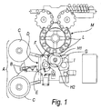
- Figures 1 and 2 of the accompanying drawings One common type of system currently in use for labeling bottles for beverages and the like is shown schematically in Figures 1 and 2 of the accompanying drawings, and comprises a unit A for feeding labels arranged in succession in a continuous ribbon B unwound from rolls C and fed by rollers D with a rotating blade E for cutting the ribbon B to size.
- Each label F is placed in contact with a transfer roller G, to which it adheres by way of a vacuum system (not shown in the figure), the endings of which are located at the rolling band of said transfer roller.
- each pad is constituted by a plate-like body made of plastic material, with mutually opposite raised rear edges for insertion in a suitable complementarily shaped undercut seat of the roller G, a front surface that is contoured so as to protrude from the rolling band of the roller G, and through holes that constitute the endings of the vacuum system.
- the pad is provided with a layer made of elastic material.
- Each label F that adheres to the feeder roller G is placed in contact with a paste distribution roller I, which has on its rolling surface a film of paste that is continuously restored and kept uniform.
- the paste distribution roller I has a knurled rolling surface, and the paste, by way of the presence of a doctor, is placed in the recesses of the knurling.
- the paste is distributed by spots or regions, depending on the type of knurling that is present on the surface of the paste distribution roller I.
- the transfer roller G brings, by rotating, the label F with the paste into contact with a corresponding bottle L of a rotating carousel M that is part of the bottling system.
- Each bottle L rolls about its own axis, and this movement, combined with the motion of the transfer roller G that is synchronized with it, transfers the label F onto the bottle L.
- the aim of the present invention is to eliminate the above-mentioned drawbacks of known types of container labeling system at least for regions having a cylindrical contour.
- an object of the invention is to further reduce the downtimes of the operation of the labeling system caused by malfunctions.
- Another object of the present invention is to provide modifications that can be provided and applied easily both in systems that are already in use and in newly manufactured systems.
- a pad for label transfer rollers in container labeling systems at least for regions having a cylindrical contour
- said pad being of the type that comprises a plate-like body with raised mutually opposite rear edges for insertion in a suitable complementarily shaped undercut seat of the roller, a front surface that is contoured so as to protrude from the rolling band of the roller, and through holes that constitute the endings of a vacuum system, said pad being characterized in that its front surface is at least partially knurled.
- the knurling is of the horizontally elongated parallel type.
- a first pad 10 for label transfer rollers 11 (which correspond to the rollers G of Figures 1 and 2) comprises a plate-like body 12 made of plastics, which has a rectangular contour with mutually opposite raised rear edges 13 for insertion in a suitable complementarily shaped undercut seat 14 of the roller 11.
- the body 12 is provided laterally with a semicylindrical recess 20 for a pin (not shown) for fixing to the roller 11.
- the pad 10 is provided with a layer 19 made of elastic material.
- the front surface 15 is contoured so as to protrude from the rolling band 16 of the roller and is provided with the outlets of through holes 17 that constitute the endings of a vacuum system, which is not shown for the sake of simplicity.
- the pad 10 in particular, has a front surface 15 that is composed of a portion 15a that is parallel to the line that is tangent to the roller 11 and is arranged between two inclined blending portions 15b.
- the front surface 15, in particular the portion 15a is at least partially knurled, with knurlings 18 of the horizontally elongated parallel type.
- each recess can be approximately 1 mm wide and approximately 0.5 mm deep.
- a pad 110 for label transfer rollers 11 comprises a plate-like body 112 made of plastics, which has a rectangular contour with mutually opposite raised rear edges 113 for insertion in a suitable complementarily shaped undercut seat 114 of the roller 11.
- the pad 110 has a layer 119 made of elastic material.
- the body 112 is provided laterally with a semicylindrical recess 120 for a pin (not shown) for fixing to the roller 11.
- the front surface 115 is contoured so as to protrude from the rolling band 16 of the roller and is provided with the outlets of through holes 117 that constitute the endings of a vacuum system, which is not shown for the sake of simplicity.
- the pad 110 in particular, has a front surface 115 that is composed of a portion 115a, which is parallel to the line that is tangent to the roller 11, and an inclined blending portion 115b.
- the front surface 115 is at least partially knurled, with knurlings 118 of the horizontally elongated parallel type.
- the fact that the front surface 15 and 115, which acts as a contrast surface (said contrast being elastic by way of the presence of the layers 19 and 119) for the paste distribution roller is knurled allows the actual contrast surface to be reduced, thus reducing the amount of paste transferred from the roller to the label and avoiding excess deposits that might cause problems.
- the materials used may be any according to requirements.
Landscapes
- Labeling Devices (AREA)
Abstract
Description
Claims (5)
- A pad for label transfer rollers in container labeling systems at least for regions having a cylindrical contour, said pad being of the type that comprises a plate-like body (12, 112) made of plastics with raised mutually opposite rear edges (13, 113) for insertion in a suitable complementarily shaped undercut seat (14, 114) of the roller (11), a front surface (15, 115) that is contoured so as to protrude from a rolling band (16) of the roller (11), and through holes (17, 117) that constitute the endings of a vacuum system, said pad being characterized in that its front surface (15, 115) is at least partially knurled.
- The pad according to claim 1, with a front surface (15) composed of a portion (15a) that is parallel to the line that is tangent to said roller (11) and is arranged between two inclined blending portions (15b), characterized in that said portion (15a) that is parallel to the tangent line is knurled.
- The pad according to claim 1, with a front surface composed of a portion (115a) that is parallel to the line that is tangent to said roller (11) and an inclined blending portion (115b), characterized in that said portion (115a) that is parallel to the line that is tangent to the roller is knurled.
- The pad according to one or more of the preceding claims, characterized in that knurling (18, 118) of the horizontally elongated parallel type is provided on said front surface (15,115).
- The pad according to one or more of the preceding claims, characterized in that said knurling (18, 118) has recesses that are each approximately 1 mm wide and approximately 0.5 mm deep.
Applications Claiming Priority (2)
| Application Number | Priority Date | Filing Date | Title |
|---|---|---|---|
| IT2002PD000057U ITPD20020057U1 (en) | 2002-07-30 | 2002-07-30 | IMPROVED SHOE FOR TRANSFER ROLLERS LABELS IN PLANTS LABELING OF CONTAINERS AT LEAST FOR CYLINDRICAL SHAPED AREAS |
| ITPD20020057 | 2002-07-30 |
Publications (2)
| Publication Number | Publication Date |
|---|---|
| EP1386843A1 true EP1386843A1 (en) | 2004-02-04 |
| EP1386843B1 EP1386843B1 (en) | 2006-03-22 |
Family
ID=30131407
Family Applications (1)
| Application Number | Title | Priority Date | Filing Date |
|---|---|---|---|
| EP03014466A Expired - Lifetime EP1386843B1 (en) | 2002-07-30 | 2003-07-01 | Pad for label transfer rollers in container labeling systems |
Country Status (4)
| Country | Link |
|---|---|
| EP (1) | EP1386843B1 (en) |
| AT (1) | ATE320972T1 (en) |
| DE (1) | DE60304081D1 (en) |
| IT (1) | ITPD20020057U1 (en) |
Cited By (4)
| Publication number | Priority date | Publication date | Assignee | Title |
|---|---|---|---|---|
| EP2109089A3 (en) * | 2008-04-12 | 2010-11-10 | Krones AG | Turnable label, device and method for attaching a turnable label |
| WO2022128857A1 (en) * | 2020-12-15 | 2022-06-23 | P.E. Labellers S.P.A. | Labeling machine |
| CN116917208A (en) * | 2021-02-23 | 2023-10-20 | Pe贴标机股份公司 | labeling machine |
| CN116761758B (en) * | 2020-12-15 | 2026-08-14 | Pe贴标机股份公司 | Labeling machine |
Citations (3)
| Publication number | Priority date | Publication date | Assignee | Title |
|---|---|---|---|---|
| US5111633A (en) * | 1989-12-18 | 1992-05-12 | G. D. Societa Per Azioni | Device for applying strips of material of packets of substantially parallelepiped shape |
| US5779835A (en) * | 1994-11-21 | 1998-07-14 | Cms Gilbreth Packaging Systems, Inc. | Method and apparatus for applying labels to articles using bottom feed chain conveyor |
| EP0872424A2 (en) * | 1997-03-18 | 1998-10-21 | Sasib Labelling Machinery S.p.A. | Labelling machine with cutting device working with label film in reel form |
-
2002
- 2002-07-30 IT IT2002PD000057U patent/ITPD20020057U1/en unknown
-
2003
- 2003-07-01 EP EP03014466A patent/EP1386843B1/en not_active Expired - Lifetime
- 2003-07-01 DE DE60304081T patent/DE60304081D1/en not_active Expired - Lifetime
- 2003-07-01 AT AT03014466T patent/ATE320972T1/en not_active IP Right Cessation
Patent Citations (3)
| Publication number | Priority date | Publication date | Assignee | Title |
|---|---|---|---|---|
| US5111633A (en) * | 1989-12-18 | 1992-05-12 | G. D. Societa Per Azioni | Device for applying strips of material of packets of substantially parallelepiped shape |
| US5779835A (en) * | 1994-11-21 | 1998-07-14 | Cms Gilbreth Packaging Systems, Inc. | Method and apparatus for applying labels to articles using bottom feed chain conveyor |
| EP0872424A2 (en) * | 1997-03-18 | 1998-10-21 | Sasib Labelling Machinery S.p.A. | Labelling machine with cutting device working with label film in reel form |
Cited By (6)
| Publication number | Priority date | Publication date | Assignee | Title |
|---|---|---|---|---|
| EP2109089A3 (en) * | 2008-04-12 | 2010-11-10 | Krones AG | Turnable label, device and method for attaching a turnable label |
| WO2022128857A1 (en) * | 2020-12-15 | 2022-06-23 | P.E. Labellers S.P.A. | Labeling machine |
| CN116761758A (en) * | 2020-12-15 | 2023-09-15 | Pe贴标机股份公司 | labeling machine |
| JP2023552617A (en) * | 2020-12-15 | 2023-12-18 | ピ・エ・ラベレルス・ソシエタ・ペル・アチオニ | label pasting device |
| CN116761758B (en) * | 2020-12-15 | 2026-08-14 | Pe贴标机股份公司 | Labeling machine |
| CN116917208A (en) * | 2021-02-23 | 2023-10-20 | Pe贴标机股份公司 | labeling machine |
Also Published As
| Publication number | Publication date |
|---|---|
| ATE320972T1 (en) | 2006-04-15 |
| DE60304081D1 (en) | 2006-05-11 |
| ITPD20020057U1 (en) | 2004-01-30 |
| EP1386843B1 (en) | 2006-03-22 |
Similar Documents
| Publication | Publication Date | Title |
|---|---|---|
| US4336095A (en) | Machine for labeling bodies and shoulders of containers | |
| US8402721B2 (en) | Beverage bottling or container filling plant having a beverage bottle or container labeling machine, and a beverage bottle or container labeling machine | |
| KR101926127B1 (en) | A labeling machine using a heterogeneous adhesive, and a PET bottle manufactured by the apparatus | |
| CA2113300A1 (en) | Apparatus and method for applying labels onto small cylindrical articles and web and adhesive delivery mechanism | |
| US4671843A (en) | Label transport vacuum drum | |
| CA1094941A (en) | Rotary die cutting assembly for cutting labels | |
| EP1386843B1 (en) | Pad for label transfer rollers in container labeling systems | |
| ES2048259T3 (en) | LABELING DEVICE FOR THE APPLICATION OF A LABEL TO AN OBJECT, MAINLY A LARGE LABEL ON A ROLL OF PAPER AND PROCEDURE FOR THE APPLICATION OF THE LABEL. | |
| CA2747929C (en) | Machine for labeling by means of labels printed on a ribbon | |
| EP0579026A1 (en) | Apparatus and method for applying labels onto small cylindrical articles using pressure applicator to prevent label mismatching | |
| EP1945515B1 (en) | Labelling articles | |
| US5458728A (en) | Apparatus and method for applying labels onto small cylindrical articles with improved seam formation by retarded article rotation | |
| CN205096185U (en) | Printing cleaning device | |
| EP0872424A3 (en) | Labelling machine with cutting device working with labelfilm in reel form | |
| JPS63296B2 (en) | ||
| CN1144733C (en) | Method and device for applying an imprint or label to an object | |
| CN210734733U (en) | Electronic product labeling machine | |
| US2635765A (en) | Labeling machine | |
| EP1179480B1 (en) | Labelling machine for non cylindrical containers | |
| EP0607341B1 (en) | A gluing palette and a glue-transfer part for use therewith | |
| KR102045516B1 (en) | Labeling device with heterogeneous adhesive supply means | |
| CA2747934C (en) | Machine for labeling by means of pre-pasted labels printed on a ribbon | |
| WO2000000397A3 (en) | Labelling apparatus and method | |
| US20100300581A1 (en) | Beverage bottle filling plant with a beverage bottle labeling machine, and a cutting arrangement for a beverage bottle labeling machine | |
| US3906896A (en) | Ink applicator |
Legal Events
| Date | Code | Title | Description |
|---|---|---|---|
| PUAI | Public reference made under article 153(3) epc to a published international application that has entered the european phase |
Free format text: ORIGINAL CODE: 0009012 |
|
| AK | Designated contracting states |
Kind code of ref document: A1 Designated state(s): AT BE BG CH CY CZ DE DK EE ES FI FR GB GR HU IE IT LI LU MC NL PT RO SE SI SK TR |
|
| AX | Request for extension of the european patent |
Extension state: AL LT LV MK |
|
| 17P | Request for examination filed |
Effective date: 20040706 |
|
| AKX | Designation fees paid |
Designated state(s): AT BE BG CH CY CZ DE DK EE ES FI FR GB GR HU IE IT LI LU MC NL PT RO SE SI SK TR |
|
| GRAP | Despatch of communication of intention to grant a patent |
Free format text: ORIGINAL CODE: EPIDOSNIGR1 |
|
| GRAS | Grant fee paid |
Free format text: ORIGINAL CODE: EPIDOSNIGR3 |
|
| GRAA | (expected) grant |
Free format text: ORIGINAL CODE: 0009210 |
|
| AK | Designated contracting states |
Kind code of ref document: B1 Designated state(s): AT BE BG CH CY CZ DE DK EE ES FI FR GB GR HU IE IT LI LU MC NL PT RO SE SI SK TR |
|
| PG25 | Lapsed in a contracting state [announced via postgrant information from national office to epo] |
Ref country code: AT Free format text: LAPSE BECAUSE OF FAILURE TO SUBMIT A TRANSLATION OF THE DESCRIPTION OR TO PAY THE FEE WITHIN THE PRESCRIBED TIME-LIMIT Effective date: 20060322 Ref country code: SK Free format text: LAPSE BECAUSE OF FAILURE TO SUBMIT A TRANSLATION OF THE DESCRIPTION OR TO PAY THE FEE WITHIN THE PRESCRIBED TIME-LIMIT Effective date: 20060322 Ref country code: LI Free format text: LAPSE BECAUSE OF FAILURE TO SUBMIT A TRANSLATION OF THE DESCRIPTION OR TO PAY THE FEE WITHIN THE PRESCRIBED TIME-LIMIT Effective date: 20060322 Ref country code: NL Free format text: LAPSE BECAUSE OF FAILURE TO SUBMIT A TRANSLATION OF THE DESCRIPTION OR TO PAY THE FEE WITHIN THE PRESCRIBED TIME-LIMIT Effective date: 20060322 Ref country code: CH Free format text: LAPSE BECAUSE OF FAILURE TO SUBMIT A TRANSLATION OF THE DESCRIPTION OR TO PAY THE FEE WITHIN THE PRESCRIBED TIME-LIMIT Effective date: 20060322 Ref country code: SI Free format text: LAPSE BECAUSE OF FAILURE TO SUBMIT A TRANSLATION OF THE DESCRIPTION OR TO PAY THE FEE WITHIN THE PRESCRIBED TIME-LIMIT Effective date: 20060322 Ref country code: RO Free format text: LAPSE BECAUSE OF FAILURE TO SUBMIT A TRANSLATION OF THE DESCRIPTION OR TO PAY THE FEE WITHIN THE PRESCRIBED TIME-LIMIT Effective date: 20060322 Ref country code: BE Free format text: LAPSE BECAUSE OF FAILURE TO SUBMIT A TRANSLATION OF THE DESCRIPTION OR TO PAY THE FEE WITHIN THE PRESCRIBED TIME-LIMIT Effective date: 20060322 |
|
| REG | Reference to a national code |
Ref country code: GB Ref legal event code: FG4D |
|
| REG | Reference to a national code |
Ref country code: CH Ref legal event code: EP |
|
| REG | Reference to a national code |
Ref country code: IE Ref legal event code: FG4D |
|
| REF | Corresponds to: |
Ref document number: 60304081 Country of ref document: DE Date of ref document: 20060511 Kind code of ref document: P |
|
| PG25 | Lapsed in a contracting state [announced via postgrant information from national office to epo] |
Ref country code: SE Free format text: LAPSE BECAUSE OF FAILURE TO SUBMIT A TRANSLATION OF THE DESCRIPTION OR TO PAY THE FEE WITHIN THE PRESCRIBED TIME-LIMIT Effective date: 20060622 Ref country code: BG Free format text: LAPSE BECAUSE OF FAILURE TO SUBMIT A TRANSLATION OF THE DESCRIPTION OR TO PAY THE FEE WITHIN THE PRESCRIBED TIME-LIMIT Effective date: 20060622 Ref country code: DK Free format text: LAPSE BECAUSE OF FAILURE TO SUBMIT A TRANSLATION OF THE DESCRIPTION OR TO PAY THE FEE WITHIN THE PRESCRIBED TIME-LIMIT Effective date: 20060622 |
|
| PG25 | Lapsed in a contracting state [announced via postgrant information from national office to epo] |
Ref country code: DE Free format text: LAPSE BECAUSE OF FAILURE TO SUBMIT A TRANSLATION OF THE DESCRIPTION OR TO PAY THE FEE WITHIN THE PRESCRIBED TIME-LIMIT Effective date: 20060623 |
|
| PG25 | Lapsed in a contracting state [announced via postgrant information from national office to epo] |
Ref country code: ES Free format text: LAPSE BECAUSE OF FAILURE TO SUBMIT A TRANSLATION OF THE DESCRIPTION OR TO PAY THE FEE WITHIN THE PRESCRIBED TIME-LIMIT Effective date: 20060703 Ref country code: IE Free format text: LAPSE BECAUSE OF NON-PAYMENT OF DUE FEES Effective date: 20060703 |
|
| PG25 | Lapsed in a contracting state [announced via postgrant information from national office to epo] |
Ref country code: MC Free format text: LAPSE BECAUSE OF NON-PAYMENT OF DUE FEES Effective date: 20060731 |
|
| PG25 | Lapsed in a contracting state [announced via postgrant information from national office to epo] |
Ref country code: PT Free format text: LAPSE BECAUSE OF FAILURE TO SUBMIT A TRANSLATION OF THE DESCRIPTION OR TO PAY THE FEE WITHIN THE PRESCRIBED TIME-LIMIT Effective date: 20060822 |
|
| NLV1 | Nl: lapsed or annulled due to failure to fulfill the requirements of art. 29p and 29m of the patents act | ||
| REG | Reference to a national code |
Ref country code: CH Ref legal event code: PL |
|
| PLBE | No opposition filed within time limit |
Free format text: ORIGINAL CODE: 0009261 |
|
| STAA | Information on the status of an ep patent application or granted ep patent |
Free format text: STATUS: NO OPPOSITION FILED WITHIN TIME LIMIT |
|
| 26N | No opposition filed |
Effective date: 20061227 |
|
| EN | Fr: translation not filed | ||
| GBPC | Gb: european patent ceased through non-payment of renewal fee |
Effective date: 20070701 |
|
| PG25 | Lapsed in a contracting state [announced via postgrant information from national office to epo] |
Ref country code: FR Free format text: LAPSE BECAUSE OF FAILURE TO SUBMIT A TRANSLATION OF THE DESCRIPTION OR TO PAY THE FEE WITHIN THE PRESCRIBED TIME-LIMIT Effective date: 20070309 Ref country code: GR Free format text: LAPSE BECAUSE OF FAILURE TO SUBMIT A TRANSLATION OF THE DESCRIPTION OR TO PAY THE FEE WITHIN THE PRESCRIBED TIME-LIMIT Effective date: 20060623 Ref country code: CZ Free format text: LAPSE BECAUSE OF FAILURE TO SUBMIT A TRANSLATION OF THE DESCRIPTION OR TO PAY THE FEE WITHIN THE PRESCRIBED TIME-LIMIT Effective date: 20060322 |
|
| PG25 | Lapsed in a contracting state [announced via postgrant information from national office to epo] |
Ref country code: GB Free format text: LAPSE BECAUSE OF NON-PAYMENT OF DUE FEES Effective date: 20070701 |
|
| PG25 | Lapsed in a contracting state [announced via postgrant information from national office to epo] |
Ref country code: FI Free format text: LAPSE BECAUSE OF FAILURE TO SUBMIT A TRANSLATION OF THE DESCRIPTION OR TO PAY THE FEE WITHIN THE PRESCRIBED TIME-LIMIT Effective date: 20060322 Ref country code: EE Free format text: LAPSE BECAUSE OF FAILURE TO SUBMIT A TRANSLATION OF THE DESCRIPTION OR TO PAY THE FEE WITHIN THE PRESCRIBED TIME-LIMIT Effective date: 20060322 |
|
| PG25 | Lapsed in a contracting state [announced via postgrant information from national office to epo] |
Ref country code: HU Free format text: LAPSE BECAUSE OF FAILURE TO SUBMIT A TRANSLATION OF THE DESCRIPTION OR TO PAY THE FEE WITHIN THE PRESCRIBED TIME-LIMIT Effective date: 20060923 Ref country code: TR Free format text: LAPSE BECAUSE OF FAILURE TO SUBMIT A TRANSLATION OF THE DESCRIPTION OR TO PAY THE FEE WITHIN THE PRESCRIBED TIME-LIMIT Effective date: 20060322 Ref country code: LU Free format text: LAPSE BECAUSE OF NON-PAYMENT OF DUE FEES Effective date: 20060701 |
|
| PG25 | Lapsed in a contracting state [announced via postgrant information from national office to epo] |
Ref country code: CY Free format text: LAPSE BECAUSE OF FAILURE TO SUBMIT A TRANSLATION OF THE DESCRIPTION OR TO PAY THE FEE WITHIN THE PRESCRIBED TIME-LIMIT Effective date: 20060322 Ref country code: FR Free format text: LAPSE BECAUSE OF FAILURE TO SUBMIT A TRANSLATION OF THE DESCRIPTION OR TO PAY THE FEE WITHIN THE PRESCRIBED TIME-LIMIT Effective date: 20060322 |
|
| PGFP | Annual fee paid to national office [announced via postgrant information from national office to epo] |
Ref country code: IT Payment date: 20160727 Year of fee payment: 14 |
|
| PG25 | Lapsed in a contracting state [announced via postgrant information from national office to epo] |
Ref country code: IT Free format text: LAPSE BECAUSE OF NON-PAYMENT OF DUE FEES Effective date: 20170701 |