EP1387130A1 - Fixierelement für Rohrabschnitte einer Erdwärmesonde - Google Patents
Fixierelement für Rohrabschnitte einer Erdwärmesonde Download PDFInfo
- Publication number
- EP1387130A1 EP1387130A1 EP02405668A EP02405668A EP1387130A1 EP 1387130 A1 EP1387130 A1 EP 1387130A1 EP 02405668 A EP02405668 A EP 02405668A EP 02405668 A EP02405668 A EP 02405668A EP 1387130 A1 EP1387130 A1 EP 1387130A1
- Authority
- EP
- European Patent Office
- Prior art keywords
- fixing element
- pipe
- pipe sections
- recesses
- geothermal probe
- Prior art date
- Legal status (The legal status is an assumption and is not a legal conclusion. Google has not performed a legal analysis and makes no representation as to the accuracy of the status listed.)
- Withdrawn
Links
- 239000000523 sample Substances 0.000 title claims abstract description 50
- 238000003780 insertion Methods 0.000 claims abstract description 23
- 230000037431 insertion Effects 0.000 claims abstract description 23
- 238000002347 injection Methods 0.000 claims description 3
- 239000007924 injection Substances 0.000 claims description 3
- 238000005304 joining Methods 0.000 abstract description 2
- 239000000725 suspension Substances 0.000 description 11
- SVPXDRXYRYOSEX-UHFFFAOYSA-N bentoquatam Chemical compound O.O=[Si]=O.O=[Al]O[Al]=O SVPXDRXYRYOSEX-UHFFFAOYSA-N 0.000 description 7
- 229910000278 bentonite Inorganic materials 0.000 description 6
- 239000000440 bentonite Substances 0.000 description 6
- 239000007788 liquid Substances 0.000 description 4
- 238000004519 manufacturing process Methods 0.000 description 4
- 238000001746 injection moulding Methods 0.000 description 3
- -1 polyethylene Polymers 0.000 description 3
- 239000000243 solution Substances 0.000 description 3
- XLYOFNOQVPJJNP-UHFFFAOYSA-N water Substances O XLYOFNOQVPJJNP-UHFFFAOYSA-N 0.000 description 3
- XEEYBQQBJWHFJM-UHFFFAOYSA-N Iron Chemical compound [Fe] XEEYBQQBJWHFJM-UHFFFAOYSA-N 0.000 description 2
- VYPSYNLAJGMNEJ-UHFFFAOYSA-N Silicium dioxide Chemical compound O=[Si]=O VYPSYNLAJGMNEJ-UHFFFAOYSA-N 0.000 description 2
- 239000004568 cement Substances 0.000 description 2
- 238000003754 machining Methods 0.000 description 2
- 239000002184 metal Substances 0.000 description 2
- 229910052751 metal Inorganic materials 0.000 description 2
- 229920000915 polyvinyl chloride Polymers 0.000 description 2
- 239000004800 polyvinyl chloride Substances 0.000 description 2
- 238000003466 welding Methods 0.000 description 2
- 229930040373 Paraformaldehyde Natural products 0.000 description 1
- 239000004952 Polyamide Substances 0.000 description 1
- 239000004698 Polyethylene Substances 0.000 description 1
- 239000004743 Polypropylene Substances 0.000 description 1
- 239000006004 Quartz sand Substances 0.000 description 1
- 229910000831 Steel Inorganic materials 0.000 description 1
- XECAHXYUAAWDEL-UHFFFAOYSA-N acrylonitrile butadiene styrene Chemical compound C=CC=C.C=CC#N.C=CC1=CC=CC=C1 XECAHXYUAAWDEL-UHFFFAOYSA-N 0.000 description 1
- 239000004676 acrylonitrile butadiene styrene Substances 0.000 description 1
- 229920000122 acrylonitrile butadiene styrene Polymers 0.000 description 1
- 239000007900 aqueous suspension Substances 0.000 description 1
- 230000009286 beneficial effect Effects 0.000 description 1
- 230000007797 corrosion Effects 0.000 description 1
- 238000005260 corrosion Methods 0.000 description 1
- 230000001419 dependent effect Effects 0.000 description 1
- 238000013461 design Methods 0.000 description 1
- 230000004927 fusion Effects 0.000 description 1
- 229910052742 iron Inorganic materials 0.000 description 1
- 239000000463 material Substances 0.000 description 1
- 150000002739 metals Chemical class 0.000 description 1
- 239000004033 plastic Substances 0.000 description 1
- 229920003023 plastic Polymers 0.000 description 1
- 229920002647 polyamide Polymers 0.000 description 1
- 229920000573 polyethylene Polymers 0.000 description 1
- 229920006324 polyoxymethylene Polymers 0.000 description 1
- 229920001155 polypropylene Polymers 0.000 description 1
- 238000003825 pressing Methods 0.000 description 1
- 239000004576 sand Substances 0.000 description 1
- 229910000679 solder Inorganic materials 0.000 description 1
- 238000005476 soldering Methods 0.000 description 1
- 239000010959 steel Substances 0.000 description 1
- 238000005728 strengthening Methods 0.000 description 1
- 229920001169 thermoplastic Polymers 0.000 description 1
- 239000004416 thermosoftening plastic Substances 0.000 description 1
- 238000012549 training Methods 0.000 description 1
- 238000012546 transfer Methods 0.000 description 1
Images


Classifications
-
- F—MECHANICAL ENGINEERING; LIGHTING; HEATING; WEAPONS; BLASTING
- F16—ENGINEERING ELEMENTS AND UNITS; GENERAL MEASURES FOR PRODUCING AND MAINTAINING EFFECTIVE FUNCTIONING OF MACHINES OR INSTALLATIONS; THERMAL INSULATION IN GENERAL
- F16L—PIPES; JOINTS OR FITTINGS FOR PIPES; SUPPORTS FOR PIPES, CABLES OR PROTECTIVE TUBING; MEANS FOR THERMAL INSULATION IN GENERAL
- F16L3/00—Supports for pipes, cables or protective tubing, e.g. hangers, holders, clamps, cleats, clips, brackets
- F16L3/22—Supports for pipes, cables or protective tubing, e.g. hangers, holders, clamps, cleats, clips, brackets specially adapted for supporting a number of parallel pipes at intervals
- F16L3/223—Supports for pipes, cables or protective tubing, e.g. hangers, holders, clamps, cleats, clips, brackets specially adapted for supporting a number of parallel pipes at intervals each support having one transverse base for supporting the pipes
-
- F—MECHANICAL ENGINEERING; LIGHTING; HEATING; WEAPONS; BLASTING
- F24—HEATING; RANGES; VENTILATING
- F24T—GEOTHERMAL COLLECTORS; GEOTHERMAL SYSTEMS
- F24T10/00—Geothermal collectors
- F24T10/10—Geothermal collectors with circulation of working fluids through underground channels, the working fluids not coming into direct contact with the ground
- F24T10/13—Geothermal collectors with circulation of working fluids through underground channels, the working fluids not coming into direct contact with the ground using tube assemblies suitable for insertion into boreholes in the ground, e.g. geothermal probes
- F24T10/15—Geothermal collectors with circulation of working fluids through underground channels, the working fluids not coming into direct contact with the ground using tube assemblies suitable for insertion into boreholes in the ground, e.g. geothermal probes using bent tubes; using tubes assembled with connectors or with return headers
-
- F—MECHANICAL ENGINEERING; LIGHTING; HEATING; WEAPONS; BLASTING
- F24—HEATING; RANGES; VENTILATING
- F24T—GEOTHERMAL COLLECTORS; GEOTHERMAL SYSTEMS
- F24T10/00—Geothermal collectors
- F24T2010/50—Component parts, details or accessories
- F24T2010/53—Methods for installation
-
- Y—GENERAL TAGGING OF NEW TECHNOLOGICAL DEVELOPMENTS; GENERAL TAGGING OF CROSS-SECTIONAL TECHNOLOGIES SPANNING OVER SEVERAL SECTIONS OF THE IPC; TECHNICAL SUBJECTS COVERED BY FORMER USPC CROSS-REFERENCE ART COLLECTIONS [XRACs] AND DIGESTS
- Y02—TECHNOLOGIES OR APPLICATIONS FOR MITIGATION OR ADAPTATION AGAINST CLIMATE CHANGE
- Y02E—REDUCTION OF GREENHOUSE GAS [GHG] EMISSIONS, RELATED TO ENERGY GENERATION, TRANSMISSION OR DISTRIBUTION
- Y02E10/00—Energy generation through renewable energy sources
- Y02E10/10—Geothermal energy
Definitions
- the invention relates to a fixing element for a pair of tubes a geothermal probe, especially for two pairs of pipes Geothermal probe.
- the invention also relates to a Fixing element, through the recesses pipe sections in axial direction are joined.
- a geothermal probe is used to exploit geothermal energy tubular heat exchanger inserted in the bottom.
- a Geothermal probes generally consist of one or two Pipe pairs.
- a liquid heat transfer medium is from one first probe head to a via a probe inlet pipe Probe foot guided, deflected there, and over a probe return pipe led to a second probe head.
- the both probe heads are connected via a collective inlet pipe or via a collective return pipe to a heat pump connected.
- the pipes Due to the curvature of the pipes, the pipes can only be with difficulty insert into the narrow borehole. In many cases Added to this is that the borehole is wholly or partially is filled with water or another liquid, so that due to the low specific weight of the empty pipes when immersed in the liquid get a boost that is strong insertion difficult.
- CH 653 120 A5 describes a device which inserting a geothermal probe into the borehole facilitated. Two pairs of pipes are connected by a clamp held together that the forward and return pipes of the Includes pairs of tubes. The distance between the front and Return pipes is made by a rod-shaped strut kept constant, attached in the center of the 4 pipes is. The rod-shaped strut is also with the Bride connected. The bracket and the rod-like strut are made of steel or iron and therefore susceptible to corrosion. A disadvantage of this device is that the bracket when Insert the geothermal probe into the borehole very easily slip, causing twisting and damage to the Pipe pairs can lead.
- the object of the present invention is a to create economic device with which one or several pairs of pipes without damage in a narrow borehole can be easily introduced.
- the fixing element according to the invention for pipe sections a geothermal probe has recesses for this are determined, pipe sections of a geothermal probe in axial direction.
- the geothermal probe has two with each other via a connector with a arcuate pipe part connected pipes.
- the through the Recesses to be joined pipe sections of the geothermal probe are preferably located in the immediate vicinity the connector with the arcuate tubular part, i.e. at the lower end of the drain pipe and at the beginning of the Return pipe.
- the pipe sections preferably have an attachment point. This can be, for example Weld seam between the pipe section and the Be connector with the arcuate tubular part.
- the fixing element according to the invention is dimensionally stable since it is integrally formed and the material is not is deformable. This ensures a constant distance the pipe sections guaranteed and a deflection after Outside or turning the pipes away is no longer possible.
- Anchor points is also a horizontal one Alignment of the fixing element guaranteed.
- the pipes are hit by the stops at a low point locked so that during insertion with pressure through an insertion rod from above, the inventive Fixing element is not moved in the axial direction.
- the fixing element according to the invention preferably has two or four recesses, which are intended Pipe sections from one or two pairs of pipes one Geothermal probe or two pairs of pipes of a geothermal probe in axial direction.
- the recesses extend over an arc segment an angle of 180 to 270 °. This will make them too joining pipe sections optimally held and attaching the pipe sections can be done very easily for example by inserting, pushing in, pressing in or clamping the pipe sections in the fixing element.
- the fixing element also has an abutting surface for the End portion of an insertion rod so that the Fixing element with the geothermal probe he holds be pushed into the borehole using an insertion rod can.
- the abutting surface is preferably in the center of the Fixing element attached. As long as the solder position during the insertion is not affected, but it is possible, the abutting surface against the edge of the fixing element to postpone.
- the butt surface can be on the Surface of the fixing element according to the invention.
- the butt surface is in a recess arranged to receive the end portion of the Insertion rod is determined. This gives the Insertion rod lateral hold, which makes insertion strong simplified, since slipping away is prevented.
- the fixing element according to the invention easier insertion of the geothermal probe into the Borehole, the soldering of the geothermal probe during the insertion is ensured and thus protection the same is guaranteed against damage.
- the fixing element according to the invention can also Flow channels included, which are intended that after the introduction of suspensions and solutions such as Example a bentonite / sand / water suspension Fixing element can still easily happen.
- suitable Suspensions are Stüwamix® and Stüwatherm® from the company Stüwa or Tixoton® from Südchemie.
- Side wall of the fixing element according to the invention preferably shifted inwards, i.e. it suits Center of the fixing element closer than the farthest after outside surface line of the axially in the recesses joined pipe sections. So that the fixing element comes when inserting into the borehole, on the one hand, not with the Wall in contact, which minimizes friction and on the other hand, there are further openings through which Suspension and liquids pass through the fixing element can.
- the fixing element can also be a device for Have attachment of an injection tube. This can for example another recess or a tab his.
- a suspension such as a suspension of bentonite, cement and Water to be placed in the borehole. More suitable Suspensions and solutions used for this can are known to the expert. These suspensions and Solutions stabilize both the borehole and the Geothermal probe in the borehole.
- bentonite is for coarse-grained sands and gravel to stabilize the Borehole important.
- the Fixing element according to the invention is constructional easy to manufacture.
- the production can for example by machining or by a Injection molding process.
- mechanical strengthening of the fixing element are polyethylene and Polyvinyl chloride.
- Injection molding processes are suitable for acrylonitrile-butadiene-styrene copolymers, Polypropylene, polyoxymethylene, Polyamides and polyvinyl chloride are particularly good.
- Fig. 1 shows a fixing element 1, which thermoplastic or metal is made.
- the fixing element 1 has four recesses 13, 14, 15, 16 on, which are designed to pipe sections of two Pipe pairs of a geothermal probe axially.
- the Recesses 13, 14, 15, 16 can be machined Machining can be made, but it is also possible Fixing element 1 by means of an injection molding process manufacture.
- the fixing element 1 is symmetrical formed, the distances between adjacent Recesses 13, 14, 15, 16 are each the same. A However, symmetrical training is not mandatory.
- the Recesses 13, 14, 15, 16 are circular and extend over an arc segment of 180 °. However, it would be too possible to design the recesses 13, 14, 15, 16 in such a way that they are over an arc segment of up to 270 ° extend.
- the recesses 13, 14, 15, 16 adjacent edges 18 of the fixing element 1 beveled, but it would also be possible to round it off.
- an abutting surface 20 arranged to receive the end portion of a Insertion rod is determined.
- the push surface for the insertion rod can, however, also from the flat surface 22 of the Fixing element 1 may be formed.
- the face is in the The embodiment shown here is smooth, however Rough, ribbed or grooved butt surfaces are also conceivable.
- FIG. 2 shows a further embodiment of the one in FIG. 1 shown fixing element 1 '.
- the fixing element 1 ' additionally has flow channels 28 which Fixing element 1 'vertically from top to bottom penetrate. Through it, after inserting the Geothermal probe a good heat conductive suspension, such as Example, a suspension of water and bentonite, passed which later solidifies and the geothermal probe more Holds and stabilizes the borehole.
- a good heat conductive suspension such as Example
- FIG. 3 shows the fixing element 1 shown in FIG. 1 thereof four recesses 13, 14, 15, 16 tube sections 23, 24, 25, 26 join axially.
- Two pipe sections 23, 24 and 25, 26 each are with each other via a connector 38 connected.
- the connector is essentially Y-shaped formed and has three pipe sections 30,31,32 on, of which a pipe section 31 the Y trunk part forms.
- the other two belonging to the connector Pipe sections 30, 32 are each arcuate Pipe part 35.36 with that forming the Y trunk part Pipe section 31 connected and form together with the the latter the legs of the Y-shaped connector.
- the plug 40 protects with its bottom part 42 Geothermal probe also before damage during of insertion into the borehole.
- the tab 44 of the stopper 40 acts as an insertion of the geothermal probe into the Borehole relieving impact element. Bores 46.47 in the tab 44 allow a weight to be attached at the lowest point of the geothermal probe, which is the buoyancy counteracts.
- the connector 38 is with the Pipe sections 23.24 and 25.26 on the to Connector belonging pipe sections 30,32 connected. The connection is preferably by means of Electrofusion welding or butt fusion welding manufactured.
- the weld seam on the pipe sections 23, 24, 25, 26 serves as an attachment point 50 Stopping points 50 of the four pipe sections 23, 24, 25, 26 prevent the fixing element 1 further in the direction Connector 38 can be pushed.
- the fixing element 1 rests on the stop point 50 lateral twisting of the pipes is no longer possible, which has the consequence that the fixing element 1 the Pipe sections 23,24,25,26, and thus both pairs of pipes Geothermal probe, stabilized equidistantly.
- the Fixing element according to the invention thus enables simple insertion of the geothermal probe into boreholes can also have a depth of over 50 meters without that the geothermal probe in serpentine form on the Walls of the borehole.
- the Fixing element 1 according to the invention becomes the geothermal probe inserted safely and without damage into the borehole. This also has the advantage of resistance is reduced due to friction.
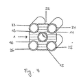
- FIG. 4 shows the fixing element 1 shown in FIG. 1 the recesses 13, 14, 15, 16, which are the pipe sections 23,24,25,26 join axially.
- the fixing element 1 when inserted into the borehole inevitably not in contact with the wall of the borehole.
- a Bentonite suspension bentonite cement quartz sand or others suspensions known to those skilled in the art
- the fixing element 1 described in FIG. 1 with the recesses 13,14,15,16 shown, the Pipe sections 23, 24, 25, 26 of two pairs of pipes one Inserts geothermal probe axially. As can be seen from this, are the pairs of tubes are arranged offset to one another.
- the Welded connection forms the stop point 50 for the Fixing element 1.
- the fixing element 1 lies exclusively on the stop points 50 of two pipe sections, i.e. from a pair of tubes of the geothermal probe. Because of the close However, the two pairs of pipes lie against each other ensures that through the cooperation of the Stop point 50 and base of the fixing element 1 one side, the pipe sections 23,24,25,26 equidistant are stabilized and the fixing element 1 is not can slip.
- a weight 54 is attached to the buoyancy counteracts and the insertion of the geothermal probe strongly facilitated.
- the weights are preferably 10 to 40 kg heavy, weights from 12.5 to Weigh 25 kg.
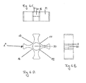
- FIG. 6A shows a further embodiment of a fixing element 1 II , in which the recesses 13, 14, 15, 16 are designed for pipe sections 23, 24, 25, 26 with a diameter of 40 cm.
- the distances to adjacent recesses are different, but an identical arrangement would also be possible. Fixing elements with other diameters are also conceivable.
- Fig. 7 shows the embodiment shown in Fig. 3, in which in the holes 46,47 in the tab 44 of the Geothermal probe a weight 54 is attached, which the Counteracts buoyancy and the insertion of the geothermal probe greatly relieved.
- the plug could instead of two, just one hole to attach the Have weight, or by other means for Attaching the weight equipped or otherwise weighted down his.
Landscapes
- Engineering & Computer Science (AREA)
- General Engineering & Computer Science (AREA)
- Life Sciences & Earth Sciences (AREA)
- Mechanical Engineering (AREA)
- General Life Sciences & Earth Sciences (AREA)
- Sustainable Development (AREA)
- Sustainable Energy (AREA)
- Chemical & Material Sciences (AREA)
- Combustion & Propulsion (AREA)
- Geophysics And Detection Of Objects (AREA)
Abstract
Description
- Fig. 1a
- ein ersten Ausführungsbeispiel eines Fixierelements in Draufsicht;
- Fig. 1b/c
- das in Fig. 1a gezeigte Fixierelement in Seitenansicht;
- Fig. 2a
- ein weiteres Ausführungsbeispiel eines Fixierelements mit Durchflusskanälen in Draufsicht;
- Fig. 2b/c
- das in Fig. 2a gezeigte Fixierelement in Seitenansicht;
- Fig. 3
- das in Fig. 1 gezeigte Fixierelement, das die Rohrabschnitte von zwei Rohrpaaren einer Erdwärmesonde fügt;
- Fig. 4
- einen Schnitt nach Linie A-A nach Fig. 3;
- Fig. 5
- das in Fig. 1 gezeigte Fixierelement, das die Rohrabschnitte von zwei Rohrpaaren einer Erdwärmesonde mit einem Gewicht fügt;
- Fig. 6a
- ein weiteres Ausführungsbeispiel eines Fixierelements in Draufsicht;
- Fig. 6b/c
- das in Fig. 6a gezeigte Fixierelement in Seitenansicht;
- Fig. 7
- die in Fig. 3 gezeigte Erdwärmesonde mit einem Gewicht;
Claims (11)
- Fixierelement (1) für Rohrabschnitte (23,24) eines Rohrpaares einer Erdwärmesonde, die über ein Verbindungsstück (38) mit einem bogenförmigen Rohrteil miteinander verbundene Rohre aufweist, dadurch gekennzeichnet, dass das Fixierelement (1) zwei Ausnehmungen (13,14) besitzt, deren Radien den Aussenradien der Rohrabschnitte (23, 24) entsprechen und die Ausnehmungen (13,14) Rohrabschnitte (23,24) in axialer Richtung zu fügen bestimmt sind, wobei das Fixierelement (1) als Stossauflage (20) eine Stossfläche für eine Einführstange für die Erdwärmesonde aufweist.
- Fixierelement (1) gemäss Anspruch 1, dadurch gekennzeichnet, dass das Fixierelement (1) dazu bestimmt ist, mit einer Anschlagsstelle (50) der beiden Rohrabschnitte (23,24) zusammenzuwirken.
- Fixierelement (1) gemäss einem der vorangehenden Ansprüche, dadurch gekennzeichnet, dass das Fixierelement zwei weitere Ausnehmungen (15,16) aufweist, die dazu bestimmt sind, zwei Rohrabschnitte (25,26) eines weiteren Rohrpaares, das über ein bogenförmiges Rohrteil miteinander verbundene Rohre aufweist, in axialer Richtung zu fügen.
- Fixierelement (1) gemäss einem der vorangehenden Ansprüche, dadurch gekennzeichnet, dass die Ausnehmung (13,14,15,16) sich über ein Bogensegment mit einem Öffnungswinkel von 180 bis 270° erstreckt.
- Fixierelement (1) gemäss einem der vorangehenden Ansprüche, dadurch gekennzeichnet, dass die Stossfläche (20) für die Einführstange in einer Ausnehmung angeordnet ist, die zur Aufnahme des Endabschnittes der Einführstange bestimmt ist.
- Fixierelement (1) gemäss einem der vorangehenden Ansprüche, dadurch gekennzeichnet, dass das Fixierelement (1) Durchflusskanäle (28) aufweist.
- Fixierelement (1) gemäss einem der vorangehenden Ansprüche, dadurch gekennzeichnet, dass das Fixierelement (1) eine Vorrichtung zur Befestigung eines Injektionsrohres aufweist.
- Fixierelement (1) gemäss einem der vorangehenden Ansprüche mit einem Rohrpaar einer Erdwärmesonde, in dem Rohrabschnitte (23,24) durch die Ausnehmungen (13,14) in axialer Richtung gefügt sind.
- Fixierelement (1) gemäss einem der Ansprüche 3 bis 8 mit zwei Rohrpaaren einer Erdwärmesonde, in dem Rohrabschnitte (23,24,25,26) von zwei Rohrpaaren einer Erdwärmesonde durch die Ausnehmungen (13,14,15,16) in axialer Richtung gefügt sind, dadurch gekennzeichnet, dass die Anschlagsstellen (50) sämtlicher Rohrabschnitte (23,24,25,26) mit dem Fixierelement (1) zusammenwirken.
- Fixierelement (1) gemäss einem der Ansprüche 3 bis 8 mit zwei Rohrpaaren einer Erdwärmesonde, in dem Rohrabschnitte (23,24,25,26) von zwei Rohrpaare durch die Ausnehmungen (13,14,15,16) in axialer Richtung gefügt sind, dadurch gekennzeichnet, dass die Anschlagsstellen (50) von nur zwei Rohrabschnitten (23,24), die über ein bogenförmiges Rohrteil miteinander verbunden sind, mit dem Fixierelement (1) zusammenwirken.
- Fixierelement (1) mit Ausnehmungen (13,14,15,16) gemäss einem der vorangehenden Ansprüche, die Rohrabschnitte (23,24,25,26) von Rohrpaaren einer Erdwärmesonde in axialer Richtung fügen, wobei das Rohrpaar über ein Verbindungsstück (38) mit einem bogenförmigen Rohrteil miteinander verbundene Rohre aufweist und das Verbindungsstück (38) im wesentlichen eine Y-Form aufweist, dadurch gekennzeichnet, dass das Verbindungsstück (38) drei parallelen verlaufende Rohrabschnitte (30,31,32) aufweist, von denen der eine Rohrabschnitt (31) den Y-Stammteil bildet, mit dem die beiden anderen (30,32), über einen bogenförmigen Rohrteil (35,36) miteinander verbunden sind.
Priority Applications (1)
| Application Number | Priority Date | Filing Date | Title |
|---|---|---|---|
| EP02405668A EP1387130A1 (de) | 2002-07-31 | 2002-07-31 | Fixierelement für Rohrabschnitte einer Erdwärmesonde |
Applications Claiming Priority (1)
| Application Number | Priority Date | Filing Date | Title |
|---|---|---|---|
| EP02405668A EP1387130A1 (de) | 2002-07-31 | 2002-07-31 | Fixierelement für Rohrabschnitte einer Erdwärmesonde |
Publications (1)
| Publication Number | Publication Date |
|---|---|
| EP1387130A1 true EP1387130A1 (de) | 2004-02-04 |
Family
ID=30011306
Family Applications (1)
| Application Number | Title | Priority Date | Filing Date |
|---|---|---|---|
| EP02405668A Withdrawn EP1387130A1 (de) | 2002-07-31 | 2002-07-31 | Fixierelement für Rohrabschnitte einer Erdwärmesonde |
Country Status (1)
| Country | Link |
|---|---|
| EP (1) | EP1387130A1 (de) |
Cited By (14)
| Publication number | Priority date | Publication date | Assignee | Title |
|---|---|---|---|---|
| DE102006011161A1 (de) * | 2006-03-10 | 2007-09-13 | Joachim Pinkl | Stabiler Sondenfuß für eine Erdsonde |
| DE102007017078B3 (de) * | 2007-04-10 | 2008-11-27 | Pumpenboese Gmbh & Co. Kg | Erdwärmesonde und Zentrierelement für Erdwärmesonden |
| DE102007024656A1 (de) * | 2007-05-26 | 2008-11-27 | Joachim Pinkl | Sondenfuß Gemini für eine Erdsonde |
| EP2034254A2 (de) | 2007-09-06 | 2009-03-11 | Erwin Kopp | Vorrichtung zum Schutz eines Sondenfusses für eine Erdsonde |
| EP2123995A1 (de) | 2008-05-23 | 2009-11-25 | HAKA.Gerodur AG | Einführvorrichtung für eine Erdwärmesonde |
| WO2009129778A3 (de) * | 2008-04-22 | 2010-03-25 | Friatec Aktiengesellschaft | Modular aufgebauter sondenfuss und seine komponenten |
| DE202009011508U1 (de) | 2009-08-27 | 2011-01-05 | Rehau Ag + Co. | Sondenfuß für eine Erdwärmesonde und Erdwärmesonde, die den Sondenfuß umfasst |
| JP2011149663A (ja) * | 2010-01-25 | 2011-08-04 | Misawa Kankyo Gijutsu Kk | U字管挿入装置および挿入方法 |
| EP2395301A1 (de) * | 2010-06-14 | 2011-12-14 | HAKA.Gerodur AG | Verbindungsstück für Rohrleitungen einer Erdwärmesondenanlage |
| WO2012159761A1 (fr) | 2011-05-25 | 2012-11-29 | S.A. Ryb | Pied de sonde geothermique et procede de mise en place |
| JP2013213522A (ja) * | 2012-03-30 | 2013-10-17 | Sekisui Chem Co Ltd | 配管継手及びこれを用いた配管システム |
| JP2014070697A (ja) * | 2012-09-28 | 2014-04-21 | Sekisui Chem Co Ltd | チューブ保持スペーサ |
| EP4137753A4 (de) * | 2019-06-26 | 2024-05-15 | G&G Technology Co., Ltd. | Geothermisches system mit vertikal versiegeltem unterirdischem mehrrohrwärmetauscher und installationsverfahren dafür |
| US12241659B2 (en) | 2020-03-13 | 2025-03-04 | Robert Jensen | Twisted conduit for geothermal heat exchange |
Citations (6)
| Publication number | Priority date | Publication date | Assignee | Title |
|---|---|---|---|---|
| US3437297A (en) * | 1965-09-14 | 1969-04-08 | Anger Kunststoff | Support members for pipes |
| CH653120A5 (en) | 1984-03-30 | 1985-12-13 | Grundag Ag Gossau | Earth probe for introduction into a vertical borehole |
| DE8808676U1 (de) * | 1987-09-07 | 1988-09-29 | Grundag AG Gossau, Gossau | Vorrichtung zum Einführen einer Erdsonde |
| DE9403070U1 (de) * | 1993-04-21 | 1994-07-07 | Grundag AG, Gossau | Vorrichtung zum Einführen einer Erdsonde in ein Bohrloch |
| WO1999063282A1 (en) * | 1998-06-01 | 1999-12-09 | Enlink Geoenergy Services, Inc. | Earth heat exchange system |
| EP1036974A1 (de) * | 1999-03-16 | 2000-09-20 | HAKA.Gerodur AG | Verbindungsstück aus thermoplastischem Kunststoff für Rohrleitungen einer Erdsondenanlage |
-
2002
- 2002-07-31 EP EP02405668A patent/EP1387130A1/de not_active Withdrawn
Patent Citations (6)
| Publication number | Priority date | Publication date | Assignee | Title |
|---|---|---|---|---|
| US3437297A (en) * | 1965-09-14 | 1969-04-08 | Anger Kunststoff | Support members for pipes |
| CH653120A5 (en) | 1984-03-30 | 1985-12-13 | Grundag Ag Gossau | Earth probe for introduction into a vertical borehole |
| DE8808676U1 (de) * | 1987-09-07 | 1988-09-29 | Grundag AG Gossau, Gossau | Vorrichtung zum Einführen einer Erdsonde |
| DE9403070U1 (de) * | 1993-04-21 | 1994-07-07 | Grundag AG, Gossau | Vorrichtung zum Einführen einer Erdsonde in ein Bohrloch |
| WO1999063282A1 (en) * | 1998-06-01 | 1999-12-09 | Enlink Geoenergy Services, Inc. | Earth heat exchange system |
| EP1036974A1 (de) * | 1999-03-16 | 2000-09-20 | HAKA.Gerodur AG | Verbindungsstück aus thermoplastischem Kunststoff für Rohrleitungen einer Erdsondenanlage |
Cited By (19)
| Publication number | Priority date | Publication date | Assignee | Title |
|---|---|---|---|---|
| DE102006011161A1 (de) * | 2006-03-10 | 2007-09-13 | Joachim Pinkl | Stabiler Sondenfuß für eine Erdsonde |
| DE102007017078B3 (de) * | 2007-04-10 | 2008-11-27 | Pumpenboese Gmbh & Co. Kg | Erdwärmesonde und Zentrierelement für Erdwärmesonden |
| DE102007024656A1 (de) * | 2007-05-26 | 2008-11-27 | Joachim Pinkl | Sondenfuß Gemini für eine Erdsonde |
| EP2034254A2 (de) | 2007-09-06 | 2009-03-11 | Erwin Kopp | Vorrichtung zum Schutz eines Sondenfusses für eine Erdsonde |
| AT505668B1 (de) * | 2007-09-06 | 2009-03-15 | Erwin F Kopp | Vorrichtung zum schutz eines sondenfusses für eine erdsonde |
| WO2009129778A3 (de) * | 2008-04-22 | 2010-03-25 | Friatec Aktiengesellschaft | Modular aufgebauter sondenfuss und seine komponenten |
| EP2123995A1 (de) | 2008-05-23 | 2009-11-25 | HAKA.Gerodur AG | Einführvorrichtung für eine Erdwärmesonde |
| EP2123994A1 (de) | 2008-05-23 | 2009-11-25 | HAKA.Gerodur AG | Einführvorrichtung für eine Erdwärmesonde |
| DE202009011508U1 (de) | 2009-08-27 | 2011-01-05 | Rehau Ag + Co. | Sondenfuß für eine Erdwärmesonde und Erdwärmesonde, die den Sondenfuß umfasst |
| WO2011023310A2 (de) | 2009-08-27 | 2011-03-03 | Rehau Ag + Co | Sondenfuss für eine erdwärmesonde und erdwärmesonde, die den sondenfuss umfasst |
| WO2011023310A3 (de) * | 2009-08-27 | 2012-07-19 | Rehau Ag + Co | Sondenfuss für eine erdwärmesonde und erdwärmesonde, die den sondenfuss umfasst |
| JP2011149663A (ja) * | 2010-01-25 | 2011-08-04 | Misawa Kankyo Gijutsu Kk | U字管挿入装置および挿入方法 |
| EP2395301A1 (de) * | 2010-06-14 | 2011-12-14 | HAKA.Gerodur AG | Verbindungsstück für Rohrleitungen einer Erdwärmesondenanlage |
| WO2012159761A1 (fr) | 2011-05-25 | 2012-11-29 | S.A. Ryb | Pied de sonde geothermique et procede de mise en place |
| JP2013213522A (ja) * | 2012-03-30 | 2013-10-17 | Sekisui Chem Co Ltd | 配管継手及びこれを用いた配管システム |
| JP2014070697A (ja) * | 2012-09-28 | 2014-04-21 | Sekisui Chem Co Ltd | チューブ保持スペーサ |
| EP4137753A4 (de) * | 2019-06-26 | 2024-05-15 | G&G Technology Co., Ltd. | Geothermisches system mit vertikal versiegeltem unterirdischem mehrrohrwärmetauscher und installationsverfahren dafür |
| US12025350B2 (en) | 2019-06-26 | 2024-07-02 | G&G Technology Co., Ltd. | Geothermal system comprising multitube vertically-sealed underground heat-exchanger and method for installing same |
| US12241659B2 (en) | 2020-03-13 | 2025-03-04 | Robert Jensen | Twisted conduit for geothermal heat exchange |
Similar Documents
| Publication | Publication Date | Title |
|---|---|---|
| EP1387130A1 (de) | Fixierelement für Rohrabschnitte einer Erdwärmesonde | |
| DE2306969A1 (de) | Klemmvorrichtung zur befestigung langgestreckter koerper | |
| DE10259138A1 (de) | Verbindungsstruktur einer Abzweigleitung in einem Kraftstoff-Druck-Sammelbehälter | |
| EP1036974B1 (de) | Verbindungsstück aus thermoplastischem Kunststoff für Rohrleitungen einer Erdsondenanlage | |
| EP2913607B1 (de) | Erdwärmesondenfuß und Erdwärmesonde | |
| CH687268A5 (de) | Sondenfuss fuer eine Erdsonde. | |
| WO2020148065A1 (de) | Tragstruktur für eine windkraftanlage | |
| EP2395301B1 (de) | Verbindungsstück für Rohrleitungen einer Erdwärmesondenanlage | |
| WO2009129778A2 (de) | Modular aufgebauter sondenfuss und seine komponenten | |
| DE1477730A1 (de) | Bohrer | |
| DE20021105U1 (de) | Sondenfuß | |
| DE2011440A1 (de) | ||
| DE1939955A1 (de) | Verfahren zum Herstellen von Rohren oder aehnlichen Gegenstaenden und Rohr od.dgl. | |
| DE29803944U1 (de) | Meißelsicherung für einen Hobelmeißel | |
| DE69512820T2 (de) | Bodenverankerungspfahl | |
| AT510325B1 (de) | Sondenkopf | |
| DE102007017078B3 (de) | Erdwärmesonde und Zentrierelement für Erdwärmesonden | |
| DE20120098U1 (de) | Bauteilverbindung bei Fahrwerkskomponenten | |
| DE69510770T2 (de) | Rohrverbindung und Verfahren zur seiner Herstellung | |
| DE8425270U1 (de) | Vorrichtung zum Befestigen von Wärmekörpern | |
| DE2940030C2 (de) | Knotenpunkt für lösbare biegesteife Eckverbindungen von Stäben | |
| DE10228479B4 (de) | Stütze für den Baubereich | |
| DE19835948C1 (de) | Fahrbahnbegrenzung für Kraftfahrzeuge | |
| DE10255067B4 (de) | Gassackanordnung mit starrer Gaslanze | |
| DE202018003826U1 (de) | Bohrhilfe |
Legal Events
| Date | Code | Title | Description |
|---|---|---|---|
| PUAI | Public reference made under article 153(3) epc to a published international application that has entered the european phase |
Free format text: ORIGINAL CODE: 0009012 |
|
| AK | Designated contracting states |
Kind code of ref document: A1 Designated state(s): AT BE BG CH CY CZ DE DK EE ES FI FR GB GR IE IT LI LU MC NL PT SE SK TR |
|
| AX | Request for extension of the european patent |
Extension state: AL LT LV MK RO SI |
|
| 17P | Request for examination filed |
Effective date: 20040726 |
|
| AKX | Designation fees paid |
Designated state(s): AT BE BG CH CY CZ DE DK EE ES FI FR GB GR IE IT LI LU MC NL PT SE SK TR |
|
| 17Q | First examination report despatched |
Effective date: 20041005 |
|
| STAA | Information on the status of an ep patent application or granted ep patent |
Free format text: STATUS: THE APPLICATION IS DEEMED TO BE WITHDRAWN |
|
| 18D | Application deemed to be withdrawn |
Effective date: 20050418 |